2006 SUZUKI SWIFT IGN
[x] Cancel search: IGNPage 1307 of 1496
Downloaded from www.Manualslib.com manuals search engine Instrumentation / Driver Info. / Horn: 9C-12
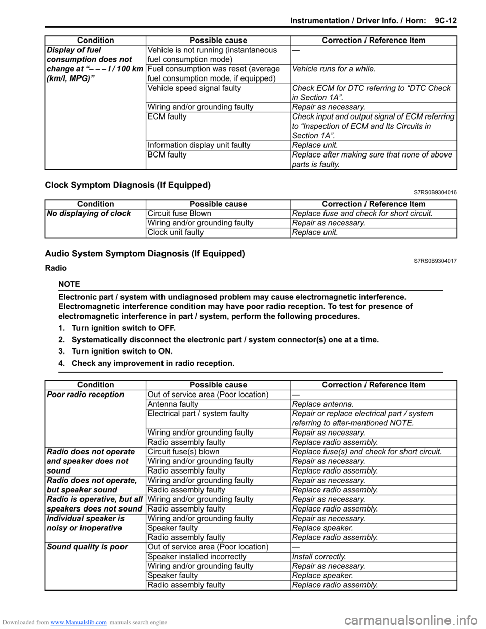
Clock Symptom Diagnosis (If Equipped)S7RS0B9304016
Audio System Symptom Diagnosis (If Equipped)S7RS0B9304017
Radio
NOTE
Electronic part / system with undiagnosed pr oblem may cause electromagnetic interference.
Electromagnetic interference condition may have poor radio reception. To test for presence of
electromagnetic interference in part / system, perform the following procedures.
1. Turn ignition switch to OFF.
2. Systematically disconnect the electronic part / system connector(s) one at a time.
3. Turn ignition switch to ON.
4. Check any improvement in radio reception.
Display of fuel
consumption does not
change at “– – – l / 100 km
(km/l, MPG)” Vehicle is not running (instantaneous
fuel consumption mode)
—
Fuel consumption was reset (average
fuel consumption mo de, if equipped)Vehicle runs for a while.
Vehicle speed signal faulty Check ECM for DTC referring to “DTC Check
in Section 1A”.
Wiring and/or grounding faulty Repair as necessary.
ECM faulty Check input and output signal of ECM referring
to “Inspection of ECM and Its Circuits in
Section 1A”.
Information display unit faulty Replace unit.
BCM faulty Replace after making sure that none of above
parts is faulty.
Condition Possible cause Correction / Reference Item
Condition
Possible cause Correction / Reference Item
No displaying of clock Circuit fuse Blown Replace fuse and check for short circuit.
Wiring and/or grounding faulty Repair as necessary.
Clock unit faulty Replace unit.
ConditionPossible cause Correction / Reference Item
Poor radio reception Out of service area (Poor location) —
Antenna faulty Replace antenna.
Electrical part / system faulty Repair or replace electrical part / system
referring to after-mentioned NOTE.
Wiring and/or grounding faulty Repair as necessary.
Radio assembly faulty Replace radio assembly.
Radio does not operate
and speaker does not
sound Circuit fuse(s) blown
Replace fuse(s) and check for short circuit.
Wiring and/or grounding faulty Repair as necessary.
Radio assembly faulty Replace radio assembly.
Radio does not operate,
but speaker sound Wiring and/or grounding faulty
Repair as necessary.
Radio assembly faulty Replace radio assembly.
Radio is operative, but all
speakers does not sound Wiring and/or grounding faulty
Repair as necessary.
Radio assembly faulty Replace radio assembly.
Individual speaker is
noisy or inoperative Wiring and/or grounding faulty
Repair as necessary.
Speaker faulty Replace speaker.
Radio assembly faulty Replace radio assembly.
Sound quality is poor Out of service area (Poor location) —
Speaker installed incorrectly Install correctly.
Wiring and/or grounding faulty Repair as necessary.
Speaker faulty Replace speaker.
Radio assembly faulty Replace radio assembly.
Page 1308 of 1496
Downloaded from www.Manualslib.com manuals search engine 9C-13 Instrumentation / Driver Info. / Horn:
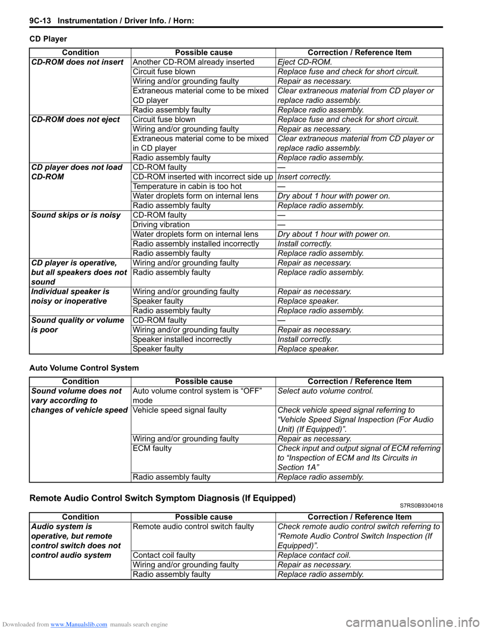
CD Player
Auto Volume Control System
Remote Audio Control Switch Symptom Diagnosis (If Equipped)S7RS0B9304018
ConditionPossible cause Correction / Reference Item
CD-ROM does not insert Another CD-ROM already inserted Eject CD-ROM.
Circuit fuse blown Replace fuse and check for short circuit.
Wiring and/or grounding faulty Repair as necessary.
Extraneous material come to be mixed
CD player Clear extraneous material from CD player or
replace radio assembly.
Radio assembly faulty Replace radio assembly.
CD-ROM does not eject Circuit fuse blown Replace fuse and check for short circuit.
Wiring and/or grounding faulty Repair as necessary.
Extraneous material come to be mixed
in CD player Clear extraneous material from CD player or
replace radio assembly.
Radio assembly faulty Replace radio assembly.
CD player does not load
CD-ROM CD-ROM faulty
—
CD-ROM inserted wit h incorrect side upInsert correctly.
Temperature in cabin is too hot —
Water droplets form on internal lens Dry about 1 hour with power on.
Radio assembly faulty Replace radio assembly.
Sound skips or is noisy CD-ROM faulty —
Driving vibration —
Water droplets form on internal lens Dry about 1 hour with power on.
Radio assembly installed incorrectly Install correctly.
Radio assembly faulty Replace radio assembly.
CD player is operative,
but all speakers does not
sound Wiring and/or grounding faulty
Repair as necessary.
Radio assembly faulty Replace radio assembly.
Individual speaker is
noisy or inoperative Wiring and/or grounding faulty
Repair as necessary.
Speaker faulty Replace speaker.
Radio assembly faulty Replace radio assembly.
Sound quality or volume
is poor CD-ROM faulty
—
Wiring and/or grounding faulty Repair as necessary.
Speaker installed incorrectly Install correctly.
Speaker faulty Replace speaker.
ConditionPossible cause Correction / Reference Item
Sound volume does not
vary according to
changes of vehicle speed Auto volume control system is “OFF”
mode
Select auto volume control.
Vehicle speed signal faulty Check vehicle speed signal referring to
“Vehicle Speed Signal Inspection (For Audio
Unit) (If Equipped)”.
Wiring and/or grounding faulty Repair as necessary.
ECM faulty Check input and output signal of ECM referring
to “Inspection of ECM and Its Circuits in
Section 1A”
Radio assembly faulty Replace radio assembly.
ConditionPossible cause Correction / Reference Item
Audio system is
operative, but remote
control switch does not
control audio system Remote audio control switch faulty
Check remote audio control switch referring to
“Remote Audio Control Switch Inspection (If
Equipped)”.
Contact coil faulty Replace contact coil.
Wiring and/or grounding faulty Repair as necessary.
Radio assembly faulty Replace radio assembly.
Page 1309 of 1496
Downloaded from www.Manualslib.com manuals search engine Instrumentation / Driver Info. / Horn: 9C-14
Navigation Symptom Diagnosis (If Equipped)S7RS0B9304019
Repair Instructions
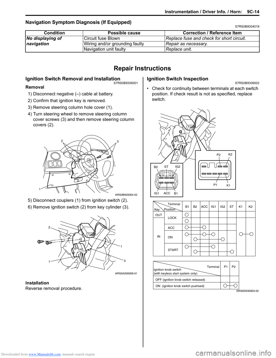
Ignition Switch Removal and InstallationS7RS0B9306001
Removal
1) Disconnect negative (–) cable at battery.
2) Confirm that ignition key is removed.
3) Remove steering column hole cover (1).
4) Turn steering wheel to remove steering column cover screws (3) and then remove steering column
covers (2).
5) Disconnect couplers (1) from ignition switch (2).
6) Remove ignition switch (2) from key cylinder (3).
Installation
Reverse removal procedure.
Ignition Switch InspectionS7RS0B9306002
• Check for continuity between terminals at each switch
position. If check result is not as specified, replace
switch.
Condition Possible cause Correction / Reference Item
No displaying of
navigation Circuit fuse Blown
Replace fuse and check for short circuit.
Wiring and/or grounding faulty Repair as necessary.
Navigation unit faulty Replace unit.
1
32
I4RS0B920004-02
1 1
2
3
I4RS0A930008-01
PositionTerminal
LOCK
ACC
ON
START
OUT
INK2K1ST
IG2
IG1
ACC
B1 B2
Ignition knob switch
(with keyless start system only)
ACC
IG1 IG2
ST
B2
B1 K2
K1
P2
P1
Terminal
OFF (ignition knob switch released) ON (ignition knob switch pushsed)P1 P2
Key
I5RS0D930003-02
Page 1317 of 1496
Downloaded from www.Manualslib.com manuals search engine Instrumentation / Driver Info. / Horn: 9C-22
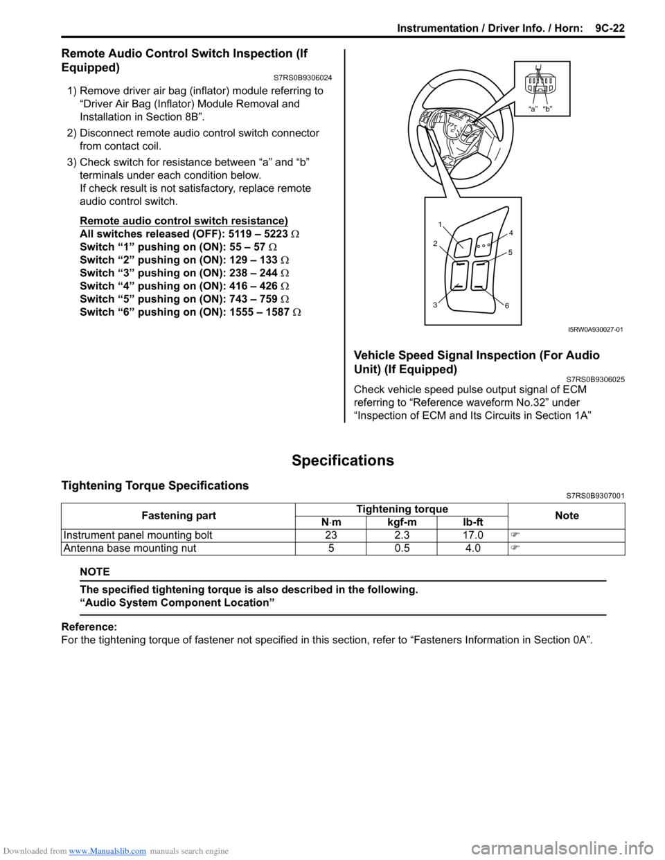
Remote Audio Control Switch Inspection (If
Equipped)
S7RS0B9306024
1) Remove driver air bag (inflator) module referring to
“Driver Air Bag (Inflator) Module Removal and
Installation in Section 8B”.
2) Disconnect remote audio control switch connector
from contact coil.
3) Check switch for resistance between “a” and “b” terminals under each condition below.
If check result is not satisfactory, replace remote
audio control switch.
Remote audio control switch resistance)
All switches released (OFF): 5119 – 5223 Ω
Switch “1” pushing on (ON): 55 – 57 Ω
Switch “2” pushing on (ON): 129 – 133 Ω
Switch “3” pushing on (ON): 238 – 244 Ω
Switch “4” pushing on (ON): 416 – 426 Ω
Switch “5” pushing on (ON): 743 – 759 Ω
Switch “6” pushing on (ON): 1555 – 1587 Ω
Vehicle Speed Signal Inspection (For Audio
Unit) (If Equipped)
S7RS0B9306025
Check vehicle speed pulse output signal of ECM
referring to “Reference waveform No.32” under
“Inspection of ECM and Its Circuits in Section 1A”
Specifications
Tightening Torque SpecificationsS7RS0B9307001
NOTE
The specified tightening torque is also described in the following.
“Audio System Component Location”
Reference:
For the tightening torque of fastener not specified in this section, refer to “Fasteners Information in Section 0A”.
“b”“a”
1
2
3 4
5
6
I5RW0A930027-01
Fastening part Tightening torque
Note
N ⋅mkgf-mlb-ft
Instrument panel mounting bolt 23 2.3 17.0 �)
Antenna base mounting nut 5 0.5 4.0 �)
Page 1329 of 1496
Downloaded from www.Manualslib.com manuals search engine Glass / Windows / Mirrors: 9E-2
• Eyeleteer
• Piano string
• Windshield knife
• Brush for primer application (2 pcs)
•Knife
• Rubber sucker grip
• Sealant gun (for filling adhesive)
• Putty spatula (for correcting adhered parts)
Diagnostic Information and Procedures
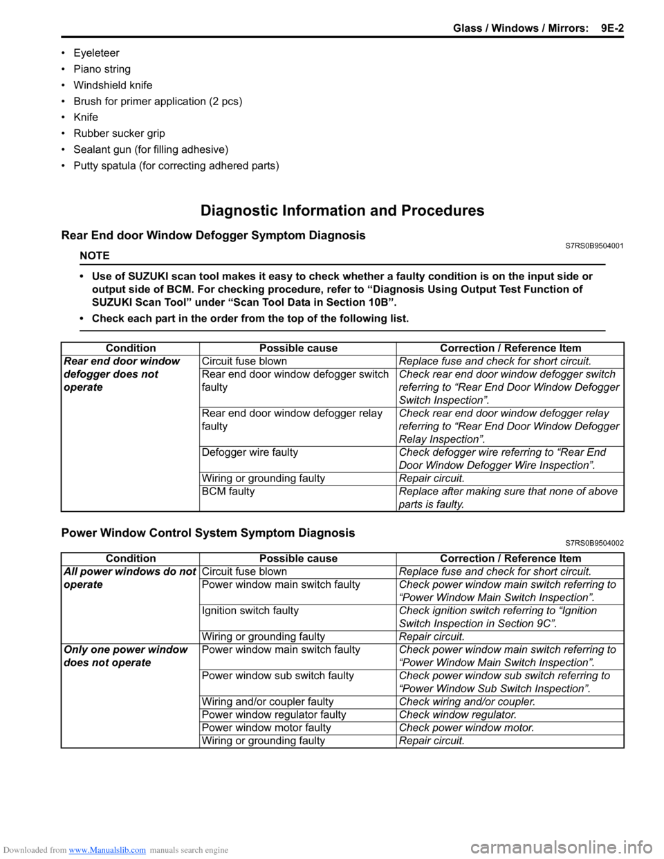
Rear End door Window Defogger Symptom DiagnosisS7RS0B9504001
NOTE
• Use of SUZUKI scan tool makes it easy to check whether a faulty condition is on the input side or
output side of BCM. For checking procedure, re fer to “Diagnosis Using Output Test Function of
SUZUKI Scan Tool” under “Scan Tool Data in Section 10B”.
• Check each part in the order from the top of the following list.
Power Window Control System Symptom DiagnosisS7RS0B9504002
Condition Possible cause Correction / Reference Item
Rear end door window
defogger does not
operate Circuit fuse blown
Replace fuse and check for short circuit.
Rear end door window defogger switch
faulty Check rear end door window defogger switch
referring to “Rear End Door Window Defogger
Switch Inspection”.
Rear end door window defogger relay
faulty Check rear end door window defogger relay
referring to “Rear End Door Window Defogger
Relay Inspection”.
Defogger wire faulty Check defogger wire referring to “Rear End
Door Window Defogger Wire Inspection”.
Wiring or grounding faulty Repair circuit.
BCM faulty Replace after making sure that none of above
parts is faulty.
ConditionPossible cause Correction / Reference Item
All power windows do not
operate Circuit fuse blown
Replace fuse and check for short circuit.
Power window main switch faulty Check power window main switch referring to
“Power Window Main Switch Inspection”.
Ignition switch faulty Check ignition switch referring to “Ignition
Switch Inspection in Section 9C”.
Wiring or grounding faulty Repair circuit.
Only one power window
does not operate Power window main switch faulty
Check power window main switch referring to
“Power Window Main Switch Inspection”.
Power window sub switch faulty Check power window sub switch referring to
“Power Window Sub Switch Inspection”.
Wiring and/or coupler faulty Check wiring and/or coupler.
Power window regulator faulty Check window regulator.
Power window motor faulty Check power window motor.
Wiring or grounding faulty Repair circuit.
Page 1334 of 1496
Downloaded from www.Manualslib.com manuals search engine 9E-7 Glass / Windows / Mirrors:
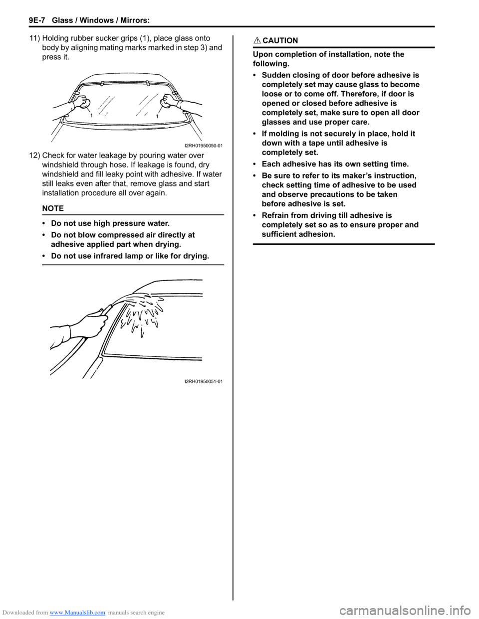
11) Holding rubber sucker grips (1), place glass onto body by aligning mating marks marked in step 3) and
press it.
12) Check for water leakage by pouring water over windshield through hose. If leakage is found, dry
windshield and fill leaky po int with adhesive. If water
still leaks even after that , remove glass and start
installation procedure all over again.
NOTE
• Do not use high pressure water.
• Do not blow compressed air directly at adhesive applied part when drying.
• Do not use infrared lamp or like for drying.
CAUTION!
Upon completion of installation, note the
following.
• Sudden closing of door before adhesive is completely set may cause glass to become
loose or to come off. Therefore, if door is
opened or closed before adhesive is
completely set, make sure to open all door
glasses and use proper care.
• If molding is not securely in place, hold it down with a tape until adhesive is
completely set.
• Each adhesive has its own setting time.
• Be sure to refer to its maker’s instruction, check setting time of adhesive to be used
and observe precautions to be taken
before adhesive is set.
• Refrain from driving till adhesive is completely set so as to ensure proper and
sufficient adhesion.
I2RH01950050-01
I2RH01950051-01
Page 1340 of 1496
Downloaded from www.Manualslib.com manuals search engine 9E-13 Glass / Windows / Mirrors:
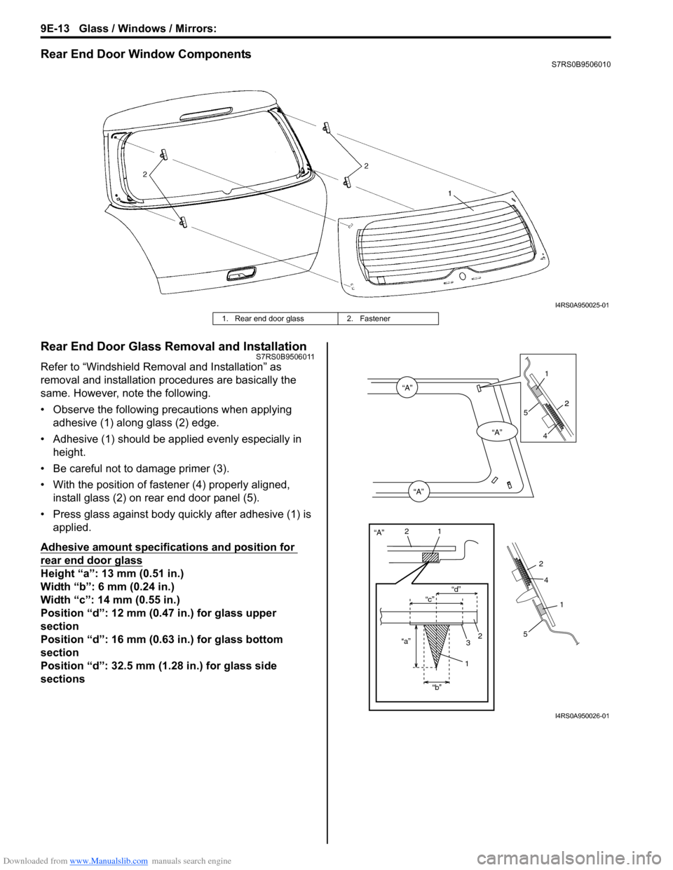
Rear End Door Window ComponentsS7RS0B9506010
Rear End Door Glass Removal and InstallationS7RS0B9506011
Refer to “Windshield Removal and Installation” as
removal and installation procedures are basically the
same. However, note the following.
• Observe the following precautions when applying adhesive (1) along glass (2) edge.
• Adhesive (1) should be app lied evenly especially in
height.
• Be careful not to damage primer (3).
• With the position of fastener (4) properly aligned, install glass (2) on rear end door panel (5).
• Press glass against body quickly after adhesive (1) is applied.
Adhesive amount specifications and position for
rear end door glass
Height “a”: 13 mm (0.51 in.)
Width “b”: 6 mm (0.24 in.)
Width “c”: 14 mm (0.55 in.)
Position “d”: 12 mm (0.47 in.) for glass upper
section
Position “d”: 16 mm (0.63 in.) for glass bottom
section
Position “d”: 32.5 mm (1.28 in.) for glass side
sections
I4RS0A950025-01
1. Rear end door glass 2. Fastener
“A”
“A”
“A”
“A”
“c”“d”
“a” “b”
21
2
3
1
2
1
1
2
5
2
4
4
5
I4RS0A950026-01
Page 1347 of 1496
Downloaded from www.Manualslib.com manuals search engine Security and Locks: 9F-1
Body, Cab and Accessories
Security and Locks
General Description
Key Coding ConstructionS7RS0B9601001
Key Usage and Identification
Key is used for ignition and door lock cylinders. Key is cut on both edges to make them reversible.
Key identification is obtained from five character key code stamped on key code tag. Using this key code, key code
cutting combination can be determined from a code list (ava ilable to owners of key cutting equipment from suppliers).
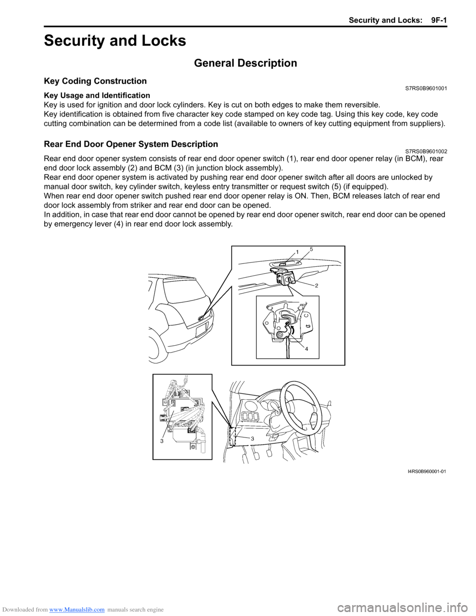
Rear End Door Opener System DescriptionS7RS0B9601002
Rear end door opener system consists of rear end door opener switch (1), rear end door opener relay (in BCM), rear
end door lock assembly (2) and BCM (3) (in junction block assembly).
Rear end door opener system is activated by pushing re ar end door opener switch after all doors are unlocked by
manual door switch, key cylinder s witch, keyless entry transmitter or request switch (5) (if equipped).
When rear end door opener switch pushed rear end door opener relay is ON. Then, BCM releases latch of rear end
door lock assembly from striker and rear end door can be opened.
In addition, in case that rear end door cannot be opened by rear end door opener switch, rear end door can be opened
by emergency lever (4) in rear end door lock assembly.
I4RS0B960001-01