2006 SUZUKI SWIFT egr valve inspection
[x] Cancel search: egr valve inspectionPage 46 of 1496

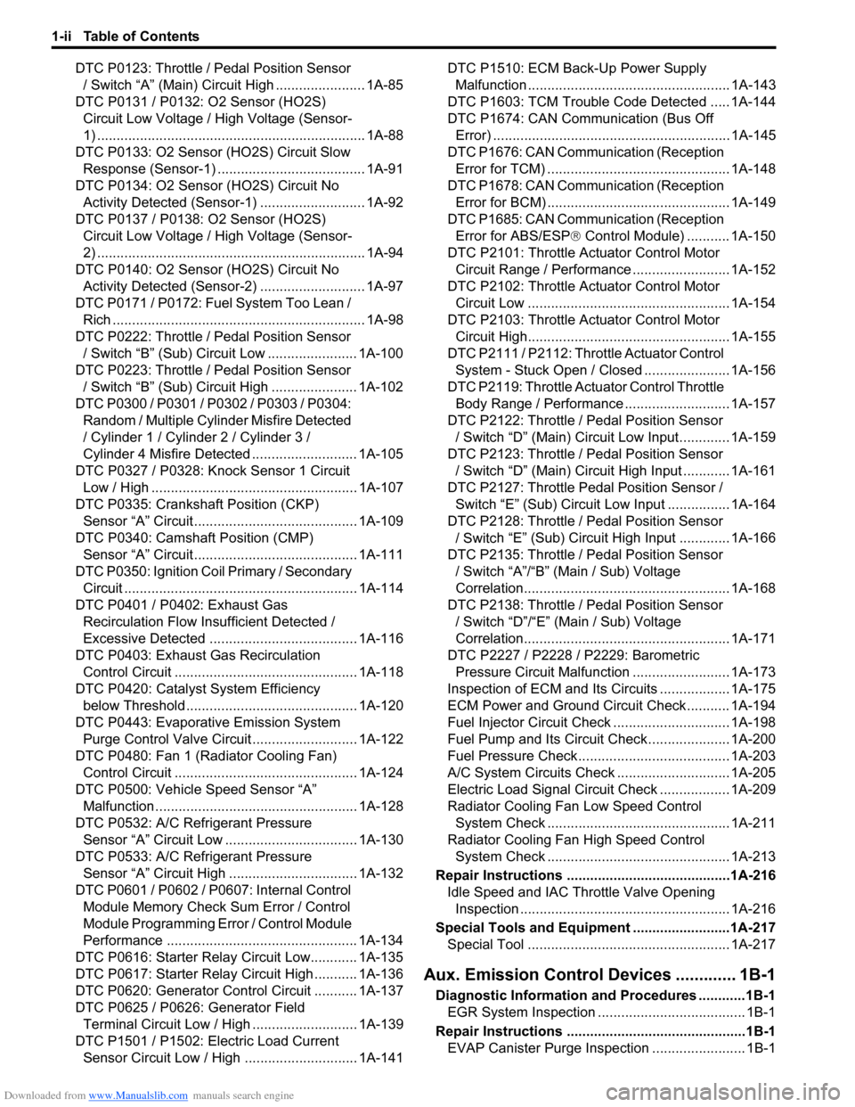
Downloaded from www.Manualslib.com manuals search engine 1-ii Table of Contents
DTC P0123: Throttle / Pedal Position Sensor / Switch “A” (Main) Circuit High ....................... 1A-85
DTC P0131 / P0132: O2 Sensor (HO2S) Circuit Low Voltage / High Voltage (Sensor-
1) ..................................................................... 1A-88
DTC P0133: O2 Sensor (HO2S) Circuit Slow
Response (Sensor- 1) ...................................... 1A-91
DTC P0134: O2 Sensor (HO2S) Circuit No Activity Detected (Sensor -1) ........................... 1A-92
DTC P0137 / P0138: O2 Sensor (HO2S) Circuit Low Voltage / High Voltage (Sensor-
2) ..................................................................... 1A-94
DTC P0140: O2 Sensor (HO2S) Circuit No Activity Detected (Sensor -2) ........................... 1A-97
DTC P0171 / P0172: Fuel System Too Lean / Rich ................................................................. 1A-98
DTC P0222: Throttle / Pedal Position Sensor / Switch “B” (Sub) Circuit Low ....................... 1A-100
DTC P0223: Throttle / Pedal Position Sensor / Switch “B” (Sub) Circuit High ...................... 1A-102
DTC P0300 / P0301 / P0302 / P0303 / P0304: Random / Multiple Cylin der Misfire Detected
/ Cylinder 1 / Cylinder 2 / Cylinder 3 /
Cylinder 4 Misfire Detected ........................... 1A-105
DTC P0327 / P0328: Knoc k Sensor 1 Circuit
Low / High ..................................................... 1A-107
DTC P0335: Crankshaft Position (CKP) Sensor “A” Circuit .......................................... 1A-109
DTC P0340: Camshaft Position (CMP) Sensor “A” Circuit .......................................... 1A-111
DTC P0350: Ignition Coil Primary / Secondary Circuit ............................................................ 1A-114
DTC P0401 / P0402: Exhaust Gas Recirculation Flow Insufficient Detected /
Excessive Detected ...................................... 1A-116
DTC P0403: Exhaust Gas Recirculation Control Circuit ................... ............................ 1A-118
DTC P0420: Catalyst System Efficiency
below Threshold ................ ............................ 1A-120
DTC P0443: Evaporativ e Emission System
Purge Control Valve Circuit ........................... 1A-122
DTC P0480: Fan 1 (Radiator Cooling Fan) Control Circuit ................... ............................ 1A-124
DTC P0500: Vehicle Speed Sensor “A” Malfunction .................................................... 1A-128
DTC P0532: A/C Refrigerant Pressure Sensor “A” Circuit Low ... ............................... 1A-130
DTC P0533: A/C Refrigerant Pressure Sensor “A” Circuit High ................................. 1A-132
DTC P0601 / P0602 / P0607: Internal Control Module Memory Check Sum Error / Control
Module Programming Error / Control Module
Performance ................................................. 1A-134
DTC P0616: Starter Relay Circuit Low............ 1A-135
DTC P0617: Starter Relay Circuit High ........... 1A-136
DTC P0620: Generator Control Circuit ........... 1A-137
DTC P0625 / P0626: Generator Field Terminal Circuit Low / High . .......................... 1A-139
DTC P1501 / P1502: Electric Load Current Sensor Circuit Low / High . ............................ 1A-141 DTC P1510: ECM Back-Up Power Supply
Malfunction .................................................... 1A-143
DTC P1603: TCM Trouble Code Detected ..... 1A-144
DTC P1674: CAN Communication (Bus Off Error) ............................................................. 1A-145
DTC P1676: CAN Communication (Reception Error for TCM) ............................................... 1A-148
DTC P1678: CAN Communication (Reception Error for BCM) ............................................... 1A-149
DTC P1685: CAN Communication (Reception Error for ABS/ESP ® Control Module) ........... 1A-150
DTC P2101: Throttle Actuator Control Motor Circuit Range / Performance ......................... 1A-152
DTC P2102: Throttle Actuator Control Motor Circuit Low .................................................... 1A-154
DTC P2103: Throttle Actuator Control Motor Circuit High.................................................... 1A-155
DTC P2111 / P2112: Throttle Actuator Control System - Stuck Open / Closed ...................... 1A-156
DTC P2119: Throttle Actu ator Control Throttle
Body Range / Performance ........................... 1A-157
DTC P2122: Throttle / Pedal Position Sensor / Switch “D” (Main) Circuit Low Input............. 1A-159
DTC P2123: Throttle / Pedal Position Sensor / Switch “D” (Main) Circuit High Input ............ 1A-161
DTC P2127: Throttle Pedal Position Sensor / Switch “E” (Sub) Circuit Low Input ................ 1A-164
DTC P2128: Throttle / Pedal Position Sensor
/ Switc
h “E” (Sub) Circuit High Input ............. 1A-166
DTC P2135: Throttle / Pedal Position Sensor / Switch “A”/“B” (Main / Sub) Voltage
Correlation..................................................... 1A-168
DTC P2138: Throttle / Pedal Position Sensor / Switch “D”/“E” (Main / Sub) Voltage
Correlation..................................................... 1A-171
DTC P2227 / P2228 / P2229: Barometric Pressure Circuit Malfunction ......................... 1A-173
Inspection of ECM and Its Circuits .................. 1A-175
ECM Power and Ground Circuit Check........... 1A-194
Fuel Injector Circuit Check .............................. 1A-198
Fuel Pump and Its Circuit Check..................... 1A-200
Fuel Pressure Check....................................... 1A-203
A/C System Circuits Check ............................. 1A-205
Electric Load Signal Circuit Check .................. 1A-209
Radiator Cooling Fan Low Speed Control System Check ............................................... 1A-211
Radiator Cooling Fan High Speed Control System Check ............................................... 1A-213
Repair Instructions ......... .................................1A-216
Idle Speed and IAC Throttle Valve Opening Inspection ...................................................... 1A-216
Special Tools and Equipmen t .........................1A-217
Special Tool .................................................... 1A-217
Aux. Emission Control Devices ............. 1B-1
Diagnostic Information and Procedures ............1B-1
EGR System Inspection ...................................... 1B-1
Repair Instructions ............ ..................................1B-1
EVAP Canister Purge Inspec tion ........................ 1B-1
Page 47 of 1496

Downloaded from www.Manualslib.com manuals search engine Table of Contents 1-iii
EVAP Canister Purge Valve and Its Circuit
Inspection.......................................................... 1B-2
Vacuum Passage Inspection .............................. 1B-3
Vacuum Hose and Purge Valve Chamber Inspection.......................................................... 1B-3
EVAP Canister Purge Valve Inspection .............. 1B-3
EVAP Canister Inspection ... ................................ 1B-4
EGR Valve Removal and Installation .................. 1B-4
EGR Valve Inspection ......................................... 1B-4
PCV Hose Inspection .......................................... 1B-4
PCV Valve Inspection ......................................... 1B-5
Special Tools and Equipmen t ............................. 1B-5
Special Tool ........................................................ 1B-5
Engine Electrical Devices .. ..................... 1C-1
Repair Instructions .............................................. 1C-1
ECM Removal and Installation ............................ 1C-1
MAP Sensor Inspection ...................................... 1C-2
Electric Throttle Body Assembly On-Vehicle
Inspection.......................................................... 1C-2
Electric Throttle Body System Calibration ........... 1C-5
APP Sensor Assembly On-V ehicle Inspection .... 1C-5
APP Sensor Assembly Removal and Installation ......................................................... 1C-5
APP Sensor Assembly Inspection ...................... 1C-6
ECT Sensor Removal and In stallation ................ 1C-6
ECT Sensor Inspection ....................................... 1C-7
HO2S-1 and HO2S-2 Heater On-Vehicle Inspection.......................................................... 1C-7
HO2S-1 and HO2S-2 Removal and Installation ......................................................... 1C-7
CMP Sensor Removal and In stallation ............... 1C-8
Camshaft Position (CMP) Se nsor Inspection ...... 1C-8
CKP Sensor Removal and Installation ................ 1C-9
CKP Sensor Inspection ....................................... 1C-9
Knock Sensor Removal and Installation ........... 1C-10
Main Relay, Fuel Pump Relay and Starting
Motor Control Relay Inspection....................... 1C-10
MAF and IAT Sensor On-Vehicle Inspection .... 1C-11
MAF and IAT Sensor Removal and Installation ....................................................... 1C-11
MAF and IAT Sensor Inspection ....................... 1C-12
Electric Load Current Sensor On-Vehicle Inspection........................................................ 1C-12
Specifications ..................................................... 1C-13
Tightening Torque Specifications ...................... 1C-13
Engine Mechanical ......... ......................... 1D-1
General Description ............................................. 1D-1
Engine Construction Description ......................... 1D-1
Camshaft Position Control (VVT Variable Valve Timing) System Description .................... 1D-2
Diagnostic Information and Procedures ............ 1D-4 Compression Check ............................................ 1D-4
Engine Vacuum Check ....................................... 1D-5
Valve Lash (Clearance) Inspection ..................... 1D-6
Repair Instructions .............................................. 1D-9 Air Cleaner Components ..................................... 1D-9
Air Cleaner Element Removal and Installation .... 1D-9 Air Cleaner Element Ins
pection and Cleaning ..1D-10
Cylinder Head Co ver Removal and
Installation .......................................................1D-10
Throttle Body and Intake Manifold
Components ....................................................1D-12
Throttle Body On-Vehicle Inspection.................1D-13
Electric Throttle Body Assembly Removal and Installation .......................................................1D-13
Throttle Body Cleaning......................................1D-14
Intake Manifold Removal and Installation .........1D-14
Engine Mountings Components ........................1D-16
Engine Assembly Removal and Installation ......1D-17
Timing Chain Cover Components .....................1D-20
Timing Chain Cover Removal and Installation ..1D-21
Timing Chain Cover Inspection .........................1D-23
Oil Control Valve Removal and Installation .......1D-23
Oil Control Valve Inspection ..............................1D-24
Timing Chain and Chain Tensioner Components ....................................................1D-24
Timing Chain and Chain Tensioner Removal and Installation ................................................1D-25
Timing Chain and Chain Tensioner Inspection ..1D-27
Camshaft, Tappet and Shim Components ........1D-28
Camshaft, Tappet and Shim Removal and Installation .......................................................1D-29
Camshaft, Tappet and Shim Inspection ............1D-31
Valves and Cylinder Head Components ...........1D-34
Valves and Cylinder Head Removal and
Installation .......................................................1D-35
Valves and Cylinder Head Disassembly and Assembly.........................................................1D-37
Valves and Valve Guides Inspection.................1D-40
Cylinder Head Inspection . .................................1D-42
Valve Spring Inspection ....................................1D-43
Pistons, Piston Rings , Connecting Rods and
Cylinders Components ....................................1D-44
Pistons, Piston Rings , Connecting Rods and
Cylinders Removal and Installation .................1D-45
Pistons, Piston Rings , Connecting Rods and
Cylinders Disassembly and Assembly ............1D-46
Cylinders, Pistons and Piston Rings Inspection ........................................................1D-47
Piston Pins and Connecting Rods Inspection ...1D-49
Crank Pin and Connecting Rod Bearings Inspection ........................................................1D-50
Main Bearings, Cran kshaft and Cylinder
Block Components ..........................................1D-53
Main Bearings, Cran kshaft and Cylinder
Block Removal and Installa tion .......................1D-54
Crankshaft Inspection .......................................1D-57
Main Bearings Inspection . .................................1D-59
Sensor Plate Inspection ....................................1D-63
Rear Oil Seal Inspection ...................................1D-63
Flywheel Inspection...........................................1D-63
Cylinder Block Inspection ..................................1D-63
Specifications .................... .................................1D-64
Tightening Torque Specifications ......................1D-64
Special Tools and Equipmen t ...........................1D-66
Recommended Service Material .......................1D-66
Special Tool ......................................................1D-66
Page 84 of 1496

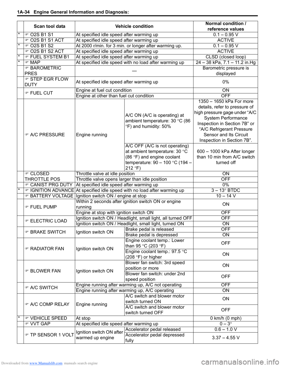
Downloaded from www.Manualslib.com manuals search engine 1A-34 Engine General Information and Diagnosis:
*�) O2S B1 S1 At specified idle speed after warming up 0.1 – 0.95 V
�) O2S B1 S1 ACT At specified id le speed after warming up ACTIVE
* �) O2S B1 S2 At 2000 r/min. for 3 min. or longer after warming up. 0.1 – 0.95 V
�) O2S B1 S2 ACT At specified id le speed after warming up ACTIVE
* �) FUEL SYSTEM B1 At specif ied idle speed after warming up CLSD (closed loop)
* �) MAP At specified idle speed with no load after warming up 24 – 38 kPa, 7.1 – 11.2 in.Hg
�) BAROMETRIC
PRES —Barometric pressure is
displayed
�) STEP EGR FLOW
DUTY At specified idle speed after warming up 0%
�) FUEL CUT Engine at fuel cut condition ON
Engine at other than fuel cut condition OFF
�) A/C PRESSURE Engine running A/C ON (A/C is operating) at
ambient temperature: 30
°C (86
° F) and humidity: 50% 1350 – 1650 kPa For more
details, refer to pressure of
high pressure gage under “A/C System Performance
Inspection in Section 7B” or “A/C Refrigerant Pressure Sensor and Its Circuit
Inspection in Section 7B”.
A/C OFF (A/C is not operating)
at ambient temperature: 30 ° C
(86 °F) and engine coolant
temperature: 90 – 100 °C (194 –
212 °F) 600 – 1000 kPa After longer
than 10 min from A/C switch turned off
�) CLOSED
THROTTLE POS Throttle valve at idle position ON
Throttle valve opens larger than idle position OFF
�) CANIST PRG DUTY At specified idle speed after warming up 0%
* �) IGNITION ADVANCE At specified idle s peed with no load after warming up 3 – 13 ° BTDC
�) BATTERY VOLTAGE Ignition switch ON / engine at stop 10 – 14 V
�) FUEL PUMP Within 2 seconds after ignition switch ON or engine
running
ON
Engine at stop with ignition switch ON OFF
�) ELECTRIC LOAD Ignition switch ON / Headligh
t, small light, all turned OFF OFF
Ignition switch ON / Headli ght, small light, turned ON ON
�) BRAKE SWITCH Igni tion switch ONBrake pedal is released OFF
Brake pedal is depressed ON
�) RADIATOR FAN Ignition switch ON Engin
e coolant temp.: Lower
than 95 °C (203 °F) OFF
Engine coolant temp.: 97.5 °C
(208 °F) or higher ON
�) BLOWER FAN Ignition switch ON Blower fan switch: 3rd speed
position or more
ON
Blower fan switch: under 2nd
speed position OFF
�) A/C SWITCH Engine running after warming up, A/C not operating
OFF
Engine running after warming up, A/C operating ON
�) A/C COMP RELAY Engine running A/C switch and blower motor
switch turned ON
ON
A/C switch and blower motor
switch turned OFF OFF
* �) VEHICLE SPEED At stop 0 km/h (0 mph)
�) VVT GAP At specified idle speed after warming up 0 – 3°
�) TP SENSOR 1 VOLT Ignition switch ON after
warmed up engine Accelerator pedal released
0.6 – 1.0 V
Accelerator pedal depressed
fully 3.37 – 4.55 V
Scan tool data
Vehicle condition Normal condition /
reference values
Page 91 of 1496

Downloaded from www.Manualslib.com manuals search engine Engine General Information and Diagnosis: 1A-41
Engine Symptom DiagnosisS7RS0B1104010
Perform troubleshooting referring to the followings when ECM has detected no DTC and no abnormality has been
found in “Visual Inspection” and “Engine Basic Inspection”.
Condition Possible cause Correction / Reference Item
Hard starting (Engine
cranks OK) Faulty spark plug
“Spark Plug Inspection in Section 1H”
Leaky high-tension cord “High-Tension Cord Inspection in Section 1H”
Loose connection or disconnection of
high-tension cord(s) or lead wire(s) “High-Tension Cord Removal and Installation
in Section 1H”
Faulty ignition coil “Ignition Coil Assembly (Including ignitor)
Inspection in Section 1H”
Dirty or clogged fuel hose or pipe “Fuel Pressure Check”
Malfunctioning fuel pump “Fuel Pressure Check”
Air drawn in through intake manifold
gasket or throttle body gasket
Faulty electric throttle body assembly “Electric Throttle Body Assembly On-Vehicle
Inspection in Section 1C”
Faulty APP sensor assembly “APP Sensor Assembly Inspection in Section
1C”
Faulty ECT sensor or MAF sensor “ECT Sensor Inspection in Section 1C” or
“MAF and IAT Sensor Inspection in Section
1C”
Faulty ECM
Low compression “Compression Check in Section 1D”
Poor spark plug tightening or faulty
gasket “Spark Plug Removal and Installation in
Section 1H”
Compression leak from valve seat “Valves and Valve Guides Inspection in
Section 1D”
Sticky valve stem “Valves and Valve Guides Inspection in
Section 1D”
Weak or damaged valve springs “Valve Spring Inspection in Section 1D”
Compression leak at cylinder head
gasket “Cylinder Head Inspection in Section 1D”
Sticking or damaged piston ring “Cylinders, Pistons and Piston Rings
Inspection in Section 1D”
Worn piston, ring or cylinder “Cylinders, Pistons and Piston Rings
Inspection in Section 1D”
Malfunctioning PCV valve “PCV Valve Inspection in Section 1B”
Camshaft position control (VVT) system
out of order “Oil Control Valve Inspection in Section 1D”
Faulty EGR system “EGR System Inspection in Section 1B”
Low oil pressure Improper oil viscosity “Engine Oil and Filter Change in Section 0B”
Malfunctioning oil pressure switch “Oil Pressure Switch Inspection in Section 9C”
Clogged oil strainer “Oil Pan and Oil Pump Strainer Cleaning in
Section 1E”
Functional deterioration of oil pump “Oil Pump Inspection in Section 1E”
Worn oil pump relief valve “Oil Pump Inspection in Section 1E”
Excessive clearance in various sliding
parts
Engine noise – Valve
noise
NOTE
Before checking
mechanical noise, make
sure that:
• Specified spark plug is used.
• Specified fuel is used.
Improper valve lash “Camshaft, Tappet and Shim Inspection in
Section 1D”
Worn valve stem and guide “Valves and Valve Guides Inspection in
Section 1D”
Weak or broken valve spring “Valve Spring Inspection in Section 1D”
Warped or bent valve “Valves and Valve Guides Inspection in
Section 1D”
Page 93 of 1496

Downloaded from www.Manualslib.com manuals search engine Engine General Information and Diagnosis: 1A-43
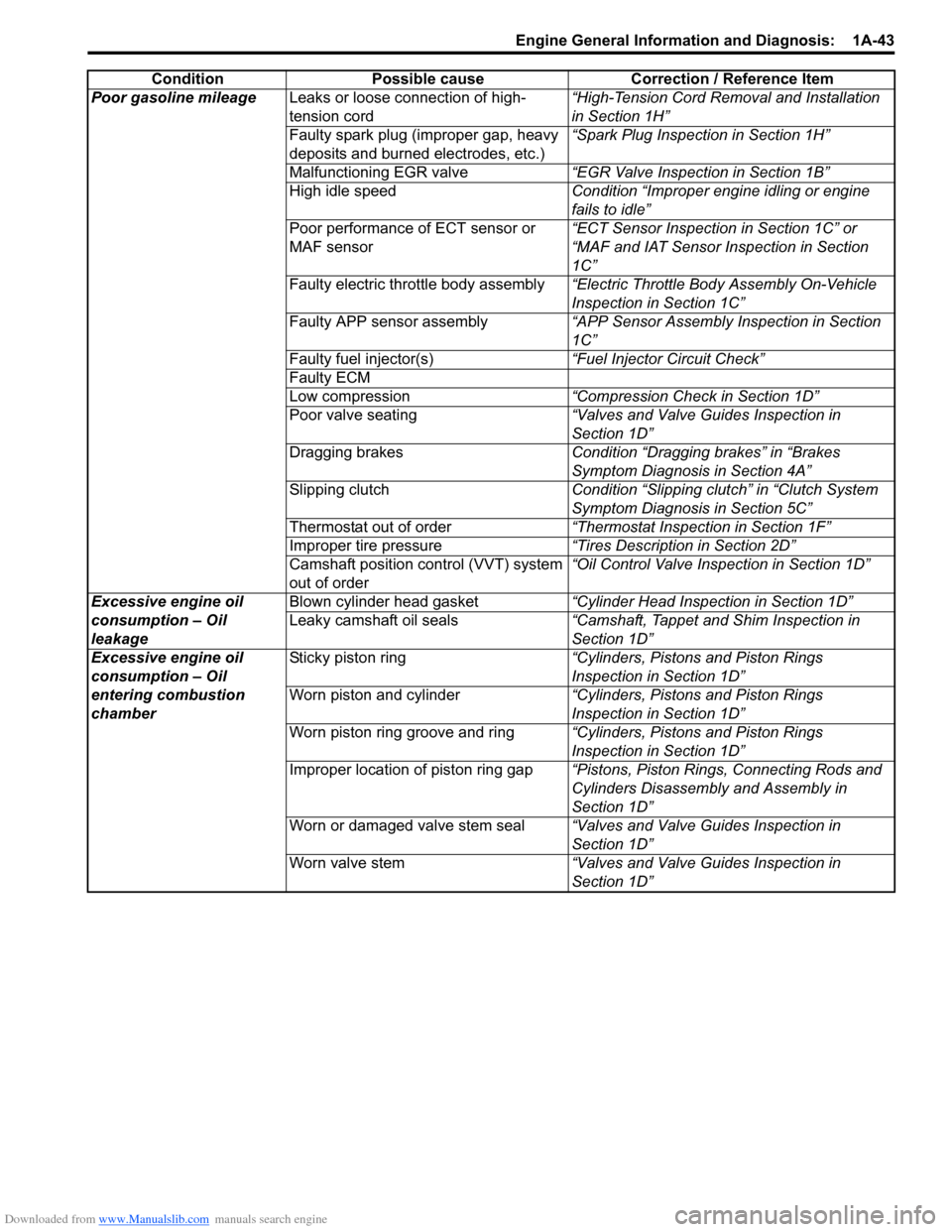
Poor gasoline mileageLeaks or loose connection of high-
tension cord “High-Tension Cord Removal and Installation
in Section 1H”
Faulty spark plug (improper gap, heavy
deposits and burned electrodes, etc.) “Spark Plug Inspection in Section 1H”
Malfunctioning EGR valve “EGR Valve Inspection in Section 1B”
High idle speed Condition “Improper engine idling or engine
fails to idle”
Poor performance of ECT sensor or
MAF sensor “ECT Sensor Inspection in Section 1C” or
“MAF and IAT Sensor Inspection in Section
1C”
Faulty electric throttle body assembly “Electric Throttle Body Assembly On-Vehicle
Inspection in Section 1C”
Faulty APP sensor assembly “APP Sensor Assembly Inspection in Section
1C”
Faulty fuel injector(s) “Fuel Injector Circuit Check”
Faulty ECM
Low compression “Compression Check in Section 1D”
Poor valve seating “Valves and Valve Guides Inspection in
Section 1D”
Dragging brakes Condition “Dragging brakes” in “Brakes
Symptom Diagnosis in Section 4A”
Slipping clutch Condition “Slipping clutch” in “Clutch System
Symptom Diagnosis in Section 5C”
Thermostat out of order “Thermostat Inspection in Section 1F”
Improper tire pressure “Tires Description in Section 2D”
Camshaft position control (VVT) system
out of order “Oil Control Valve Inspection in Section 1D”
Excessive engine oil
consumption – Oil
leakage Blown cylinder head gasket
“Cylinder Head Inspection in Section 1D”
Leaky camshaft oil seals “Camshaft, Tappet and Shim Inspection in
Section 1D”
Excessive engine oil
consumption – Oil
entering combustion
chamber Sticky piston ring
“Cylinders, Pistons and Piston Rings
Inspection in Section 1D”
Worn piston and cylinder “Cylinders, Pistons and Piston Rings
Inspection in Section 1D”
Worn piston ring groove and ring “Cylinders, Pistons and Piston Rings
Inspection in Section 1D”
Improper location of piston ring gap “Pistons, Piston Rings, Connecting Rods and
Cylinders Disassembly and Assembly in
Section 1D”
Worn or damaged valve stem seal “Valves and Valve Guides Inspection in
Section 1D”
Worn valve stem “Valves and Valve Guides Inspection in
Section 1D”
Condition Possible cause Correction / Reference Item
Page 94 of 1496

Downloaded from www.Manualslib.com manuals search engine 1A-44 Engine General Information and Diagnosis:
Engine hesitates –
Momentary lack of
response as accelerator
is depressed. Can occur
at all vehicle speeds.
Usually most severe when
first trying to make
vehicle move, as from a
stop sign.Spark plug faulty
“Spark Plug Inspection in Section 1H”
Leaky high-tension cord “High-Tension Cord Inspection in Section 1H”
Fuel pressure out of specification “Fuel Pressure Check”
Malfunctioning EGR valve “EGR Valve Inspection in Section 1B”
Poor performance of ECT sensor or
MAF sensor “ECT Sensor Inspection in Section 1C” or
“MAF and IAT Sensor Inspection in Section
1C”
Faulty electric throttle body assembly “Electric Throttle Body Assembly On-Vehicle
Inspection in Section 1C”
Faulty APP sensor assembly “APP Sensor Assembly Inspection in Section
1C”
Faulty fuel injector “Fuel Injector Circuit Check”
Faulty ECM
Engine overheating Condition “Engine overheating”
Low compression “Compression Check in Section 1D”
Camshaft position control (VVT) system
out of order “Oil Control Valve Inspection in Section 1D”
Surge – Engine power
variation under steady
throttle or cruise. Feels
like vehicle speeds up
and down with no change
in accelerator pedal. Leaky or loosely connected high-tension
cord
“High-Tension Cord Removal and Installation
in Section 1H”
Faulty spark plug (excess carbon
deposits, improper gap, burned
electrodes, etc.) “Spark Plug Inspection in Section 1H”
Variable fuel pressure “Fuel Pressure Check”
Kinky or damaged fuel hose and lines
Faulty fuel pump (clogged fuel filter)
Malfunctioning EGR valve “EGR Valve Inspection in Section 1B”
Poor performance of MAF sensor “MAF and IAT Sensor Inspection in Section
1C”
Faulty fuel injector “Fuel Injector Circuit Check”
Faulty electric throttle body assembly “Electric Throttle Body Assembly On-Vehicle
Inspection in Section 1C”
Faulty APP sensor assembly “APP Sensor Assembly Inspection in Section
1C”
Faulty ECM
Excessive detonation –
Engine makes
continuously sharp
metallic knocks that
change with throttle
opening. Sounds like pop
corn popping. Faulty spark plug
“Spark Plug Inspection in Section 1H”
Loose connection of high-tension cord “High-Tension Cord Removal and Installation
in Section 1H”
Engine overheating Condition “Engine overheating”
Clogged fuel filter (faulty fuel pump) or
fuel lines “Fuel Pressure Check” or “Fuel Pump and Its
Circuit Check”
Air drawn in through intake manifold or
throttle body gasket
Malfunctioning EGR valve “EGR Valve Inspection in Section 1B”
Poor performance of knock sensor, ECT
sensor or MAF sensor “DTC P0327 / P0328: Knock Sensor 1 Circuit
Low / High”, “ECT Sensor Inspection in
Section 1C” or “MAF and IAT Sensor
Inspection in Section 1C”
Faulty fuel injector(s) “Fuel Injector Circuit Check”
Faulty ECM
Excessive combustion chamber
deposits “Cylinders, Pistons and Piston Rings
Inspection in Section 1D” and/or “Piston Pins
and Connecting Rods In
spection in Section
1D”
Camshaft position control (VVT) system
out of order “Oil Control Valve Inspection in Section 1D”
Condition Possible cause Correction / Reference Item
Page 95 of 1496

Downloaded from www.Manualslib.com manuals search engine Engine General Information and Diagnosis: 1A-45
Engine has no powerFaulty spark plug “Spark Plug Inspection in Section 1H”
Faulty ignition coil with ignitor “Ignition Coil Assembly (Including ignitor)
Inspection in Section 1H”
Leaks, loose connection or
disconnection of high-tension cord “High-Tension Cord Removal and Installation
in Section 1H”
Faulty knock sensor “DTC P0327 / P0328: Knock Sensor 1 Circuit
Low / High”
Clogged fuel hose or pipe “Fuel Pressure Check”
Malfunctioning fuel pump “Fuel Pump and Its Circuit Check”
Air drawn in through intake manifold
gasket or throttle body gasket
Engine overheating Condition “Engine overheating”
Malfunctioning EGR valve “EGR Valve Inspection in Section 1B”
Poor performance of ECT sensor or
MAF sensor “ECT Sensor Inspection in Section 1C” or
“MAF and IAT Sensor Inspection in Section
1C”
Faulty electric throttle body assembly “Electric Throttle Body Assembly On-Vehicle
Inspection in Section 1C”
Faulty APP sensor assembly “APP Sensor Assembly Inspection in Section
1C”
Faulty fuel injector(s) “Fuel Injector Circuit Check”
Faulty ECM
Dragging brakes Condition “Dragging brakes” in “Brakes
Symptom Diagnosis in Section 4A”
Slipping clutch Condition “Slipping clutch” in “Clutch System
Symptom Diagnosis in Section 5C”
Low compression “Compression Check in Section 1D”
Camshaft position control (VVT) system
out of order “Oil Control Valve Inspection in Section 1D”
Improper engine idling or
engine fails to idle Faulty spark plug
“Spark Plug Inspection in Section 1H”
Leaky or disconnected high-tension cord “High-Tension Cord Removal and Installation
in Section 1H”
Faulty ignition coil with ignitor “Ignition Coil Assembly (Including ignitor)
Inspection in Section 1H”
Fuel pressure out of specification “Fuel Pressure Check”
Leaky manifold, throttle body, or cylinder
head gasket
Malfunctioning EGR valve “EGR Valve Inspection in Section 1B”
Faulty evaporative emission control
system “EVAP Canister Purge Inspection in Section
1B”
Faulty EGR system “EGR System Inspection in Section 1B”
Faulty fuel injector(s) “Fuel Injector Circuit Check”
Poor performance of ECT sensor or
MAF sensor “ECT Sensor Inspection in Section 1C” or
“MAF and IAT Sensor Inspection in Section
1C”
Faulty electric throttle body assembly “Electric Throttle Body Assembly On-Vehicle
Inspection in Section 1C”
Faulty APP sensor assembly “APP Sensor Assembly Inspection in Section
1C”
Faulty ECM
Loose connection or disconnection of
vacuum hoses
Malfunctioning PCV valve “PCV Valve Inspection in Section 1B”
Engine overheating Condition “Engine overheating”
Low compression “Compression Check in Section 1D”
Camshaft position control (VVT) system
out of order “Oil Control Valve Inspection in Section 1D”
Condition Possible cause Correction / Reference Item
Page 96 of 1496

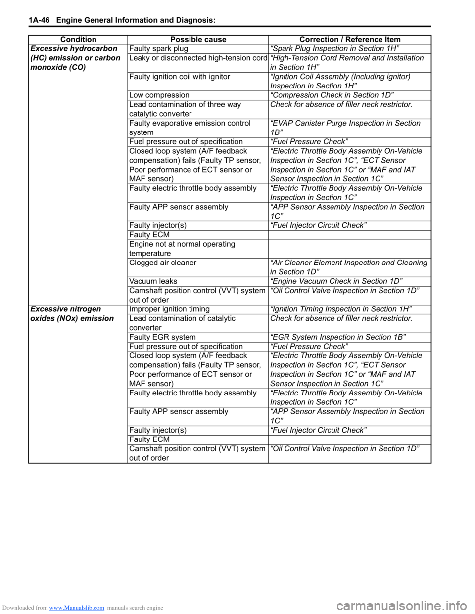
Downloaded from www.Manualslib.com manuals search engine 1A-46 Engine General Information and Diagnosis:
Excessive hydrocarbon
(HC) emission or carbon
monoxide (CO)Faulty spark plug
“Spark Plug Inspection in Section 1H”
Leaky or disconnected high-tension cord “High-Tension Cord Removal and Installation
in Section 1H”
Faulty ignition coil with ignitor “Ignition Coil Assembly (Including ignitor)
Inspection in Section 1H”
Low compression “Compression Check in Section 1D”
Lead contamination of three way
catalytic converter Check for absence of f
iller neck restrictor.
Faulty evaporative emission control
system “EVAP Canister Purge Inspection in Section
1B”
Fuel pressure out of specification “Fuel Pressure Check”
Closed loop system (A/F feedback
compensation) fails (Faulty TP sensor,
Poor performance of ECT sensor or
MAF sensor) “Electric Throttle Body Assembly On-Vehicle
Inspection in Section 1C”, “ECT Sensor
Inspection in Section 1C” or “MAF and IAT
Sensor Inspection in Section 1C”
Faulty electric throttle body assembly “Electric Throttle Body Assembly On-Vehicle
Inspection in Section 1C”
Faulty APP sensor assembly “APP Sensor Assembly Inspection in Section
1C”
Faulty injector(s) “Fuel Injector Circuit Check”
Faulty ECM
Engine not at normal operating
temperature
Clogged air cleaner “Air Cleaner Element Inspection and Cleaning
in Section 1D”
Vacuum leaks “Engine Vacuum Check in Section 1D”
Camshaft position control (VVT) system
out of order “Oil Control Valve Inspection in Section 1D”
Excessive nitrogen
oxides (NOx) emission Improper ignition timing
“Ignition Timing Inspection in Section 1H”
Lead contamination of catalytic
converter Check for absence of f
iller neck restrictor.
Faulty EGR system “EGR System Inspection in Section 1B”
Fuel pressure out of specification “Fuel Pressure Check”
Closed loop system (A/F feedback
compensation) fails (Faulty TP sensor,
Poor performance of ECT sensor or
MAF sensor) “Electric Throttle Body Assembly On-Vehicle
Inspection in Section 1C”, “ECT Sensor
Inspection in Section 1C” or “MAF and IAT
Sensor Inspection in Section 1C”
Faulty electric throttle body assembly “Electric Throttle Body Assembly On-Vehicle
Inspection in Section 1C”
Faulty APP sensor assembly “APP Sensor Assembly Inspection in Section
1C”
Faulty injector(s) “Fuel Injector Circuit Check”
Faulty ECM
Camshaft position control (VVT) system
out of order “Oil Control Valve Inspection in Section 1D”
Condition Possible cause Correction / Reference Item