2006 SUZUKI SWIFT disassembly
[x] Cancel search: disassemblyPage 840 of 1496
Downloaded from www.Manualslib.com manuals search engine 5B-26 Manual Transmission/Transaxle:
Input Shaft Assembly Disassembly and
Reassembly
S7RS0B5206019
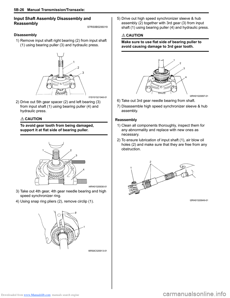
Disassembly1) Remove input shaft right bearing (2) from input shaft (1) using bearing puller (3) and hydraulic press.
2) Drive out 5th gear spacer (2) and left bearing (3) from input shaft (1) using bearing puller (4) and
hydraulic press.
CAUTION!
To avoid gear tooth from being damaged,
support it at flat side of bearing puller.
3) Take out 4th gear, 4th gear needle bearing and high speed synchronizer ring.
4) Using snap ring pliers (2), remove circlip (1). 5) Drive out high speed synchronizer sleeve & hub
assembly (2) together with 3rd gear (3) from input
shaft (1) using bearing puller (4) and hydraulic press.
CAUTION!
Make sure to use flat side of bearing puller to
avoid causing damage to 3rd gear tooth.
6) Take out 3rd gear needle bearing from shaft.
7) Disassemble high speed synchronizer sleeve & hub assembly.
Reassembly 1) Clean all components thoroughly, inspect them for any abnormality and replace with new ones as
necessary.
2) To ensure lubrication of input shaft (1), air blow oil holes (2) and make sure that they are free from any
obstruction.
IYSY01521048-01
1 2
3
4
I4RH01520030-01
I6RS0C520013-01
I2RH01520097-01
I2RH01520049-01
Page 842 of 1496
Downloaded from www.Manualslib.com manuals search engine 5B-28 Manual Transmission/Transaxle:
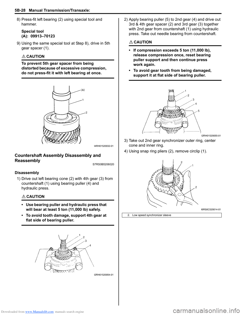
8) Press-fit left bearing (2) using special tool and hammer.
Special tool
(A): 09913–70123
9) Using the same special tool at Step 8), drive in 5th
gear spacer (1).
CAUTION!
To prevent 5th gear spacer from being
distorted because of excessive compression,
do not press-fit it with left bearing at once.
Countershaft Assembly Disassembly and
Reassembly
S7RS0B5206020
Disassembly
1) Drive out left bearing cone (2) with 4th gear (3) from countershaft (1) using bearing puller (4) and
hydraulic press.
CAUTION!
• Use bearing puller and hydraulic press that will bear at least 5 ton (11,000 lb) safely.
• To avoid tooth damage, support 4th gear at flat side of bearing puller.
2) Apply bearing puller (5) to 2nd gear (4) and drive out 3rd & 4th gear spacer (2) and 3rd gear (3) together
with 2nd gear from countershaft (1) using hydraulic
press. Take out needle bearing from countershaft.
CAUTION!
• If compression exceeds 5 ton (11,000 lb), release compression once, reset bearing
puller support and then continue press
work again.
• To avoid gear tooth from being damaged, support it at flat side of bearing puller.
3) Take out 2nd gear synchronizer outer ring, center cone and inner ring.
4) Using snap ring pliers (2), remove circlip (1).
I4RH01520032-01
I2RH01520054-01
2. Low speed synchronizer sleeve
I2RH01520055-01
I6RS0C520014-01
Page 846 of 1496
Downloaded from www.Manualslib.com manuals search engine 5B-32 Manual Transmission/Transaxle:
5th and Reverse Gear Shift Shafts Disassembly
and Assembly
S7RS0B5206023
Disassembly
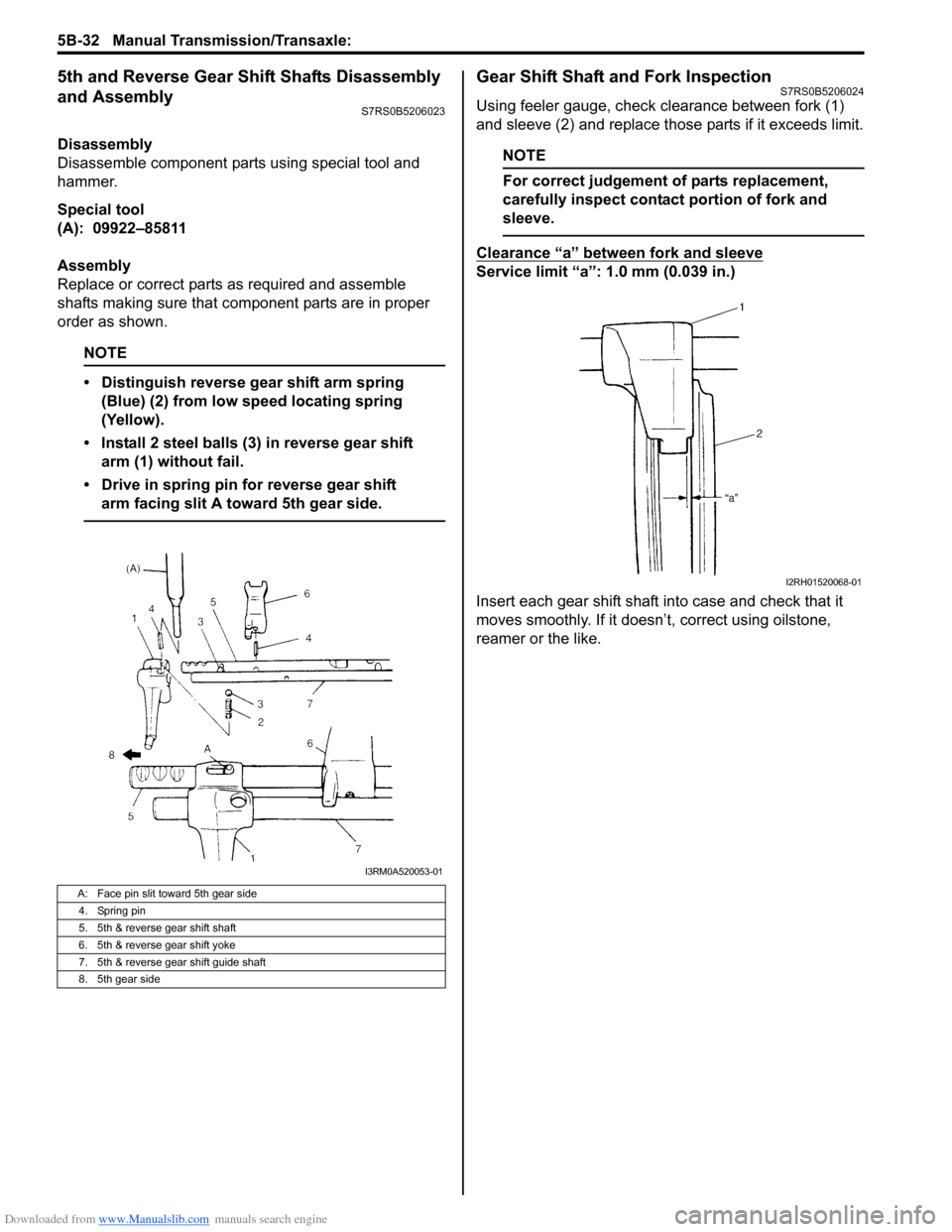
Disassemble component parts using special tool and
hammer.
Special tool
(A): 09922–85811
Assembly
Replace or correct parts as required and assemble
shafts making sure that component parts are in proper
order as shown.
NOTE
• Distinguish reverse gear shift arm spring (Blue) (2) from low speed locating spring
(Yellow).
• Install 2 steel balls (3) in reverse gear shift arm (1) without fail.
• Drive in spring pin for reverse gear shift arm facing slit A toward 5th gear side.
Gear Shift Shaft and Fork InspectionS7RS0B5206024
Using feeler gauge, check clearance between fork (1)
and sleeve (2) and replace those parts if it exceeds limit.
NOTE
For correct judgement of parts replacement,
carefully inspect contact portion of fork and
sleeve.
Clearance “a” between fork and sleeve
Service limit “a”: 1.0 mm (0.039 in.)
Insert each gear shift shaft into case and check that it
moves smoothly. If it doesn’t, correct using oilstone,
reamer or the like.
A: Face pin slit toward 5th gear side
4. Spring pin
5. 5th & reverse gear shift shaft
6. 5th & reverse gear shift yoke
7. 5th & reverse gear shift guide shaft
8. 5th gear side
I3RM0A520053-01
I2RH01520068-01
Page 847 of 1496
Downloaded from www.Manualslib.com manuals search engine Manual Transmission/Transaxle: 5B-33
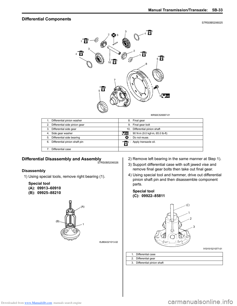
Differential ComponentsS7RS0B5206025
Differential Disassembly and AssemblyS7RS0B5206026
Disassembly1) Using special tools, remove right bearing (1).
Special tool
(A): 09913–60910
(B): 09925–88210 2) Remove left bearing in the same manner at Step 1).
3) Support differential case with soft jawed vise and
remove final gear bolts then take out final gear.
4) Using special tool and hammer, drive out differential pinion shaft pin and then disassemble component
parts.
Special tool
(C): 09922–85811
1. Differential pinion washer 8. Final gear
2. Differential side pinion gear 9. Final gear bolt
3. Differential side gear 10. Differential pinion shaft
4. Side gear washer : 90 N⋅m (9.0 kgf-m, 65.0 lb-ft)
5. Differential side bearing : Do not reuse.
6. Differential pinion shaft pin : Apply transaxle oil.
7. Differential case
I6RS0C520007-01
1(B)
(A)
I5JB0A321013-02
1. Differential case
2. Differential gear
3. Differential pinion shaft
IYSY01521077-01
Page 848 of 1496
Downloaded from www.Manualslib.com manuals search engine 5B-34 Manual Transmission/Transaxle:
Assembly
Judging from abnormality noted before disassembly and
what is found through visual check of component parts
after disassembly, prepare replacing parts and proceed
to reassembly. Make sure that all parts are clean.
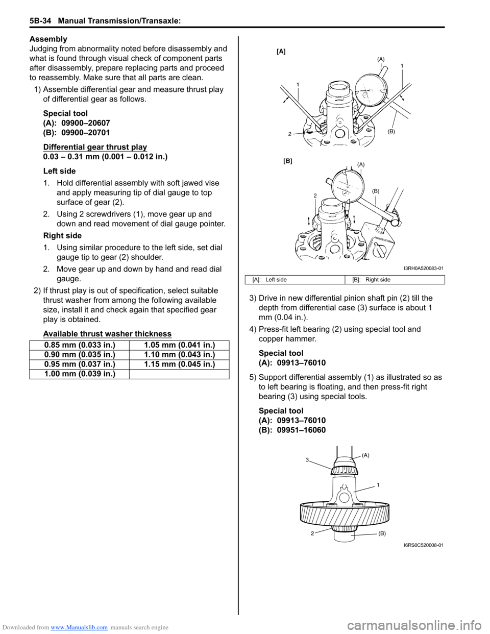
1) Assemble differential gear and measure thrust play
of differential gear as follows.
Special tool
(A): 09900–20607
(B): 09900–20701
Differential gear thrust play
0.03 – 0.31 mm (0.001 – 0.012 in.)
Left side
1. Hold differential assembly with soft jawed vise and apply measuring tip of dial gauge to top
surface of gear (2).
2. Using 2 screwdrivers (1), move gear up and down and read movement of dial gauge pointer.
Right side
1. Using similar procedure to the left side, set dial gauge tip to gear (2) shoulder.
2. Move gear up and down by hand and read dial gauge.
2) If thrust play is out of sp ecification, select suitable
thrust washer from among the following available
size, install it and check again that specified gear
play is obtained.
Available thrust washer thickness
3) Drive in new differential pinion shaft pin (2) till the depth from differential case (3) surface is about 1
mm (0.04 in.).
4) Press-fit left bearing (2) using special tool and copper hammer.
Special tool
(A): 09913–76010
5) Support differential assembly (1) as illustrated so as to left bearing is floating , and then press-fit right
bearing (3) using special tools.
Special tool
(A): 09913–76010
(B): 09951–16060
0.85 mm (0.033 in.) 1.05 mm (0.041 in.)
0.90 mm (0.035 in.) 1.10 mm (0.043 in.)
0.95 mm (0.037 in.) 1.15 mm (0.045 in.)
1.00 mm (0.039 in.)
[A]: Left side
[B]: Right side
I3RH0A520083-01
1
(A)
3
2 (B)
I6RS0C520008-01
Page 1039 of 1496
Downloaded from www.Manualslib.com manuals search engine Air Bag System: 8B-1
Restraint
Air Bag System
Precautions
Precautions on Service and Diagnosis of Air
Bag System
S7RS0B8200001
WARNING!
• If the air bag system and another vehicle system both need repair, SUZUKI
recommends that the air bag system be
repaired first, to help avoid unintended air
bag system activation.
• Do not modify the steering wheel, dashboard, both front seat or any other on
or around air bag system components.
Modifications can adversely affect air bag
system performance and lead to injury.
• Be sure to follow the procedures described in this section. Failure to follow
procedures could result in possible air bag
system activation, personal injury or
unneeded air bag system repairs.
• WARNING / CAUTION labels are attached on each
part of air bag system components (SDM, air bag
(inflator) modules and seat belt pretensioners). Be
sure to follow the instructions.
• Many of service procedures require disconnection of
“A/BAG” fuse and air bag (inflator) module(s) (driver,
passenger, side of both si des and curtain of both
sides) from initiator circuit to avoid an accidental
deployment.
• Do not apply power to the air bag system unless all components are connected or a diagnostic flow
requests it, as this will set a DTC.
• The “Air Bag Diagnostic S ystem Check” must be the
starting point of any air bag diagnostics. The “Air Bag
Diagnostic System Check” will verify proper “AIR
BAG” warning right operatio n and will lead you to the
correct flow to diagnose any air bag malfunctions.
Bypassing these procedures may result in extended
diagnostic time, incorrect diagnosis, and incorrect
parts replacements. • Never use air bag component parts from another
vehicle.
• If the vehicle will be exposed to temperatures over 93
° C (200 °F) (for example, during a paint baking
process), remove the air bag system components
beforehand to avoid component damage or
unintended system activation.
• When handling the air bag (inflator) modules (driver, passenger, side of both si des and curtain of both
sides), seat belt pretensio ners (driver and passenger),
SDM, forward-sensor or side-sensor, be careful not to
drop it or apply an impact to it. If an excessive impact
was applied (e.g., SDM, forward-sensor and side-
sensor are dropped, air bag (inflator) module is
dropped from a height of 90 cm (3 ft) or more, seat
belt pretensioner (retractor assembly) is dropped from
a height of 30 cm (1 ft) or more), never attempt
disassembly or repair but replace it with a new one.
• When using electric welding, be sure to disconnect air bag (inflator) module connectors (driver, passenger,
side of both sides and curtain of both sides) and seat
belt pretensioner connectors (driver and passenger)
respectively.
• When applying paint around the air bag system related parts, use care so that the harness or
connector will not be expo sed to the paint mist.
• Never expose air bag system component parts directly to hot air (drying or baking the vehicle after
painting) or flames.
WARNING!
When performing service on or around air
bag system components or air bag wiring,
follow the procedures listed in “Disabling Air
Bag System” to temporarily disable the air
bag system.
Failure to follow procedures could result in
possible air bag system activation, personal
injury or unneeded air bag system repairs.
Page 1040 of 1496
Downloaded from www.Manualslib.com manuals search engine 8B-2 Air Bag System:
Precautions on Handling and Storage of Air Bag
System Components
S7RS0B8200002
SDM
WARNING!
Never power up air bag system when SDM is
not rigidly attached to the vehicle. Otherwise,
personal injury may result.
CAUTION!
After detecting one time of such collision as
to meet deployment conditions, SDM must
not be used. Refer to “Air Bag Diagnostic
System Check” when checking SDM.
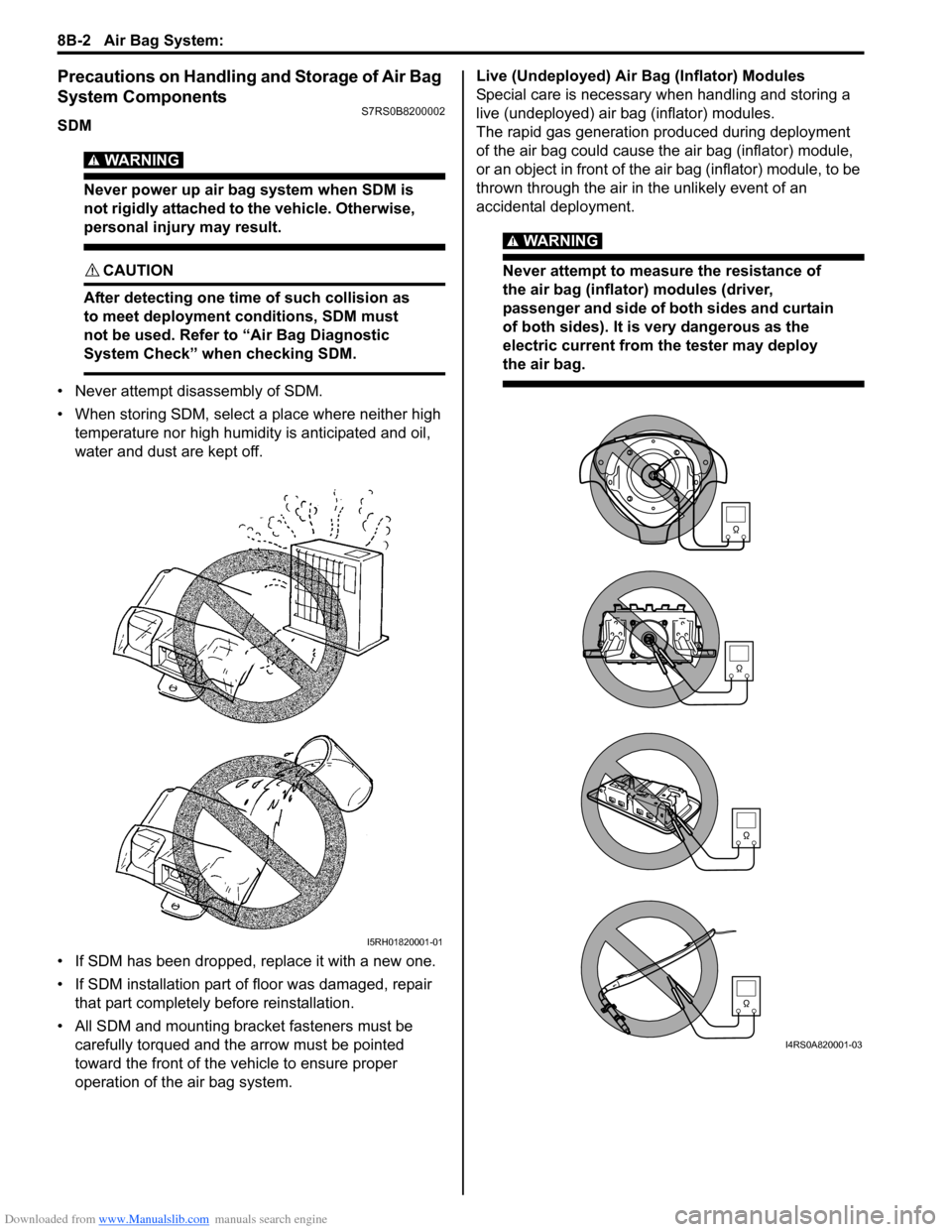
• Never attempt disassembly of SDM.
• When storing SDM, select a place where neither high temperature nor high humidity is anticipated and oil,
water and dust are kept off.
• If SDM has been dropped, replace it with a new one.
• If SDM installation part of floor was damaged, repair that part completely before reinstallation.
• All SDM and mounting bracket fasteners must be carefully torqued and the arrow must be pointed
toward the front of the vehicle to ensure proper
operation of the air bag system. Live (Undeployed) Air Bag (Inflator) Modules
Special care is necessary when handling and storing a
live (undeployed) air bag (inflator) modules.
The rapid gas generation produced during deployment
of the air bag could cause the air bag (inflator) module,
or an object in front of the air bag (inflator) module, to be
thrown through the air in the unlikely event of an
accidental deployment.
WARNING!
Never attempt to measure the resistance of
the air bag (inflator) modules (driver,
passenger and side of both sides and curtain
of both sides). It is
very dangerous as the
electric current from the tester may deploy
the air bag.
I5RH01820001-01
I4RS0A820001-03
Page 1041 of 1496
Downloaded from www.Manualslib.com manuals search engine Air Bag System: 8B-3
• Never attempt disassembly of the air bag (inflator) modules.
• If any abnormality is found, be sure to replace it with
new one as an assembly.
• When an abnormality is noted as existing in the live (undeployed) air bag (inflator) module, be sure to
deploy it before discarding it.
• When grease, cleaning agent, oil, water, etc., got on the air bag (inflator) modules (driver, passenger, side
of both sides and curtain of both sides), wipe it off
immediately with a dry cloth.
• If air bag (inflator) module was dropped from a height of 90 cm (3 ft) or more, it should be replaced with a
new one as an assembly.
WARNING!
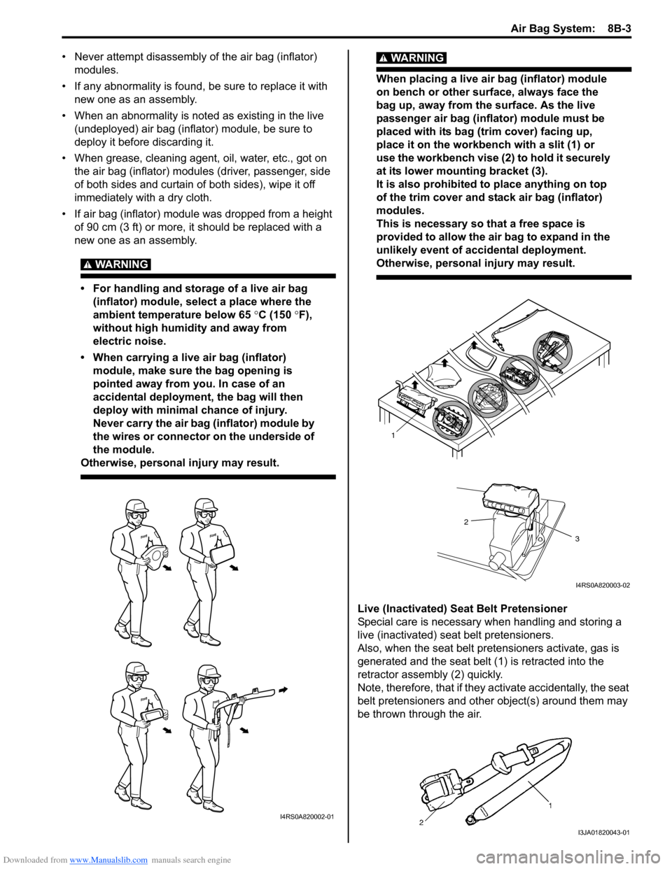
• For handling and storage of a live air bag (inflator) module, select a place where the
ambient temperature below 65 °C (150 ° F),
without high humidity and away from
electric noise.
• When carrying a live air bag (inflator) module, make sure the bag opening is
pointed away from you. In case of an
accidental deployment, the bag will then
deploy with minimal chance of injury.
Never carry the air bag (inflator) module by
the wires or connector on the underside of
the module.
Otherwise, personal injury may result.
WARNING!
When placing a live air bag (inflator) module
on bench or other surface, always face the
bag up, away from the surface. As the live
passenger air bag (inflator) module must be
placed with its bag (trim cover) facing up,
place it on the workbench with a slit (1) or
use the workbench vise (2) to hold it securely
at its lower mounting bracket (3).
It is also prohibited to place anything on top
of the trim cover and stack air bag (inflator)
modules.
This is necessary so that a free space is
provided to allow the air bag to expand in the
unlikely event of accidental deployment.
Otherwise, personal injury may result.
Live (Inactivated) Seat Belt Pretensioner
Special care is necessary when handling and storing a
live (inactivated) seat belt pretensioners.
Also, when the seat belt pretensioners activate, gas is
generated and the seat belt (1) is retracted into the
retractor assembly (2) quickly.
Note, therefore, that if they activate accidentally, the seat
belt pretensioners and other object(s) around them may
be thrown through the air.
I4RS0A820002-01
1
2
3
I4RS0A820003-02
I3JA01820043-01