2006 SUZUKI SWIFT disassembly
[x] Cancel search: disassemblyPage 741 of 1496
Downloaded from www.Manualslib.com manuals search engine Automatic Transmission/Transaxle: 5A-97
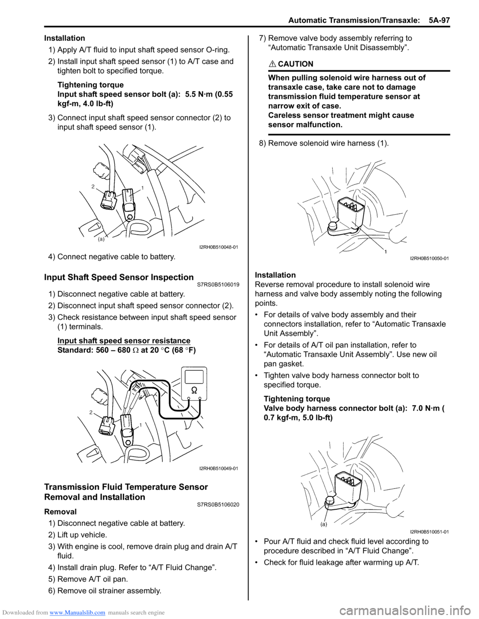
Installation1) Apply A/T fluid to input shaft speed sensor O-ring.
2) Install input shaft speed se nsor (1) to A/T case and
tighten bolt to specified torque.
Tightening torque
Input shaft speed sensor bolt (a): 5.5 N·m (0.55
kgf-m, 4.0 lb-ft)
3) Connect input shaft speed sensor connector (2) to input shaft speed sensor (1).
4) Connect negative cable to battery.
Input Shaft Speed Sensor InspectionS7RS0B5106019
1) Disconnect negative cable at battery.
2) Disconnect input shaft speed sensor connector (2).
3) Check resistance between input shaft speed sensor (1) terminals.
Input shaft speed sensor resistance
Standard: 560 – 680 Ω at 20 °C (68 °F)
Transmission Fluid Temperature Sensor
Removal and Installation
S7RS0B5106020
Removal
1) Disconnect negative cable at battery.
2) Lift up vehicle.
3) With engine is cool, remove drain plug and drain A/T fluid.
4) Install drain plug. Refer to “A/T Fluid Change”.
5) Remove A/T oil pan.
6) Remove oil stra iner assembly. 7) Remove valve body assembly referring to
“Automatic Transaxl e Unit Disassembly”.
CAUTION!
When pulling solenoid wire harness out of
transaxle case, take care not to damage
transmission fluid temperature sensor at
narrow exit of case.
Careless sensor treatment might cause
sensor malfunction.
8) Remove solenoid wire harness (1).
Installation
Reverse removal procedure to install solenoid wire
harness and valve body assembly noting the following
points.
• For details of valve body assembly and their connectors installation, refer to “Automatic Transaxle
Unit Assembly”.
• For details of A/T oil pa n installation, refer to
“Automatic Transaxle Unit Assembly”. Use new oil
pan gasket.
• Tighten valve body harness connector bolt to specified torque.
Tightening torque
Valve body harness connector bolt (a): 7.0 N·m (
0.7 kgf-m, 5.0 lb-ft)
• Pour A/T fluid and check fluid level according to procedure described in “A/T Fluid Change”.
• Check for fluid leakage after warming up A/T.
I2RH0B510048-01
I2RH0B510049-01
I2RH0B510050-01
I2RH0B510051-01
Page 745 of 1496
Downloaded from www.Manualslib.com manuals search engine Automatic Transmission/Transaxle: 5A-101
Pressure Control Solenoid Valves (Pressure
Control Solenoid and TCC Pressure Control
Solenoid) Removal and Installation
S7RS0B5106024
Removal1) Disconnect negative cable at battery.
2) Lift up vehicle.
3) Remove drain plug and drain A/T fluid.
4) Install drain plug.
Tightening torque
A/T fluid drain plug: 17 N·m (1.7 kgf-m, 12.5 lb-ft)
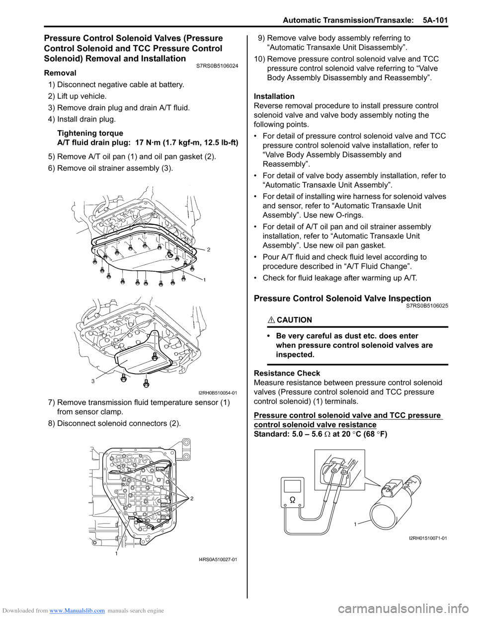
5) Remove A/T oil pan (1) and oil pan gasket (2).
6) Remove oil strain er assembly (3).
7) Remove transmission fluid temperature sensor (1) from sensor clamp.
8) Disconnect solenoid connectors (2). 9) Remove valve body assembly referring to
“Automatic Transaxl e Unit Disassembly”.
10) Remove pressure control solenoid valve and TCC pressure control solenoid valve referring to “Valve
Body Assembly Disassembly and Reassembly”.
Installation
Reverse removal procedure to install pressure control
solenoid valve and valve body assembly noting the
following points.
• For detail of pressure control solenoid valve and TCC pressure control solenoid va lve installation, refer to
“Valve Body Assembly Disassembly and
Reassembly”.
• For detail of valve body asse mbly installation, refer to
“Automatic Transaxle Unit Assembly”.
• For detail of installing wire harness for solenoid valves and sensor, refer to “Automatic Transaxle Unit
Assembly”. Use new O-rings.
• For detail of A/T oil pan and oil strainer assembly
installation, refer to “A utomatic Transaxle Unit
Assembly”. Use new oil pan gasket.
• Pour A/T fluid and check fluid level according to procedure described in “A/T Fluid Change”.
• Check for fluid leakage after warming up A/T.
Pressure Control Solenoid Valve InspectionS7RS0B5106025
CAUTION!
• Be very careful as dust etc. does enter when pressure control solenoid valves are
inspected.
Resistance Check
Measure resistance between pressure control solenoid
valves (Pressure control solenoid and TCC pressure
control solenoid) (1) terminals.
Pressure control solenoid valve and TCC pressure
control solenoid valve resistance
Standard: 5.0 – 5.6 Ω at 20 °C (68 °F)
I2RH0B510054-01
1 2I4RS0A510027-01
1
I2RH01510071-01
Page 754 of 1496
Downloaded from www.Manualslib.com manuals search engine 5A-110 Automatic Transmission/Transaxle:
Automatic Transaxle Unit DisassemblyS7RS0B5106033
CAUTION!
• Thoroughly clean transaxle exterior before overhauling it.
• Keep working table, tools and hands clean while overhauling.
• Use special care to handle aluminum parts so as not to damage them.
• Do not expose removed parts to dust. Keep them always clean.
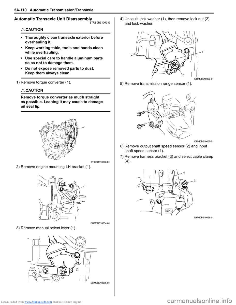
1) Remove torque converter (1).
CAUTION!
Remove torque converte r as much straight
as possible. Leaning it may cause to damage
oil seal lip.
2) Remove engine mounting LH bracket (1).
3) Remove manual select lever (1). 4) Uncaulk lock washer (1),
then remove lock nut (2)
and lock washer.
5) Remove transmission range sensor (1).
6) Remove output shaft speed sensor (2) and input shaft speed sensor (1).
7) Remove harness bracket (3) and select cable clamp (4).
I2RH0B510078-01
I3RM0B510054-01
1
I3RM0B510055-01
1
2
I3RM0B510056-01
I3RM0B510057-01
I3RM0B510058-01
Page 766 of 1496
Downloaded from www.Manualslib.com manuals search engine 5A-122 Automatic Transmission/Transaxle:
Oil Pump Assembly Disassembly and
Reassembly
S7RS0B5106035
Disassembly1) Remove O-ring from pump body.
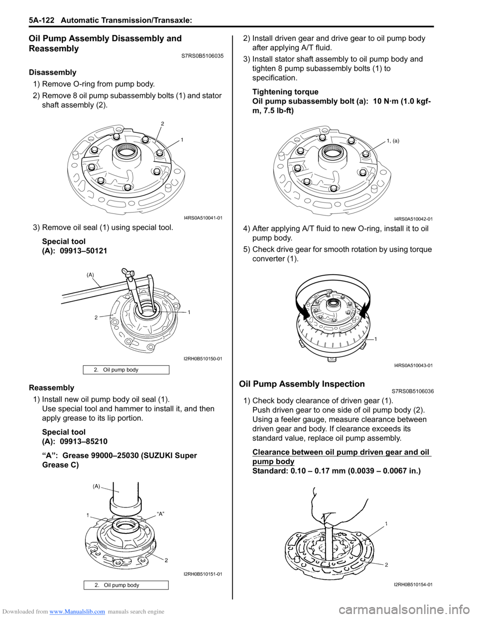
2) Remove 8 oil pump subassembly bolts (1) and stator shaft assembly (2).
3) Remove oil seal (1) using special tool. Special tool
(A): 09913–50121
Reassembly 1) Install new oil pump body oil seal (1). Use special tool and hammer to install it, and then
apply grease to its lip portion.
Special tool
(A): 09913–85210
“A”: Grease 99000–25030 (SUZUKI Super
Grease C) 2) Install driven gear and drive gear to oil pump body
after applying A/T fluid.
3) Install stator shaft assembly to oil pump body and tighten 8 pump subassembly bolts (1) to
specification.
Tightening torque
Oil pump subassembly bolt (a): 10 N·m (1.0 kgf-
m, 7.5 lb-ft)
4) After applying A/T fluid to new O-ring, install it to oil pump body.
5) Check drive gear for smooth rotation by using torque converter (1).
Oil Pump Assembly InspectionS7RS0B5106036
1) Check body clearance of driven gear (1).Push driven gear to one side of oil pump body (2).
Using a feeler gauge, m easure clearance between
driven gear and body. If clearance exceeds its
standard value, replace oil pump assembly.
Clearance between oil pump driven gear and oil
pump body
Standard: 0.10 – 0.17 mm (0.0039 – 0.0067 in.)
2. Oil pump body
2. Oil pump body
2 1
I4RS0A510041-01
I2RH0B510150-01
I2RH0B510151-01
1, (a)
I4RS0A510042-01
1
I4RS0A510043-01
I2RH0B510154-01
Page 769 of 1496

Downloaded from www.Manualslib.com manuals search engine Automatic Transmission/Transaxle: 5A-125
Direct Clutch Assembly Disassembly and
Reassembly
S7RS0B5106039
Disassembly1) Remove plate snap ring (1) then remove direct clutch retaining plate, discs and separator plates.
2) Using special tool and hydraulic press, remove shaft snap ring (1).
Special tool
(A): 09926–98310
CAUTION!
Do not press direct clutch return spring
subassembly in over 0.7 mm (0.027 in.).
Excessive compression may cause damage
to direct clutch return spring subassembly
and/or piston.
3) Remove direct clutch re turn spring assembly (2).
4) Using a finger to block oil hole (1), apply compressed air (400 – 800 kPa, 4 – 8 kg/cm
2, 57 –
113 psi) to opposite hole, which will assist in removal
of the clutch piston. 5) Remove outer O-ring (1).
6) Remove inner O-ring (2).
7) Remove input shaft seal rings (1).
I2RH0B510162-01
I2RH0B510163-01
I2RH0B510164-01
2. Direct clutch piston
1. Input shaft subassembly
I2RH0B510165-01
I2RH0B510166-01
I2RH0B510167-01
Page 770 of 1496

Downloaded from www.Manualslib.com manuals search engine 5A-126 Automatic Transmission/Transaxle:
Reassembly
Reverse disassembly procedure for assembly, noting the
following points.
• Use new seal ring and O-ring. Apply A/T fluid before installation.
• Do not damage direct clutch return spring subassembly (1) and piston by pressing in direct
clutch return spring subassembly passing through its
original installing position over 0.7 mm (0.027 in.).
Special tool
(A): 09926–98310
• Apply A/T fluid to direct cl utch separator plates (4),
discs (3) and retaining plate (2).
• Install direct clutch separator plates (4), discs (3), retaining plate (2) and snap ring (1) to input shaft
subassembly.
• Install plate snap ring so that its both ends would be positioned in correct locations as shown in figure. • After assembly, measure direct clutch piston stroke.
Special tool
(A): 09900–20607
(B): 09900–20701
Direct clutch piston stroke
0.4 – 0.7 mm (0.016 – 0.027 in.)
When piston stroke is out of specification, select direct
clutch retaining plate with suitable thickness from
among the following table and replace it.
Available direct clutch retaining plate thickness
I2RH0B510168-01
I2RH0B510169-01
[A]: Correct [B]: Incorrect
ThicknessIdentification mark
3.0 mm (0.118 in.) 1
3.2 mm (0.126 in.) 2
3.4 mm (0.134 in.) 3
2.8 mm (0.110 in.) 4
1. Direct clutch assembly 3. Oil hole
2. Oil pump assembly
I2RH0B510170-01
I2RH0B510171-01
Page 773 of 1496
Downloaded from www.Manualslib.com manuals search engine Automatic Transmission/Transaxle: 5A-129
Forward and Reverse Clutch Assembly
Preliminary Check
S7RS0B5106042
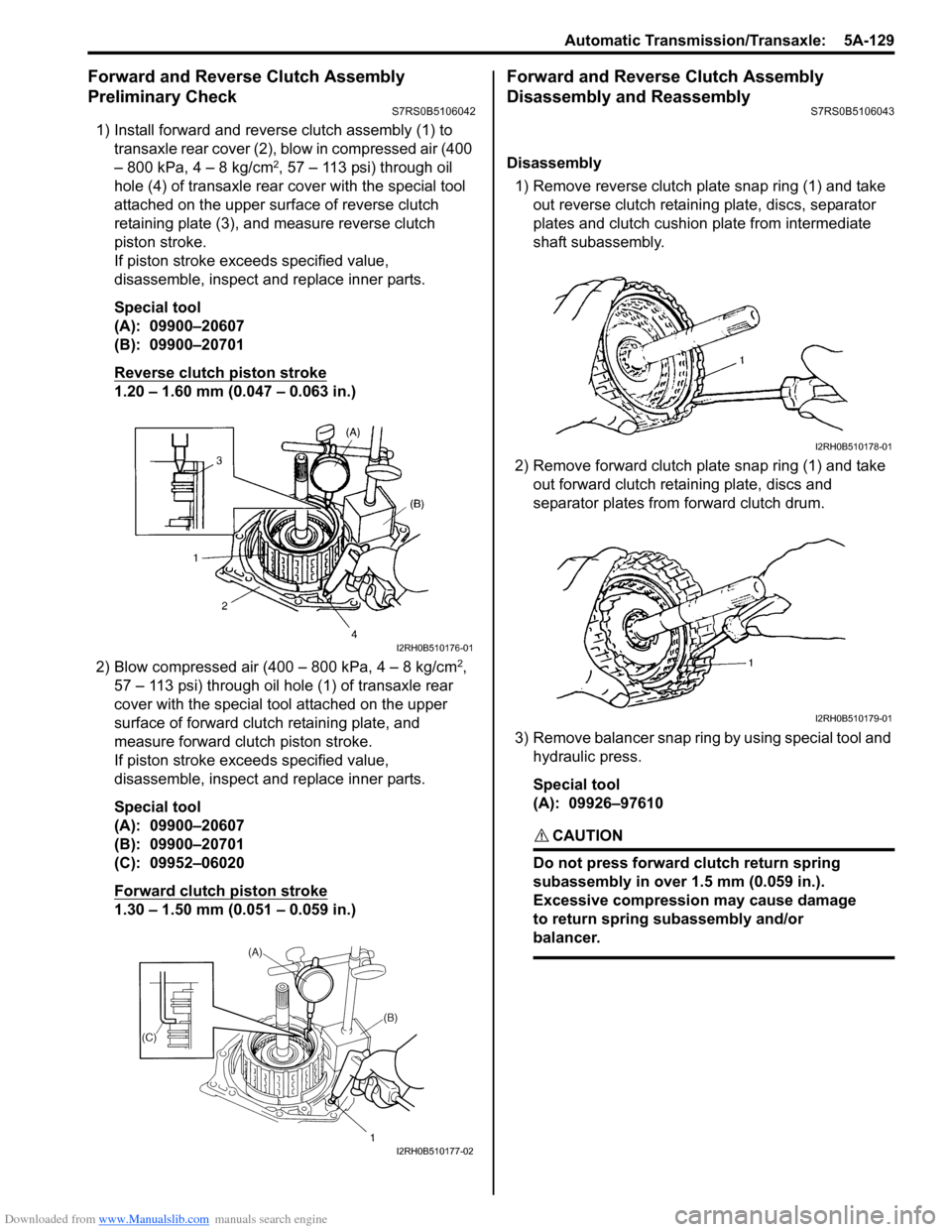
1) Install forward and reverse clutch assembly (1) to
transaxle rear cover (2), blow in compressed air (400
– 800 kPa, 4 – 8 kg/cm
2, 57 – 113 psi) through oil
hole (4) of transaxle rear cover with the special tool
attached on the upper surf ace of reverse clutch
retaining plate (3), and measure reverse clutch
piston stroke.
If piston stroke exce eds specified value,
disassemble, inspect and replace inner parts.
Special tool
(A): 09900–20607
(B): 09900–20701
Reverse clutch piston stroke
1.20 – 1.60 mm (0.047 – 0.063 in.)
2) Blow compressed air (400 – 800 kPa, 4 – 8 kg/cm
2,
57 – 113 psi) through oil hole (1) of transaxle rear
cover with the special tool attached on the upper
surface of forward clutch retaining plate, and
measure forward clutch piston stroke.
If piston stroke exce eds specified value,
disassemble, inspect and replace inner parts.
Special tool
(A): 09900–20607
(B): 09900–20701
(C): 09952–06020
Forward clutch piston stroke
1.30 – 1.50 mm (0.051 – 0.059 in.)
Forward and Reverse Clutch Assembly
Disassembly and Reassembly
S7RS0B5106043
Disassembly
1) Remove reverse clutch plate snap ring (1) and take out reverse clutch retaini ng plate, discs, separator
plates and clutch cushion plate from intermediate
shaft subassembly.
2) Remove forward clutch plate snap ring (1) and take out forward clutch retaining plate, discs and
separator plates from forward clutch drum.
3) Remove balancer snap ring by using special tool and hydraulic press.
Special tool
(A): 09926–97610
CAUTION!
Do not press forward clutch return spring
subassembly in over 1.5 mm (0.059 in.).
Excessive compression may cause damage
to return spring subassembly and/or
balancer.
I2RH0B510176-01
I2RH0B510177-02
I2RH0B510178-01
I2RH0B510179-01
Page 775 of 1496

Downloaded from www.Manualslib.com manuals search engine Automatic Transmission/Transaxle: 5A-131
Reassembly
Reverse disassembly procedure for assembly, noting the
following points.
• Before assembling, apply automatic transaxle fluid to component parts.
• Replace O-rings and seal ring with new ones.
• Do not damage forward clutch return spring subassembly and balancer (1) by pressing forward
clutch return spring subassembly passing through its
original installing position over 1.5 mm (0.059 in.).
Special tool
(A): 09926–97610
• Apply A/T fluid to forward clutch separator plates (1), discs (2) and retaining plate (3).
• Install forward clutch separator plates (1), discs (2) and retaining plate (3), then snap ring (4) to forward
clutch drum. • Install forward clutch plate snap ring so that its both
ends would be positioned in correct locations as
shown in figure.
I2RH0B510180-01
4
1
2 3
I5RW0C510062-01
[A]: Correct
[B]: Incorrect
I2RH0B510188-01