2006 SUZUKI SWIFT throt
[x] Cancel search: throtPage 153 of 1496

Downloaded from www.Manualslib.com manuals search engine Engine General Information and Diagnosis: 1A-103
NOTE
When DTC P0123 and P0223 are indicated together, it is possible that “RED” wire shorted to power
circuit and/or “BLK” wire open.
DTC Confirmation Procedure
1) With ignition switch turned OFF, connect scan tool.
2) Turn ON ignition switch and clear DTC using scan tool.
3) Keep the accelerator pedal at idle position for 2 seconds.
4) Keep the accelerator pedal at fully depressed position for 2 seconds.
5) Repeat Step 3) and 4) for 3 times.
6) Check DTC.
DTC Troubleshooting
NOTE
• When measuring circuit voltage, resistance and/ or pulse signal at ECM connector, connect the
special tool to ECM and/or the ECM connectors re ferring to “Inspection of ECM and Its Circuits”.
• Upon completion of inspection and repair work, perform “DTC Confirmation Procedure” and confirm that the trouble has been corrected.
Step Action YesNo
1 Was “Engine and Emission Control System Check”
performed? Go to Step 2.
Go to “Engine and
Emission Control
System Check”.
2 TP sensor and its circuit check
1) Connect scan tool to DLC with ignition switch turned
OFF.
2) Turn ON ignition switch, check “TP Sensor 2 Volt” displayed on scan tool when accelerator pedal is idle
position and fully depressed.
Is displayed TP sensor value as described voltage in “Scan
To o l D a t a ” ? Intermittent trouble.
Check for intermittent
referring to “Intermittent
and Poor Connection
Inspection in Section
00”.
Go to Step 3.
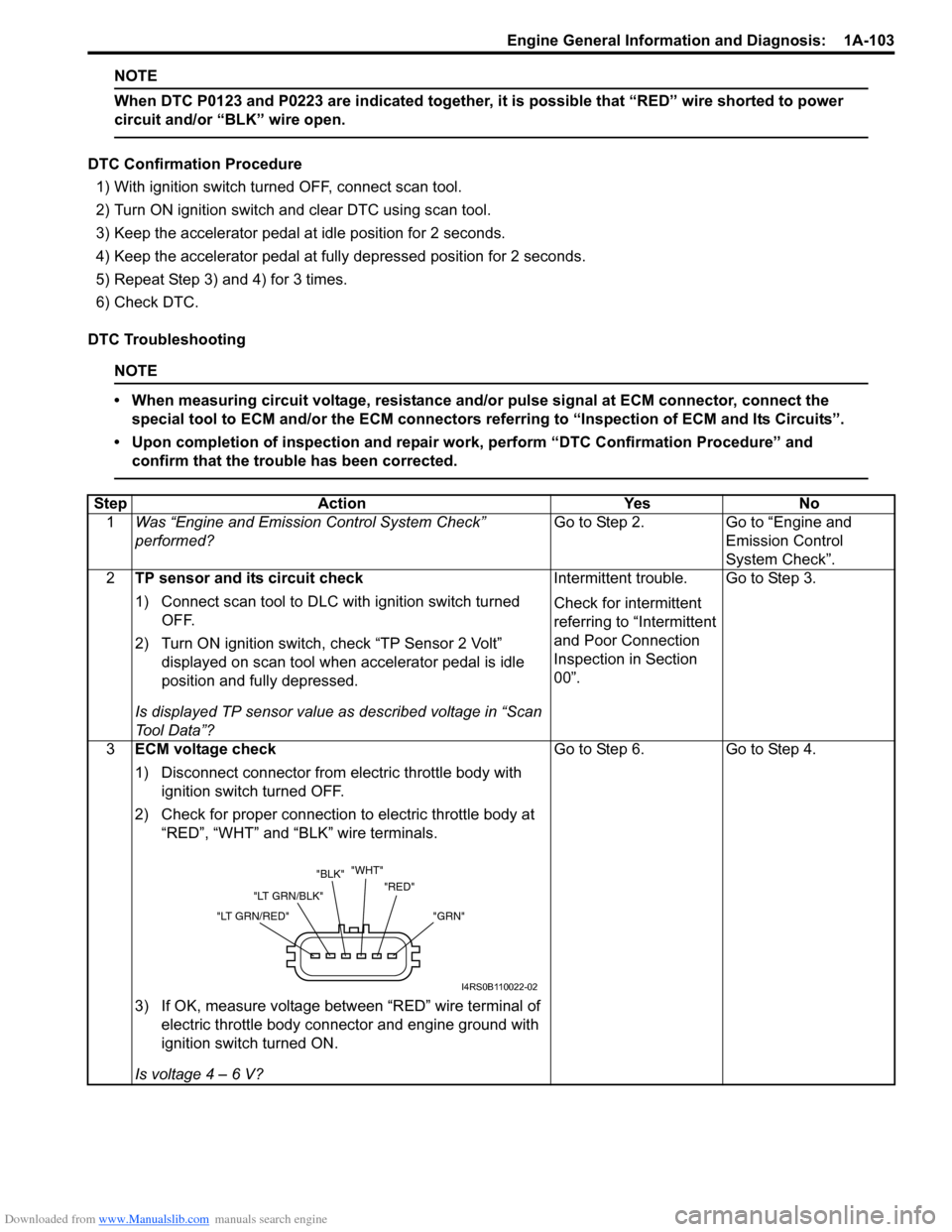
3 ECM voltage check
1) Disconnect connector from electric throttle body with
ignition switch turned OFF.
2) Check for proper connection to electric throttle body at “RED”, “WHT” and “BLK” wire terminals.
3) If OK, measure voltage between “RED” wire terminal of electric throttle body connector and engine ground with
ignition switch turned ON.
Is voltage 4 – 6 V? Go to Step 6.
Go to Step 4.
"GRN"
"RED"
"WHT"
"BLK"
"LT GRN/BLK"
"LT GRN/RED"
I4RS0B110022-02
Page 154 of 1496

Downloaded from www.Manualslib.com manuals search engine 1A-104 Engine General Information and Diagnosis:
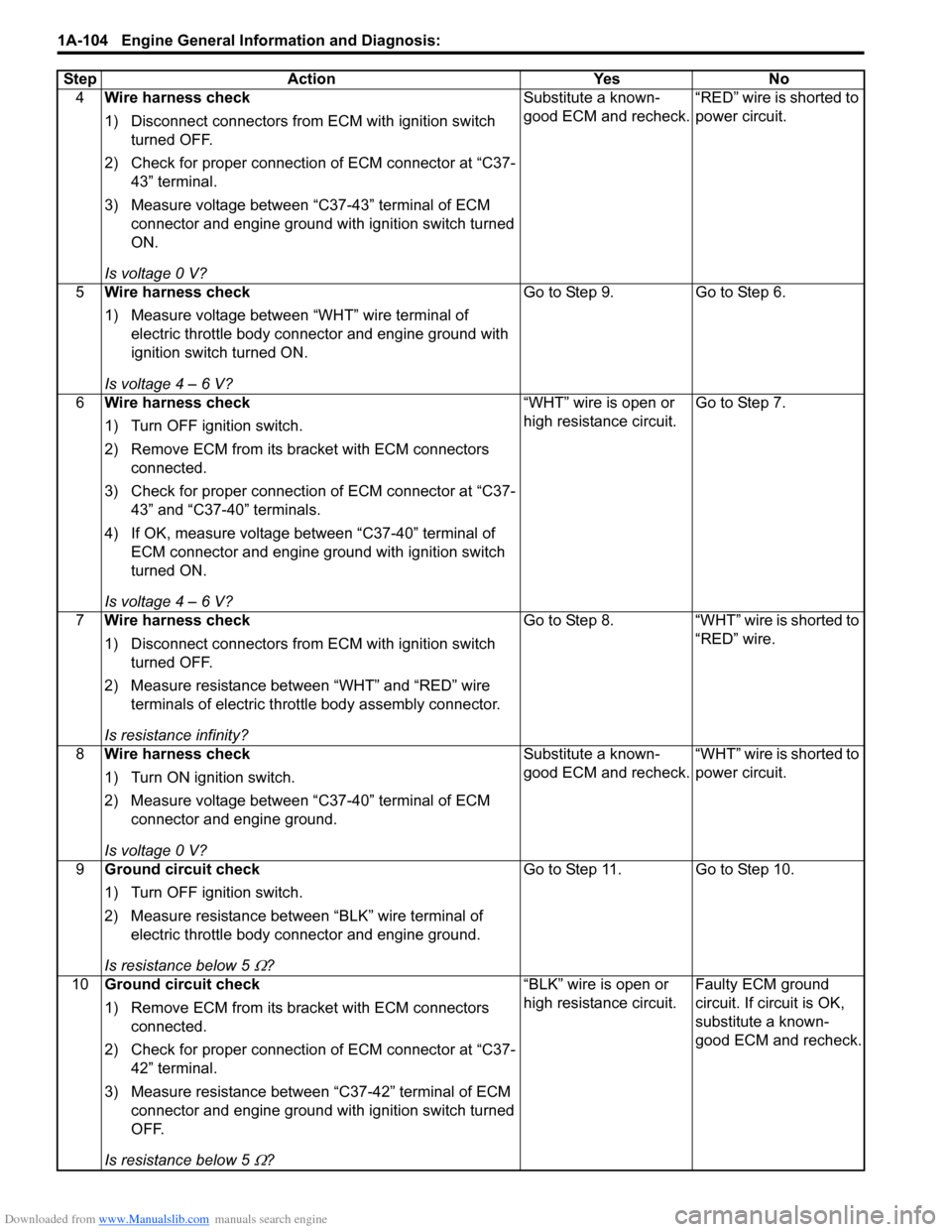
4Wire harness check
1) Disconnect connectors from ECM with ignition switch
turned OFF.
2) Check for proper connection of ECM connector at “C37- 43” terminal.
3) Measure voltage between “C37-43” terminal of ECM connector and engine ground with ignition switch turned
ON.
Is voltage 0 V? Substitute a known-
good ECM and recheck.
“RED” wire is shorted to
power circuit.
5 Wire harness check
1) Measure voltage between “WHT” wire terminal of
electric throttle body connector and engine ground with
ignition switch turned ON.
Is voltage 4 – 6 V? Go to Step 9.
Go to Step 6.
6 Wire harness check
1) Turn OFF ignition switch.
2) Remove ECM from its br acket with ECM connectors
connected.
3) Check for proper connection of ECM connector at “C37- 43” and “C37-40” terminals.
4) If OK, measure voltage between “C37-40” terminal of ECM connector and engine ground with ignition switch
turned ON.
Is voltage 4 – 6 V? “WHT” wire is open or
high resistance circuit.
Go to Step 7.
7 Wire harness check
1) Disconnect connectors from ECM with ignition switch
turned OFF.
2) Measure resistance between “WHT” and “RED” wire terminals of electric thrott le body assembly connector.
Is resistance infinity? Go to Step 8.
“WHT” wire is shorted to
“RED” wire.
8 Wire harness check
1) Turn ON ignition switch.
2) Measure voltage between “C37-40” terminal of ECM
connector and engine ground.
Is voltage 0 V? Substitute a known-
good ECM and recheck.
“WHT” wire is shorted to
power circuit.
9 Ground circuit check
1) Turn OFF ignition switch.
2) Measure resistance between “BLK” wire terminal of
electric throttle body connector and engine ground.
Is resistance below 5
Ω? Go to Step 11. Go to Step 10.
10 Ground circuit check
1) Remove ECM from its br acket with ECM connectors
connected.
2) Check for proper connection of ECM connector at “C37- 42” terminal.
3) Measure resistance between “C37-42” terminal of ECM connector and engine ground with ignition switch turned
OFF.
Is resistance below 5
Ω? “BLK” wire is open or
high resistance circuit.
Faulty ECM ground
circuit. If circuit is OK,
substitute a known-
good ECM and recheck.
Step Action Yes No
Page 155 of 1496

Downloaded from www.Manualslib.com manuals search engine Engine General Information and Diagnosis: 1A-105
DTC P0300 / P0301 / P0302 / P0303 / P0304: Random / Multiple Cylinder Misfire Detected / Cylinder 1
/ Cylinder 2 / Cylinder 3 / Cylinder 4 Misfire Detected
S7RS0B1104039
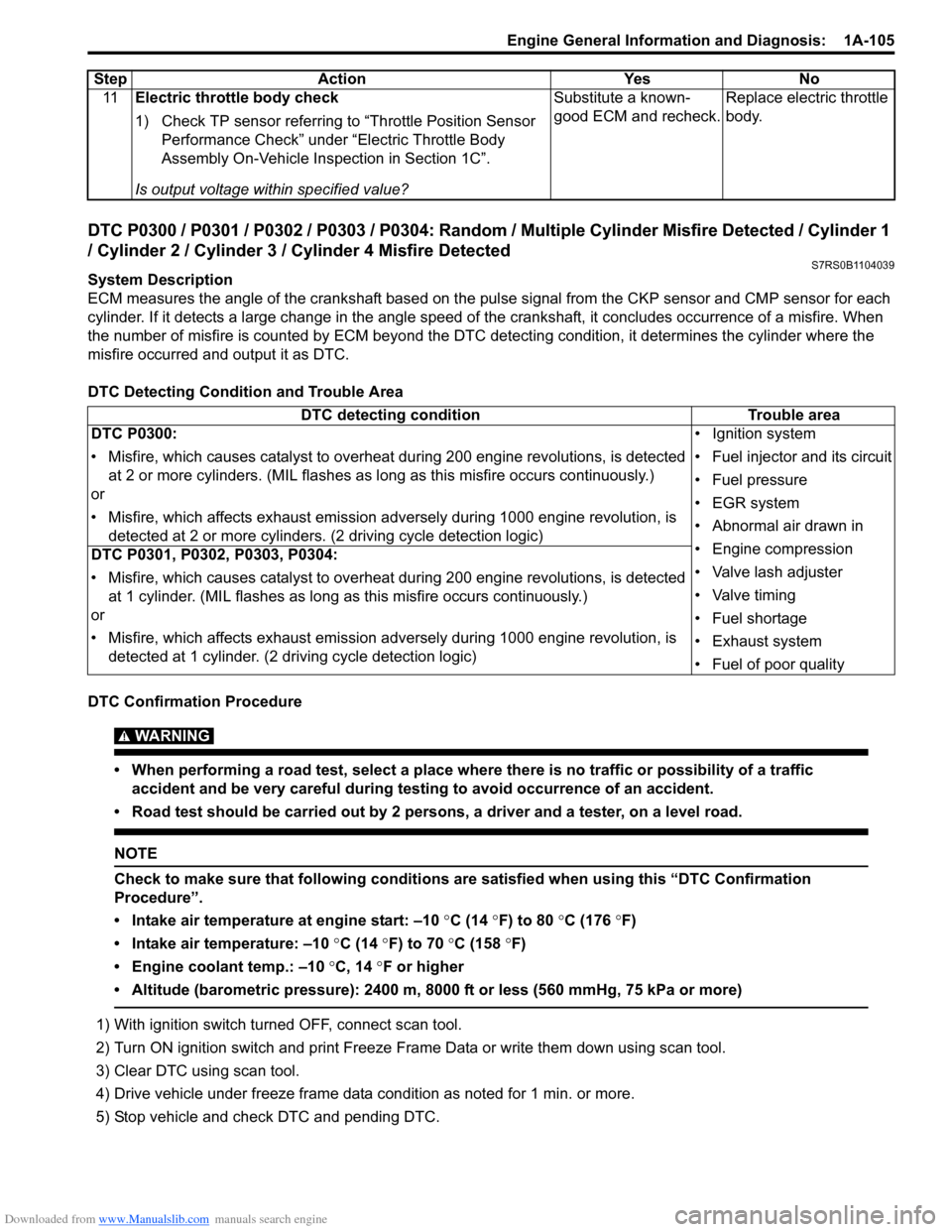
System Description
ECM measures the angle of the crankshaft based on the pulse signal from the CKP sensor and CMP sensor for each
cylinder. If it detects a large change in the angle speed of the crankshaft, it concludes occurrence of a misfire. When
the number of misfire is counted by ECM beyond the DTC de tecting condition, it determines the cylinder where the
misfire occurred and output it as DTC.
DTC Detecting Condition and Trouble Area
DTC Confirmation Procedure
WARNING!
• When performing a road test, select a place where there is no traffic or possibility of a traffic accident and be very careful during testing to avoid occurrence of an accident.
• Road test should be carried out by 2 persons, a driver and a tester, on a level road.
NOTE
Check to make sure that following conditions ar e satisfied when using this “DTC Confirmation
Procedure”.
• Intake air temperature at engine start: –10 °C (14 ° F) to 80 °C (176 °F)
• Intake air temperature: –10 °C (14 °F) to 70 °C (158 °F)
• Engine coolant temp.: –10 °C, 14 °F or higher
• Altitude (barometric pressure): 2400 m, 8000 ft or less (560 mmHg, 75 kPa or more)
1) With ignition switch turned OFF, connect scan tool.
2) Turn ON ignition switch and print Freeze Frame Data or write them down using scan tool.
3) Clear DTC using scan tool.
4) Drive vehicle under freeze frame data condition as noted for 1 min. or more.
5) Stop vehicle and check DTC and pending DTC. 11
Electric throttle body check
1) Check TP sensor referring to “Throttle Position Sensor
Performance Check” under “Electric Throttle Body
Assembly On-Vehicle Inspection in Section 1C”.
Is output voltage within specified value? Substitute a known-
good ECM and recheck.
Replace electric throttle
body.
Step Action Yes No
DTC detecting condition
Trouble area
DTC P0300:
• Misfire, which causes catalyst to overheat during 200 engine revolutions, is detected at 2 or more cylinders. (MIL flashes as lo ng as this misfire occurs continuously.)
or
• Misfire, which affects exhaust emission adv ersely during 1000 engine revolution, is
detected at 2 or more cylinders. (2 driving cycle detection logic) • Ignition system
• Fuel injector and its circuit
• Fuel pressure
• EGR system
• Abnormal air drawn in
• Engine compression
• Valve lash adjuster
• Valve timing
• Fuel shortage
• Exhaust system
• Fuel of poor quality
DTC P0301, P0302, P0303, P0304:
• Misfire, which causes catalyst to overheat during 200 engine revolutions, is detected
at 1 cylinder. (MIL flashes as long as this misfire occurs continuously.)
or
• Misfire, which affects exhaust emission adv ersely during 1000 engine revolution, is
detected at 1 cylinder. (2 driving cycle detection logic)
Page 202 of 1496

Downloaded from www.Manualslib.com manuals search engine 1A-152 Engine General Information and Diagnosis:
DTC P2101: Throttle Actuator Control Motor Circuit Range / PerformanceS7RS0B1104067
Wiring Diagram
DTC Detecting Condition and Trouble Area
DTC Confirmation Procedure1) With ignition switch turned OFF, connect scan tool.
2) Turn ON ignition switch and clear DTC using scan tool.
3) Keep the accelerator pedal at idle position for 2 seconds.
4) Keep the accelerator pedal at fully depressed position for 2 seconds.
5) Repeat Step 3) and 4) for 3 times.
6) Check DTC.
E23 C37
34
1819
567
1011
17
20
47 46
495051
2122
52 16
25 9
24
14
29
55
57 54 53
59
60 58 2
262728
15
30
56 4832 31
34353637
40
42 39 38
44
45 43 41 331
1213
238
34
1819
567
1011
17
20
47 46
495051
2122
52 16
25 9
24
14
29
55
57 54 53
59
60 58 2
262728
15
30
56 4832 31
34353637
40
42 39 38
44
45 43 41 331
1213
238
12V
5VBLK/REDBLK/RED
BLK/YEL
12BLK/YEL
BLK/YEL
BRN/WHT
E23-1
E23-60
C37-58
C37-15 C37-30
BLK/ORN
BLKBLKE23-31 BLK
BLK/RED
BLU/ORN
RED/YELYEL/BLU
LT GRN/RED
LT GRN/BLK
RED
GRN
WHT
BLK
E23-16
E23-45
E23-32
C37-45
C37-44
C37-41C37-42
C37-40
C37-54
C37-43
1-1
1-2
1-3 3
4
5
8 67
10
9
E23-29 GRNBLK/WHTWHT
BLK/RED
I6RS0C110015-01
1. Electric throttle body assembly
3. ECM 8. “IG ACC” fuse
1-1. Throttle actuator 4. Main relay9. “IG COIL” fuse
1-2. TP sensor (main) 5. Individual circuit fuse box No.1 10. Ignition switch
1-3. TP sensor (sub) 6. “TH MOT” fuse
2. Throttle actuator control relay 7. “FI” fuse
DTC detecting condition Trouble area
Monitor signal of throttle actu ator output (duty output) is
inconsistent with throttle actuator control command.
(1 driving detection logic) • Throttle actuator circuit
• Electric throttle body
•ECM
Page 203 of 1496

Downloaded from www.Manualslib.com manuals search engine Engine General Information and Diagnosis: 1A-153
DTC Troubleshooting
NOTE
• When measuring circuit voltage, resistance and/or pulse signal at ECM connector, connect the
special tool to ECM and/or the ECM connectors re ferring to “Inspection of ECM and Its Circuits”.
• Upon completion of inspection and repair work, perform “DTC Confirmation Procedure” and confirm that the trouble has been corrected.
Step Action YesNo
1 Was “Engine and Emission Control System Check”
performed? Go to Step 2.
Go to “Engine and
Emission Control
System Check”.
2 Throttle actuator circuit check
1) Disconnect connectors from electric throttle body and
ECM with ignition switch turned OFF.
2) Check for proper connection of electric throttle body and ECM connectors at “LT GRN/RED” wire, “LT GRN/BLK”
wire. “C37-45” and “C37-44” terminals.
3) Turn ON ignition switch.
4) Measure voltage between “LT GRN/RED” wire terminal of electric throttle body connector and engine ground,
between “LT GRN/BLK” wire terminal of electric throttle
body connector and engine ground.
Is voltage 0 V? Go to Step 3.
“LT GRN/RED” wire
and/or “LT GRN/BLK”
wire is shorted to power
circuit.
3 Throttle actuator circuit check
1) Turn OFF ignition switch.
2) Measure resistance between “LT GRN/RED” wire
terminal of electric throttle body connector and engine
ground, between “LT GRN/BLK” wire terminal of electric
throttle body connector and engine ground.
Is resistance infinity? Go to Step 4.
“LT GRN/RED” wire
and/or “LT GRN/BLK”
wire is shorted to
ground circuit.
4 Throttle actuator circuit check
1) Check throttle actuator refe rring to “Throttle Actuator
Performance Check” under “Electric Throttle Body
Assembly On-Vehicle Inspection in Section 1C”.
Is check result satisfactory? Substitute a known-
good ECM and recheck.
Replace electric throttle
body
"GRN"
"RED"
"WHT"
"BLK"
"LT GRN/BLK"
"LT GRN/RED"
I4RS0B110022-02
Page 204 of 1496

Downloaded from www.Manualslib.com manuals search engine 1A-154 Engine General Information and Diagnosis:
DTC P2102: Throttle Actuator Control Motor Circuit LowS7RS0B1104068
Wiring Diagram
Refer to “DTC P2101: Throttle Actuator Control Motor Circuit Range / Performance”.
DTC Detecting Condition and Trouble Area
DTC Confirmation Procedure 1) With ignition switch turned OFF, connect scan tool.
2) Turn ON ignition switch and clear DTC using scan tool.
3) Start engine and run it for 1 min. or more.
4) Check DTC.
DTC Troubleshooting
NOTE
• When measuring circuit voltage, resistance and/ or pulse signal at ECM connector, connect the
special tool to ECM and/or the ECM connectors re ferring to “Inspection of ECM and Its Circuits”.
• Upon completion of inspection and repair work, perform “DTC Confirmation Procedure” and confirm that the trouble has been corrected.
DTC detecting condition Trouble area
Power supply voltage of throttle actuator control circuit is
less than 5 V for specified time even if throttle actuator
control relay is turned on.
(1 driving detection logic) • Throttle actuator control relay circuit
• Throttle actuator control relay
•ECM
Step
Action YesNo
1 Was “Engine and Emission Control System Check”
performed? Go to Step 2.
Go to “Engine and
Emission Control
System Check”.
2 Throttle actuator cont rol relay circuit check
1) Remove ECM from its br acket with ECM connectors
connected.
2) Check for proper connection of ECM connector at “E23- 45” and “E23-32” terminals.
3) Turn ON ignition switch.
4) Measure voltage between “E23-32” terminal of ECM connector and engine ground.
Is voltage 10 – 14 V? Intermittent trouble.
Check for intermittent
referring to “Intermittent
and Poor Connection
Inspection in Section
00”.
Go to Step 3.
3 Is “TH MOT” fuse in god condition? Go to Step 4Replace fuse and check
for short in circuits
connected to this fuse.
4 Throttle actuator cont rol relay circuit check
1) Remove throttle actuator co ntrol relay from individual
circuit fuse box No.1 with ignition switch turned OFF.
2) Check for proper connection to throttle actuator control relay at “BLK/RED”, “YEL/BLU”, “BLU/ORN” and “RED/
YEL” wire terminals.
3) Measure voltage between engine ground and each “BLK/RED”, “YEL/BLU” wire terminal with ignition switch
turned ON.
Is each voltage 10 – 14 V? Go to Step 5.
“BLK/RED” wire and/or
“YEL/BLU” wire is open
or high resistance.
Page 205 of 1496

Downloaded from www.Manualslib.com manuals search engine Engine General Information and Diagnosis: 1A-155
DTC P2103: Throttle Actuator Control Motor Circuit HighS7RS0B1104069
Wiring Diagram
Refer to “DTC P2101: Throttle Actuator Control Motor Circuit Range / Performance”.
DTC Detecting Condition and Trouble Area
DTC Confirmation Procedure 1) With ignition switch turned OFF, connect scan tool.
2) Turn ON ignition switch and clear DTC using scan tool.
3) Ignition switch turned OFF for 20 sec. or more.
4) Turn ON ignition switch and check DTC. 5
Throttle actuator cont rol relay circuit check
1) Disconnect connectors from ECM with ignition switch turned OFF.
2) Measure resistance at the following connector terminals. • Between “BLU/ORN” wire termin al of throttle actuator
control relay connector and “E23-45” terminal of ECM
connector
• Between “RED/YEL” wire terminal of throttle actuator control relay connector and “E23-32” terminal of ECM
connector
Is each resistance below 5
Ω? Go to Step 6. “BLU/ORN” wire and/or
“RED/YEL” wire is open
or high resistance.
6 Throttle actuator control relay check
1) Check throttle actuator control relay referring to “Main Relay, Fuel Pump Relay an d Starting Motor Control
Relay Inspection in Section 1C”.
Is it in good condition? Substitute a known-
good ECM and recheck.
Replace throttle
actuator control relay.
Step
Action YesNo
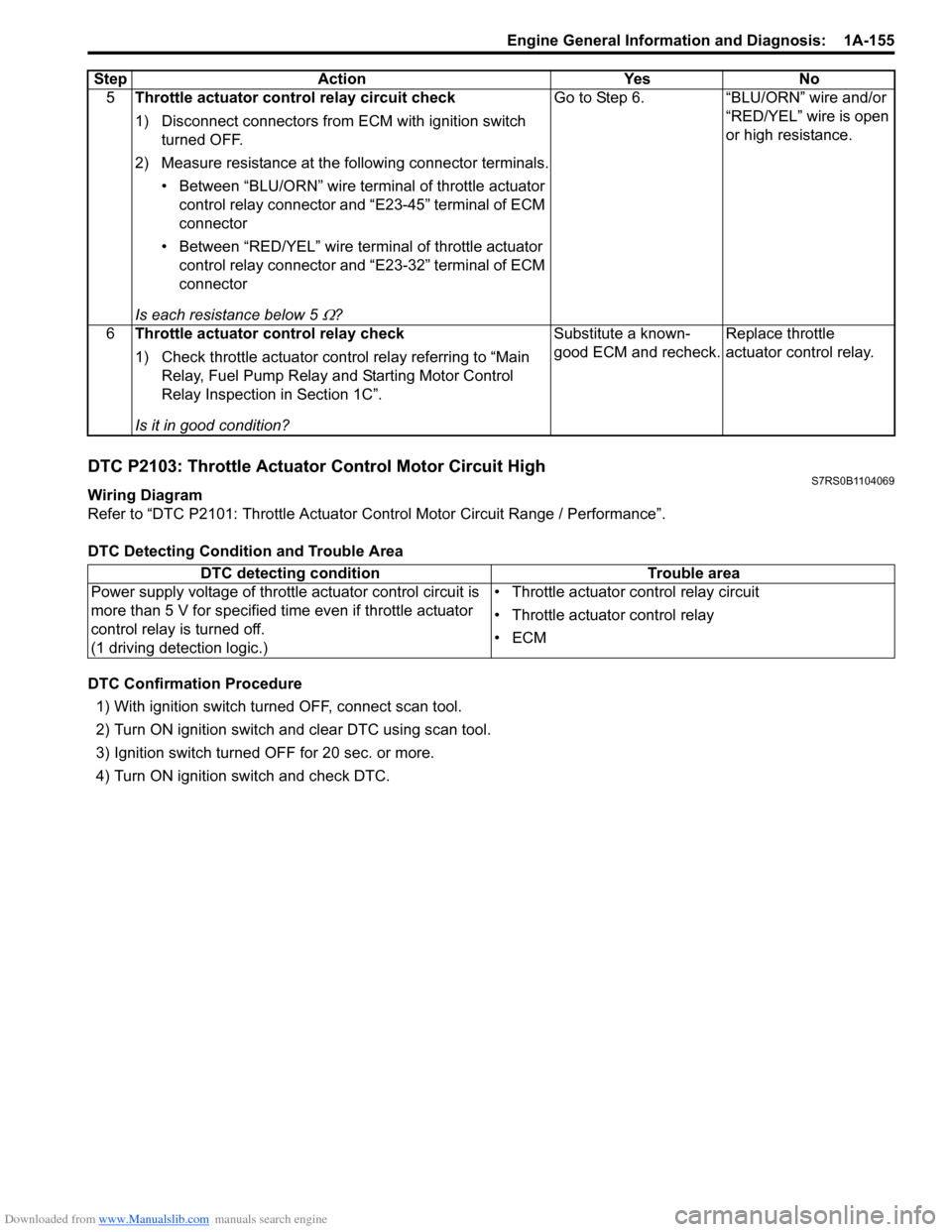
DTC detecting condition Trouble area
Power supply voltage of throttle actuator control circuit is
more than 5 V for specified time even if throttle actuator
control relay is turned off.
(1 driving detection logic.) • Throttle actuator control relay circuit
• Throttle actuator control relay
•ECM
Page 206 of 1496

Downloaded from www.Manualslib.com manuals search engine 1A-156 Engine General Information and Diagnosis:
DTC Troubleshooting
NOTE
• When measuring circuit voltage, resistance and/or pulse signal at ECM connector, connect the
special tool to ECM and/or the ECM connectors re ferring to “Inspection of ECM and Its Circuits”.
• Upon completion of inspection and repair work, perform “DTC Confirmation Procedure” and confirm that the trouble has been corrected.
DTC P2111 / P2112: Throttle Actuator Control System - Stuck Open / ClosedS7RS0B1104070
DTC Detecting Condition and Trouble Area
DTC Confirmation Procedure
1) With ignition switch turned OFF, connect scan tool.
2) Turn ON ignition switch and clear DTC using scan tool.
3) Ignition switch turned OFF for 20 sec. or more.
4) Turn ON ignition switch and check DTC.
Step Action Yes No
1 Was “Engine and Emission Control System Check”
performed? Go to Step 2. Go to “Engine and
Emission Control
System Check”.
2 Throttle actuator cont rol relay circuit check
1) Remove throttle actuator co ntrol relay from individual
circuit fuse box No.1 with ignition switch turned OFF.
2) Check for proper connection to throttle actuator control relay “BLK/RED”, “YEL/BLU”, “BLU/ORN” and “RED/
YEL” wire terminals.
3) Turn ON ignition switch.
4) Measure voltage between engine ground and “E23-32” terminal of ECM connector.
Is voltage 0 V? Go to Step 3. “RED/YEL” wire is
shorted to other circuit.
3 Throttle actuator cont rol relay circuit check
1) Disconnect connectors from ECM with ignition switch turned OFF.
2) Measure resistance between engine ground and “E23- 45” terminal of ECM connector.
Is resistance infinity? Go to Step 4. “BLU/ORN” wire is
shorted to ground
circuit.
4 Throttle actuator control relay check
1) Check throttle actuator control relay referring to “Main Relay, Fuel Pump Relay an d Starting Motor Control
Relay Inspection in Section 1C”.
Is it in good condition? Substitute a known-
good ECM and recheck.
Replace throttle
actuator control relay.
DTC detecting condition
Trouble area
P2111:
Throttle valve default opening is greater than 6 ° from
complementary closed position when diagnosing throttle
valve at ignition switch turned OFF.
(1 driving detection logic)
P2112:
Throttle valve default opening is smaller than 6 ° from
complementary closed position when diagnosing throttle
valve at ignition switch turned OFF.
(1 driving detection logic) • Electric throttle body
•ECM