2006 SUZUKI SWIFT Stepper
[x] Cancel search: StepperPage 66 of 1496
Downloaded from www.Manualslib.com manuals search engine 1A-16 Engine General Information and Diagnosis:
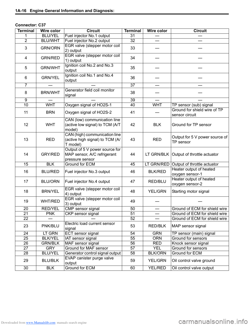
Connector: C37Terminal Wire color Circuit Terminal Wire color Circuit 1 BLU/YEL Fuel injector No.1 output 31 — —
2 BLU/WHT Fuel injector No.2 output 32 — —
3GRN/ORN EGR valve (stepper motor coil
2) output 33 — —
4 GRN/RED EGR valve (stepper motor coil
1) output 34 — —
5 GRN/WHT Ignition coil No.2 and No.3
output 35 — —
6 GRN/YEL Ignition coil No.1 and No.4
output 36 — —
7— — 37— —
8 BRN/WHT Generator field coil monitor
signal 38 — —
9— — 39— —
10 WHT Oxygen signal of HO2S-1 40 WHT TP sensor (sub) signal
11 BRN Oxygen signal of HO2S-2 41 — Ground for shield wire of TP
sensor circuit
12 WHT CAN (low) communication line
(active low signal) to TCM (A/T
model) 42 BLK Ground for TP sensor
13 RED CAN (high) communication line
(active high signal) to TCM (A/
T model) 43 RED
Output for 5 V power source of
TP sensor
14 GRY/RED Output of 5 V power source for
MAP sensor, A/C refrigerant
pressure sensor 44 LT GRN/BLK Output of throttle actuator
15 BLK Ground for ECM 45 LT GRN/RE D Output of throttle actuator
16 BLU/RED Fuel injector No.3 output 46 BLK/RED Heater output of heated
oxygen sensor-1
17 BLU/ORN Fuel injector No.4 output 47 RED/BLU Heater output of heated
oxygen sensor-2
18 BRN/YEL EGR valve (stepper motor coil
4) output 48 YEL/GRN Starting motor signal
19 WHT/RED EGR valve (stepper motor coil
3) output 49 — —
20 RED/YEL CMP sensor signal 50 — G round of ECM for shield wire
21 PNK CKP sensor signal 51 — Ground of ECM for shield wire
22 — — 52 — Ground of ECM for shield wire
23 PNK/BLU Electric load current sensor
signal 53 RED/BLK MAP sensor signal
24 LT GRN ECT sensor signal 54 GRN TP sensor (main) signal
25 BLK/YEL IAT sensor signal 55 ORN Ground for sensors
26 GRN/BLK MAF sensor signal 56 RED Knock sensor signal
27 GRY Ground for MAF sensor 57 YEL Ground for sensors
28 BLU/YEL Generator control signal output 58 BLK/ORN Ground for ECM
29 BLU/BLK EVAP canister purge valve
output 59 YEL/GRN Oil control valve ground
30 BLK Ground for ECM 60 YEL/RED Oil control valve output
Page 169 of 1496
Downloaded from www.Manualslib.com manuals search engine Engine General Information and Diagnosis: 1A-119
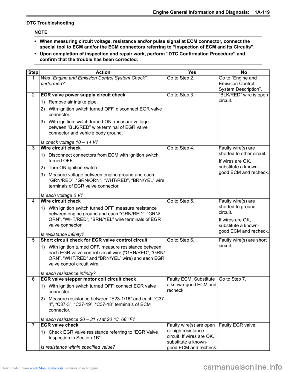
DTC Troubleshooting
NOTE
• When measuring circuit voltage, resistance and/or pulse signal at ECM connector, connect the
special tool to ECM and/or the ECM connectors re ferring to “Inspection of ECM and Its Circuits”.
• Upon completion of inspection and repair work, perform “DTC Confirmation Procedure” and confirm that the trouble has been corrected.
Step Action YesNo
1 Was “Engine and Emission Control System Check”
performed? Go to Step 2.
Go to “Engine and
Emission Control
System Description”.
2 EGR valve power supply circuit check
1) Remove air intake pipe.
2) With ignition switch turned OFF, disconnect EGR valve
connector.
3) With ignition switch turned ON, measure voltage between “BLK/RED” wire terminal of EGR valve
connector and vehicle body ground.
Is check voltage 10 – 14 V? Go to Step 3.
“BLK/RED” wire is open
circuit.
3 Wire circuit check
1) Disconnect connectors from ECM with ignition switch
turned OFF.
2) Turn ON ignition switch.
3) Measure voltage between engine ground and each “GRN/RED”, “GRN/ORN”, “W HT/RED”, “BRN/YEL” wire
terminals of EGR valve connector.
Is each voltage 0 V? Go to Step 4.
Faulty wire(s) are
shorted to other circuit.
If wires are OK,
substitute a known-
good ECM and recheck.
4 Wire circuit check
1) With ignition switch turned OFF, measure resistance
between engine ground and each “GRN/RED”, “GRN/
ORN”, “WHT/RED”, “BRN/YEL” wire terminals of EGR
valve connector.
Is resistance infinity? Go to Step 5.
Faulty wire(s) are
shorted to ground
circuit.
If wires are OK,
substitute a known-
good ECM and recheck.
5 Short circuit check for EGR valve control circuit
1) With ignition turned OFF, measure resistance between
each EGR valve control circ uit wire (“GRN/RED”, “GRN/
ORN”, “WHT/RED” and “BRN/ YEL” wire) and each EGR
valve control circuit wire.
Is each resistance infinity? Go to Step 6.
Faulty wire(s) are short
circuit.
6 EGR valve stepper motor coil circuit check
1) With ignition switch turned OFF, connect EGR valve
connector.
2) Measure resistance between “E23-1/16” and each “C37- 4”, “C37-3”, “C37-19”, “C37-18” terminals of ECM
connector.
Is each resistance 20 – 31
Ω at 20 °C, 68 °F? Faulty ECM. Substitute
a known-good ECM and
recheck.
Go to Step 7.
7 EGR valve check
1) Check EGR valve resistance referring to “EGR Valve
Inspection in Section 1B”.
Is resistance within specified value? Faulty wire(s) are open
or high resistance
circuit. If wires are OK,
substitute a known-
good ECM and recheck.Faulty EGR valve.
Page 226 of 1496
Downloaded from www.Manualslib.com manuals search engine 1A-176 Engine General Information and Diagnosis:
Terminal No. Wire
color Circuit Normal voltage Condition Remarks
C37-1 BLU/
YEL Fuel injector No.1
output 10 – 14 V Ignition switch turned ON. —
*0 – 0.6 V ↑↓
10 – 14 V
(“Reference
waveform No.1: ”,
“Reference waveform No.2: ” and
“Reference waveform No.22: ”) Engine running at idle
after warmed up engine.
Output signal is active low
pulse. Pulse frequency
varies depending on
engine speed.
C37-2 BLU/
WHT Fuel injector No.2
output 10 – 14 V Ignition switch turned ON. —
*0 – 0.6 V ↑↓
10 – 14 V
(“Reference
waveform No.1: ” and
“Reference waveform No.3: ”) Engine running at idle
after warmed up engine.
Output signal is active low
pulse. Pulse frequency
varies depending on
engine speed.
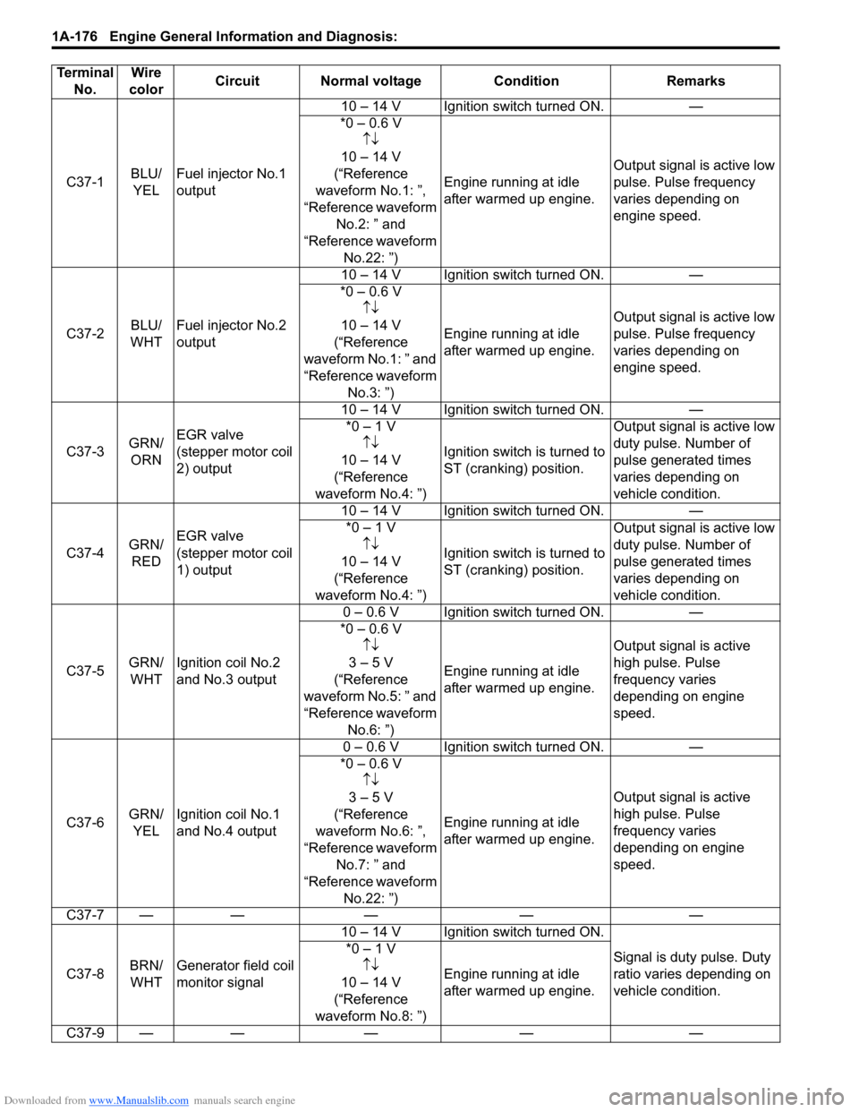
C37-3 GRN/
ORN EGR valve
(stepper motor coil
2) output 10 – 14 V Ignition switch turned ON. —
*0 – 1 V ↑↓
10 – 14 V
(“Reference
waveform No.4: ”) Ignition switch is turned to
ST (cranking) position. Output signal is active low
duty pulse. Number of
pulse generated times
varies depending on
vehicle condition.
C37-4 GRN/
RED EGR valve
(stepper motor coil
1) output 10 – 14 V Ignition switch turned ON. —
*0 – 1 V
↑↓
10 – 14 V
(“Reference
waveform No.4: ”) Ignition switch is turned to
ST (cranking) position. Output signal is active low
duty pulse. Number of
pulse generated times
varies depending on
vehicle condition.
C37-5 GRN/
WHT Ignition coil No.2
and No.3 output 0 – 0.6 V Ignition switch turned ON. —
*0 – 0.6 V ↑↓
3 – 5 V
(“Reference
waveform No.5: ” and
“Reference waveform No.6: ”) Engine running at idle
after warmed up engine.
Output signal is active
high pulse. Pulse
frequency varies
depending on engine
speed.
C37-6 GRN/
YEL Ignition coil No.1
and No.4 output 0 – 0.6 V Ignition switch turned ON. —
*0 – 0.6 V ↑↓
3 – 5 V
(“Reference
waveform No.6: ”,
“Reference waveform No.7: ” and
“Reference waveform No.22: ”
)Engine running at idle
after warmed up engine.
Output signal is active
high pulse. Pulse
frequency varies
depending on engine
speed.
C37-7 — —— — —
C37-8 BRN/
WHT Generator field coil
monitor signal 10 – 14 V Ignition switch turned ON.
Signal is duty pulse. Duty
ratio varies depending on
vehicle condition.
*0 – 1 V
↑↓
10 – 14 V
(“Reference
waveform No.8: ”) Engine running at idle
after warmed up engine.
C37-9 — —— — —
Page 227 of 1496
Downloaded from www.Manualslib.com manuals search engine Engine General Information and Diagnosis: 1A-177
C37-10 WHTOxygen signal of
HO2S-1 0 – 1 V Ignition switch turned ON.
—
*Deflects between
over 0.5 V and under 0.45 V
(“Reference
waveform No.10: ” and “Reference
waveform No.11: ”) While engine running at
2,000 r/min. for 1 min. or
longer after warmed up.
C37-11 BRN Oxygen signal of
HO2S-2 4 – 5 V Ignition switch turned ON.
—
*Deflects between
over 0.5 V and under 0.45 V
(“Reference
waveform No.12: ”) While engine running at
2,000 r/min. or more after
vehicle running over 30
km/h, 19 mph for 5 min.
C37-12 WHT CAN (low)
(communication
line (active low
signal) to TCM (A/T
model) *0.5 – 2.5 V
(“Reference
waveform No.13: ”) Ignition switch turned ON
with engine stop. CAN communication line
signal is pulse. Pulse
signal displayed with a
regular frequency which
varies depending on
engine condition.
C37-13 RED CAN (high)
communication line
(active high signal)
to TCM (A/T
model) *2.5 – 4.5 V
(“Reference
waveform No.13: ”)
C37-14 GRY/
RED Output of 5 V
power source for
MAP sensor, A/C
refrigerant
pressure sensor
4.5 – 5.5 V Ignition switch turned ON. —
C37-15 BLK Ground for ECM Below 0.3 V Ignition switch turned ON. —
C37-16 BLU/
RED Fuel injector No.3
output 10 – 14 V Ignition switch turned ON. —
*0 – 0.6 V ↑↓
10 – 14 V
(“Reference
waveform No.1: ” and
“Reference waveform No.14: ”) Engine running at idle
after warmed up engine.
Output signal is active low
pulse. Pulse frequency
varies depending on
engine speed.
C37-17 BLU/
ORNFuel injector No.4
output 10 – 14 V Ignition switch turned ON. —
*0 – 0.6 V ↑↓
10 – 14 V
(“Reference
waveform No.1: ” and
“Reference waveform No.15: ”) Engine running at idle
after warmed up engine.
Output signal is active low
pulse. Pulse frequency
varies depending on
engine speed.
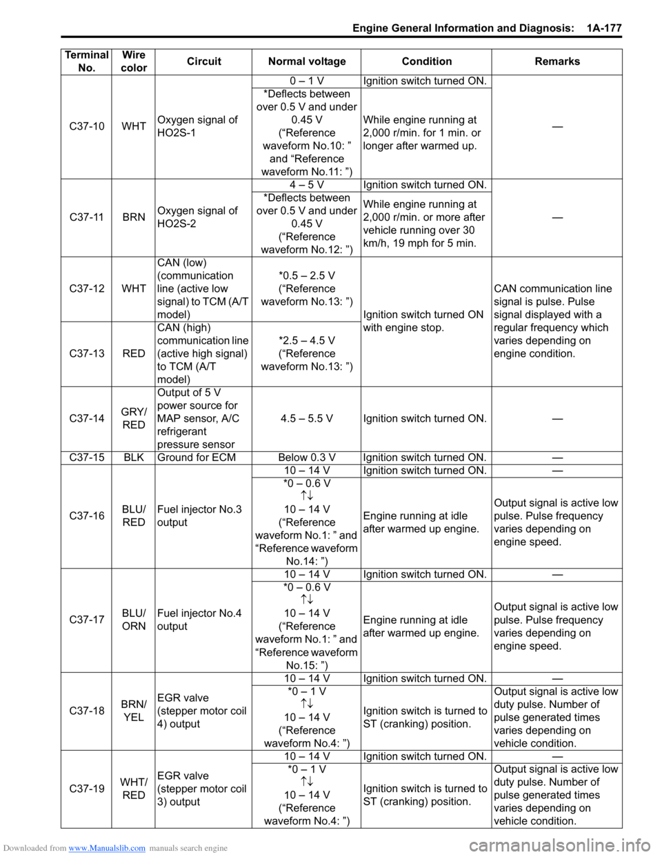
C37-18 BRN/
YEL EGR valve
(stepper motor coil
4) output 10 – 14 V Ignition switch turned ON. —
*0 – 1 V ↑↓
10 – 14 V
(“Reference
waveform No.4: ”) Ignition switch is turned to
ST (cranking) position. Output signal is active low
duty pulse. Number of
pulse generated times
varies depending on
vehicle condition.
C37-19 WHT/
RED EGR valve
(stepper motor coil
3) output 10 – 14 V Ignition switch turned ON. —
*0 – 1 V ↑↓
1
0 – 14 V
(“Reference
waveform No.4: ”) Ignition switch is turned to
ST (cranking) position. Output signal is active low
duty pulse. Number of
pulse generated times
varies depending on
vehicle condition.
Terminal
No. Wire
color Circuit Normal voltage
ConditionRemarks
Page 235 of 1496
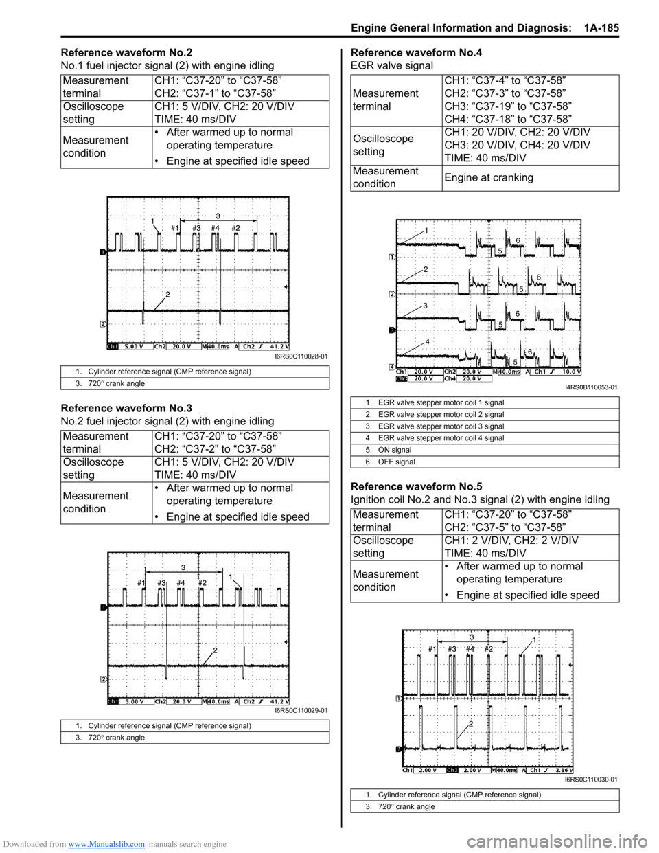
Downloaded from www.Manualslib.com manuals search engine Engine General Information and Diagnosis: 1A-185
Reference waveform No.2
No.1 fuel injector signal (2) with engine idling
Reference waveform No.3
No.2 fuel injector sig nal (2) with engine idling Reference waveform No.4
EGR valve signal
Reference waveform No.5
Ignition coil No.2 and No.3 signal (2) with engine idling
Measurement
terminal
CH1: “C37-20” to “C37-58”
CH2: “C37-1” to “C37-58”
Oscilloscope
setting CH1: 5 V/DIV, CH2: 20 V/DIV
TIME: 40 ms/DIV
Measurement
condition • After warmed up to normal
operating temperature
• Engine at specified idle speed
1. Cylinder reference signal (CMP reference signal)
3. 720 ° crank angle
Measurement
terminal CH1: “C37-20” to “C37-58”
CH2: “C37-2” to “C37-58”
Oscilloscope
setting CH1: 5 V/DIV, CH2: 20 V/DIV
TIME: 40 ms/DIV
Measurement
condition • After warmed up to normal
operating temperature
• Engine at specified idle speed
1. Cylinder reference signal (CMP reference signal)
3. 720 ° crank angle
I6RS0C110028-01
I6RS0C110029-01
Measurement
terminal CH1: “C37-4” to “C37-58”
CH2: “C37-3” to “C37-58”
CH3: “C37-19” to “C37-58”
CH4: “C37-18” to “C37-58”
Oscilloscope
setting CH1: 20 V/DIV, CH2: 20 V/DIV
CH3: 20 V/DIV, CH4: 20 V/DIV
TIME: 40 ms/DIV
Measurement
condition Engine at cranking
1. EGR valve stepper motor coil 1 signal
2. EGR valve stepper motor coil 2 signal
3. EGR valve stepper motor coil 3 signal
4. EGR valve stepper motor coil 4 signal
5. ON signal
6. OFF signal
Measurement
terminalCH1: “C37-20” to “C37-58”
CH2: “C37-5” to “C37-58”
Oscilloscope
setting CH1: 2 V/DIV, CH2: 2 V/DIV
TIME: 40 ms/DIV
Measurement
condition • After warmed up to normal
operating temperature
• Engine at specified idle speed
1. Cylinder reference signal (CMP reference signal)
3. 720 ° crank angle
I4RS0B110053-01
I6RS0C110030-01
Page 1182 of 1496

Downloaded from www.Manualslib.com manuals search engine 9A-11 Wiring Systems:
C: Engine harnessNo./Color Connective position No./Color Connective positionC01/GRY IAC valve C22/- Generator #2
C02/GRY IG Coil #1 C23/BLK Starting motor #1
C03/GRY IG Coil #2 C24/- Starting motor #2
C04/GRY Fuel injector #1 C25/GR Y VSS (Vehicle speed sensor)
C05/GRY Fuel injector #2 C26/GRY Knock sensor
C06/GRY Fuel injector #3 C27/BLU (A/
T) Input shaft speed sensor
C07/GRY Fuel injector #4 C28/GRY
(A/T) Trans axle range sensor
C08/BLK or GRY CMP sensor C29/GRY
(A/T) Shift solenoid
C09/BLK ECT sensor C30/BLK
(M/T) Back-up light switch
C10/GRY EGR stepper motor C31/- Main fuse box C11/BLK Throttle position sensor C32/GRY
(IF EQPD) Current sensor
C12/BLK MAP sensor C33/- Main fuse box
C13/BLK MAF sensor C34/N (A/T) TCM
C14/BLK EVAP canister purge valve C35/N (A/T) TCM
C15/GRY Heated oxygen sensor #1 C36/N Main harness (To E24)
C16/GRN Heated oxygen sensor #2 C37/GRY ECM C17/BLK A/C compressor C38/- Weld splice C18/N Oil pressure switch C39/- Weld splice
C19/BLU VVT solenoid C40/- Weld splice
C20/GRY CKP sensor C41/- Weld splice
C21/GRY or BLK Generator #1
Page 1184 of 1496

Downloaded from www.Manualslib.com manuals search engine 9A-13 Wiring Systems:
C: Engine harness
D: Oil pressure switch wireNo./Color Connective position No./Color Connective position
C02/GRY IG Coil #1 C24/- Starting motor #2
C03/GRY IG Coil #2 C23/BLK Starting motor #1
C04/GRY Fuel injector #1 C25/GRY
(A/T) VSS (Vehicle speed sensor)
C05/GRY Fuel injector #2 C26/GRY Knock shaft speed sensor
C06/GRY Fuel injector #3 C27/BLU (A/
T) Input shaft speed sensor
C07/GRY Fuel injector #4 C28/GRY
(A/T) Trans axle range sensor
C08/BLK CMP sensor C29/GRY
(A/T) Shift solenoid
C09/BLK ECT sensor C30/BLK
(M/T) Back-up light switch
C10/GRY EGR stepper motor C31/- Main fuse box C12/BLK MAP sensor C32/GRY Current sensor
C13/BLK MAF sensor C33/- Main fuse box
C14/BLK EVAP canister purge valve C34/N (A/T) TCM
C15/BLK Heated oxygen sensor #1 C35/N (A/T) TCM
C16/GRN Heated oxygen sensor #2 C36/N Main harness (To E24) C17/BLK A/C compressor C37/GRY ECM C18/N Oil pressure switch wire (To D02) C38/- Weld splice
C19/BLU VVT solenoid C39/- Weld splice
C20/GRY CKP sensor C40/- Weld splice C21/BLK Generator #1 C42/BLK Electric throttle body C22/- Generator #2
No./Color Connective position No./ColorConnective position
D01/N Oil pressure switch D02/GRY Engine harness (To C18)
Page 1223 of 1496
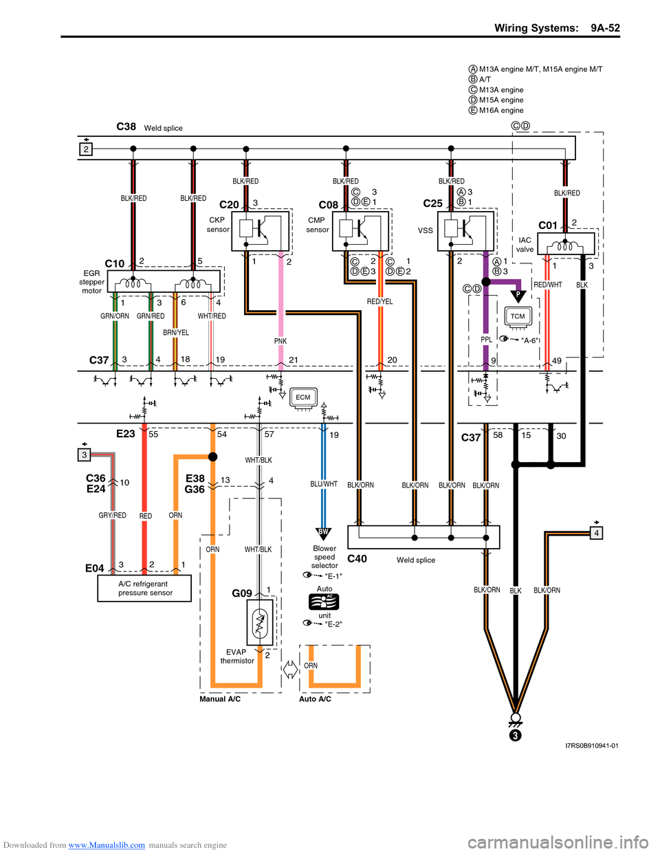
Downloaded from www.Manualslib.com manuals search engine Wiring Systems: 9A-52
"E-1"
"E-2"
EGR
stepper motor
PPL
P
"A-6"
AB
AB
CD
CD
ECM
2
3
REDORNGRY/RED
EVAP
thermistor
1
2G09
13
ORN
ORN
E38
G36
BW
Blower
speed
selector
Auto
unit
A/C refrigerant
pressure sensor
E04
C10
BRN/YEL
WHT/REDGRN/RED
6
4312
5
CKP
sensor CMP
sensor VSS
TCM
C37
BLK
3
155830
C25
21
3CDE12CDE23 3
1
CDE31
1 2
3
C08
C20
C37
18 19
4320
219
PNK
RED/YEL
E2354
55
C36
E2410
1
2
3
19
4
RED/WHT
49
BLK/RED
BLK
C012
1 3
IAC
valve
BLU/WHT
GRN/ORN
WHT/BLK
57
4
WHT/BLK
BLK/RED
BLK/ORNBLK/ORNBLK/ORNBLK/ORN
C40Weld splice
BLK/ORNBLK/ORN
C38Weld splice
BLK/REDBLK/RED
BLK/REDBLK/RED
M13A engine M/T, M15A engine M/T
A/T
M13A engine
M15A engine
M16A engine
ABCDE
Manual A/C
Auto A/C
I7RS0B910941-01