2006 SUZUKI SWIFT Coupler
[x] Cancel search: CouplerPage 1290 of 1496
Downloaded from www.Manualslib.com manuals search engine 9B-8 Lighting Systems:
Headlight Switch (in Lighting Switch) Removal
and Installation
S7RS0B9206004
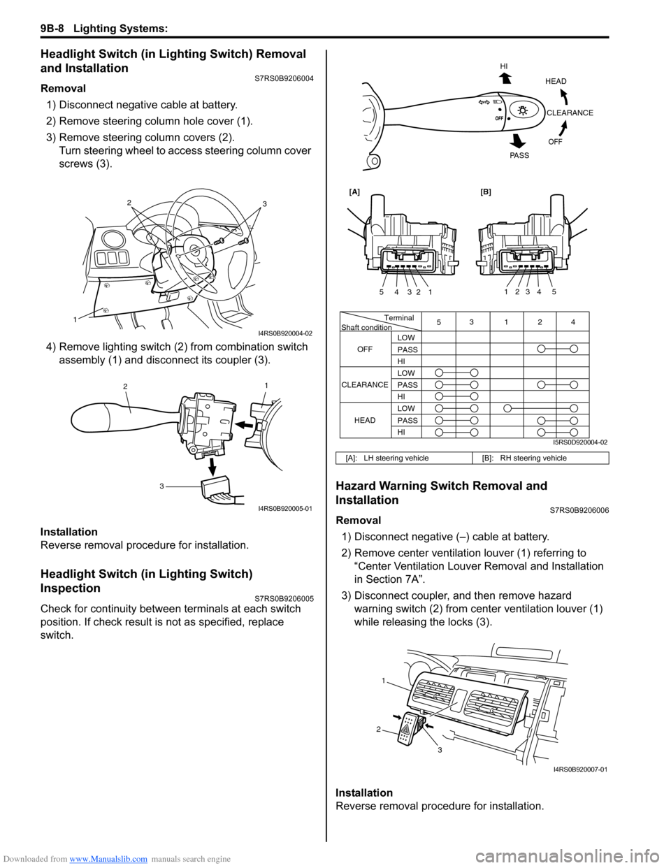
Removal1) Disconnect negative cable at battery.
2) Remove steering column hole cover (1).
3) Remove steering column covers (2). Turn steering wheel to acce ss steering column cover
screws (3).
4) Remove lighting switch (2 ) from combination switch
assembly (1) and disconnect its coupler (3).
Installation
Reverse removal procedure for installation.
Headlight Switch (in Lighting Switch)
Inspection
S7RS0B9206005
Check for continuity between terminals at each switch
position. If check result is not as specified, replace
switch.
Hazard Warning Switch Removal and
Installation
S7RS0B9206006
Removal 1) Disconnect negative (–) cable at battery.
2) Remove center ventilation louver (1) referring to
“Center Ventilation Louver Removal and Installation
in Section 7A”.
3) Disconnect coupler, and then remove hazard warning switch (2) from center ventilation louver (1)
while releasing the locks (3).
Installation
Reverse removal procedure for installation.
1
32
I4RS0B920004-02
1
2
3
I4RS0B920005-01
[A]: LH steering vehicle [B]: RH steering vehicle
Terminal
Shaft condition
OFF 5
3124
LOW
PASS
HI
LOW
PASS
HI LOW
PASS
HI
CLEARANCE
HEAD
HEADCLEARANCE
OFF
HI
PA S S
54321
54321
[A][B]
I5RS0D920004-02
1
2 3
I4RS0B920007-01
Page 1292 of 1496
Downloaded from www.Manualslib.com manuals search engine 9B-10 Lighting Systems:
Turn Signal and Hazard Warning Relay
Inspection
S7RS0B9206012
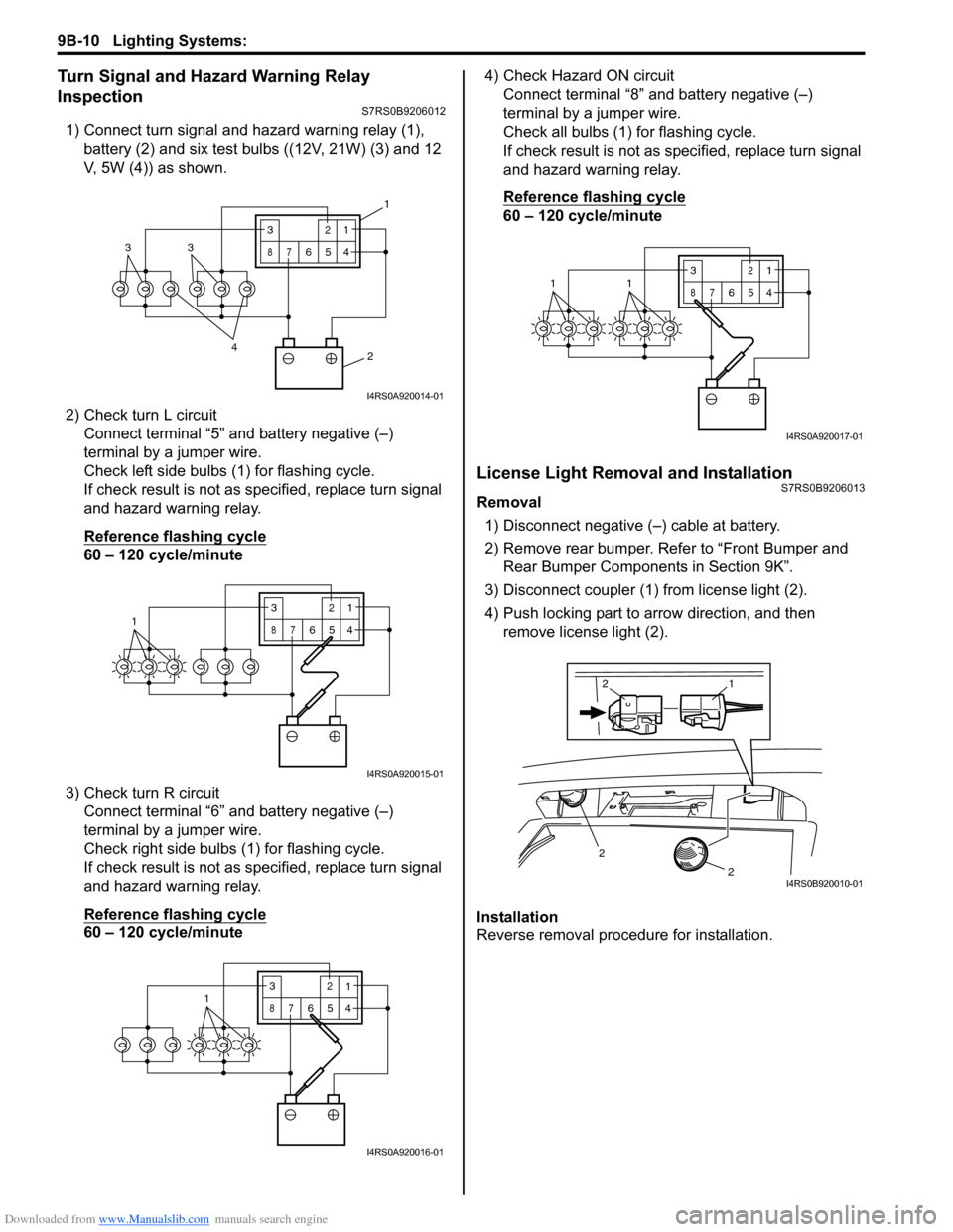
1) Connect turn signal and hazard warning relay (1), battery (2) and six test bulbs ((12V, 21W) (3) and 12
V, 5W (4)) as shown.
2) Check turn L circuit Connect terminal “5” and battery negative (–)
terminal by a jumper wire.
Check left side bulbs (1) for flashing cycle.
If check result is not as specified, replace turn signal
and hazard warning relay.
Reference flashing cycle
60 – 120 cycle/minute
3) Check turn R circuit Connect terminal “6” and battery negative (–)
terminal by a jumper wire.
Check right side bulbs (1) for flashing cycle.
If check result is not as specified, replace turn signal
and hazard warning relay.
Reference flashing cycle
60 – 120 cycle/minute 4) Check Hazard ON circuit
Connect terminal “8” and battery negative (–)
terminal by a jumper wire.
Check all bulbs (1) for flashing cycle.
If check result is not as sp ecified, replace turn signal
and hazard warning relay.
Reference flashing cycle
60 – 120 cycle/minute
License Light Removal and InstallationS7RS0B9206013
Removal
1) Disconnect negative (–) cable at battery.
2) Remove rear bumper. Refe r to “Front Bumper and
Rear Bumper Components in Section 9K”.
3) Disconnect coupler (1) from license light (2).
4) Push locking part to arrow direction, and then remove license light (2).
Installation
Reverse removal procedure for installation.
2
4
33
3
87
12
654
1
I4RS0A920014-01
13
87
12
654
I4RS0A920015-01
3
87
12
6541
I4RS0A920016-01
3
87
12
6
5411
I4RS0A920017-01
2
2
1
2
I4RS0B920010-01
Page 1293 of 1496
Downloaded from www.Manualslib.com manuals search engine Lighting Systems: 9B-11
Front Fog Light Removal and Installation (If
Equipped)
S7RS0B9206014
Removal1) Disconnect negative (–) cable at battery.
2) Remove front bumper, and then remove front bumper guard from front bumper referring to “Front
Bumper and Rear Bumper Components in Section
9K”.
3) Disconnect coupler from fog light.
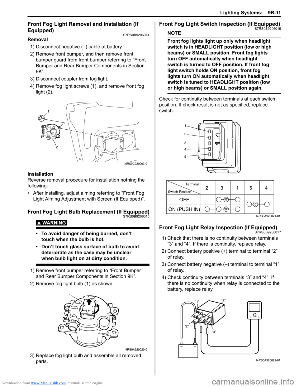
4) Remove fog light screws (1), and remove front fog light (2).
Installation
Reverse removal procedure for installation nothing the
following:
• After installing, adjust aimi ng referring to “Front Fog
Light Aiming Adjustment with Screen (If Equipped)”.
Front Fog Light Bulb Replacement (If Equipped)S7RS0B9206015
WARNING!
• To avoid danger of being burned, don’t touch when the bulb is hot.
• Don’t touch glass surface of bulb to avoid deteriorate as the case may be unclear
when bulb light on at dirty condition.
1) Remove front bumper referring to “Front Bumper and Rear Bumper Components in Section 9K”.
2) Remove fog light bulb (1) as shown.
3) Replace fog light bulb and assemble all removed parts.
Front Fog Light Switch Inspection (If Equipped)S7RS0B9206016
NOTE
Front fog lights light up only when headlight
switch is in HEADLIGHT position (low or high
beams) or SMALL position. Front fog lights
turn OFF automatically when headlight
switch is turned to OFF position. If front fog
light switch holds ON position, front fog
lights turn ON automa tically when headlight
switch is tuned to HEADLIGHT position (low
or high beams) or SMALL position again.
Check for continuity between terminals at each switch
position. If check result is not as specified, replace
switch.
Front Fog Light Relay Inspection (If Equipped)S7RS0B9206017
1) Check that there is no continuity between terminals “3” and “4”. If there is continuity, replace relay.
2) Connect battery positive (+ ) terminal to terminal “2”
of relay.
3) Connect battery negative (–) terminal to terminal “1” of relay.
4) Check continuity between terminals “3” and “4”. If there is no continuity when relay is connected to the
battery, replace relay.
1
2
I6RS0C920003-01
1
I4RS0A920020-01
1
2
3
4
5
Switch Position Terminal
ON (PUSH IN) 23
1
54
OFF
I4RS0A920021-01
“4”
“2” “1”
“3”
I4RS0A920022-01
Page 1295 of 1496
Downloaded from www.Manualslib.com manuals search engine Lighting Systems: 9B-13
Headlight Leveling Switch Inspection (If
Equipped)
S7RS0B9206019
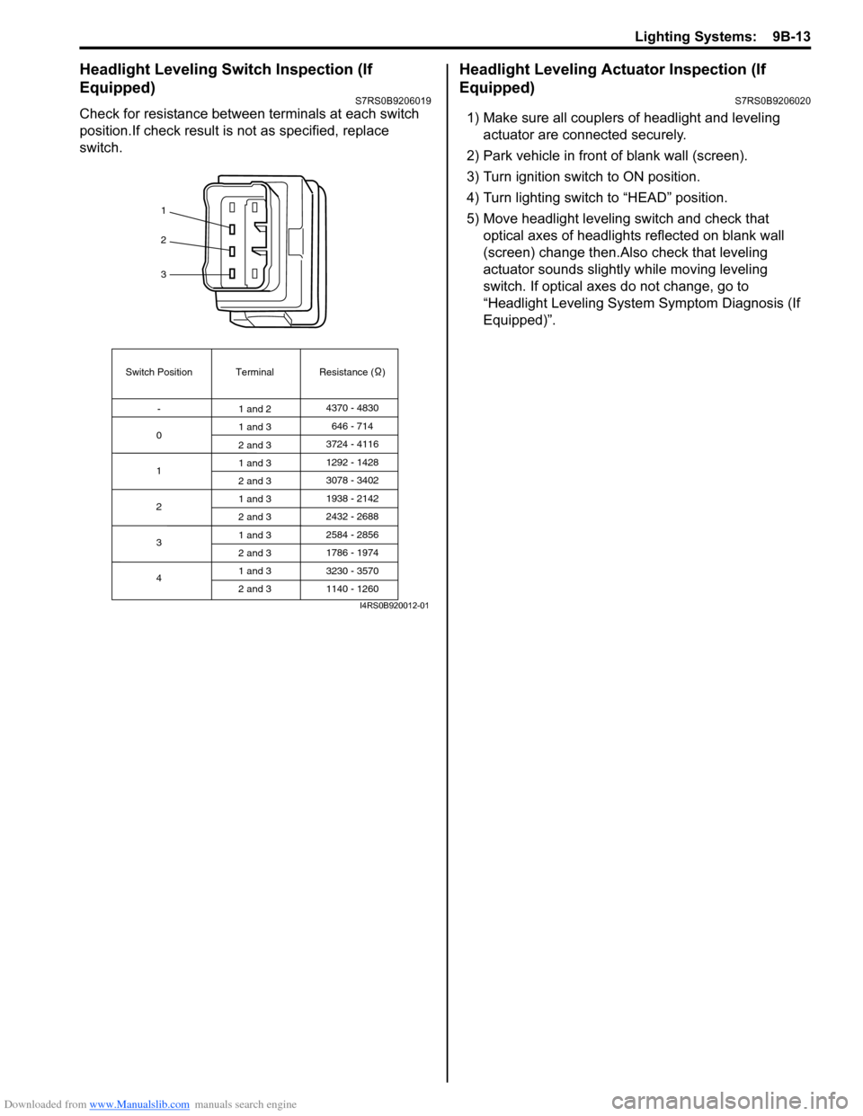
Check for resistance between terminals at each switch
position.If check result is not as specified, replace
switch.
Headlight Leveling Actuator Inspection (If
Equipped)
S7RS0B9206020
1) Make sure all couplers of headlight and leveling actuator are connected securely.
2) Park vehicle in front of blank wall (screen).
3) Turn ignition switch to ON position.
4) Turn lighting switch to “HEAD” position.
5) Move headlight leveling switch and check that
optical axes of headlights reflected on blank wall
(screen) change then.Also check that leveling
actuator sounds slightly while moving leveling
switch. If optical axes do not change, go to
“Headlight Leveling System Symptom Diagnosis (If
Equipped)”.
1
2
3
Switch Position
0 Terminal Resistance ( )
-
1
2
3
4 1 and 2
4370 - 4830
1 and 3
2 and 3
1 and 3
2 and 3
1 and 3
2 and 3
1 and 3
2 and 3
1 and 3
2 and 3 646 - 714
3724 - 4116
3078 - 3402 1292 - 1428
1938 - 2142
2584 - 2856
3230 - 3570 2432 - 2688
1786 - 1974
1140 - 1260
I4RS0B920012-01
Page 1300 of 1496
Downloaded from www.Manualslib.com manuals search engine 9C-5 Instrumentation / Driver Info. / Horn:
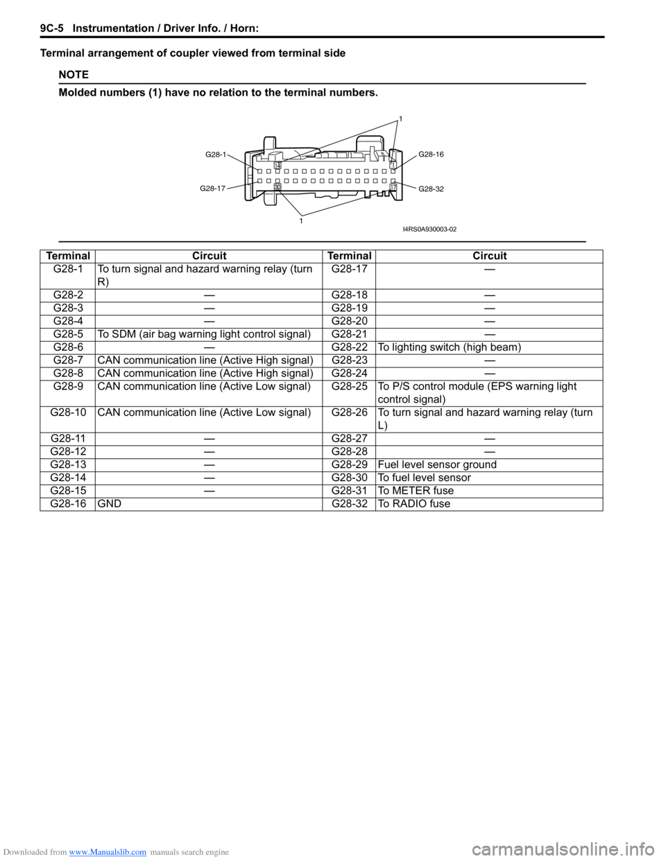
Terminal arrangement of coupler viewed from terminal side
NOTE
Molded numbers (1) have no relation to the terminal numbers.
TerminalCircuitTerminal Circuit
G28-1 To turn signal and hazard warning relay (turn R) G28-17
—
G28-2 —G28-18 —
G28-3 —G28-19 —
G28-4 —G28-20 —
G28-5 To SDM (air bag warning light control signal) G28-21 —
G28-6 —G28-22 To lighting switch (high beam)
G28-7 CAN communication line (Active High signal) G28-23 —
G28-8 CAN communication line (Active High signal) G28-24 —
G28-9 CAN communication line (Active Low signal) G 28-25 To P/S control module (EPS warning light
control signal)
G28-10 CAN communication line (Active Low signal) G28-26 To turn signal and hazard warning relay (turn L)
G28-11 —G28-27 —
G28-12 —G28-28 —
G28-13 —G28-29 Fuel level sensor ground
G28-14 —G28-30 To fuel level sensor
G28-15 —G28-31 To METER fuse
G28-16 GND G28-32 To RADIO fuse
G28-1 G28-16
G28-32
G28-17
1 1I4RS0A930003-02
Page 1309 of 1496
Downloaded from www.Manualslib.com manuals search engine Instrumentation / Driver Info. / Horn: 9C-14
Navigation Symptom Diagnosis (If Equipped)S7RS0B9304019
Repair Instructions
Ignition Switch Removal and InstallationS7RS0B9306001
Removal
1) Disconnect negative (–) cable at battery.
2) Confirm that ignition key is removed.
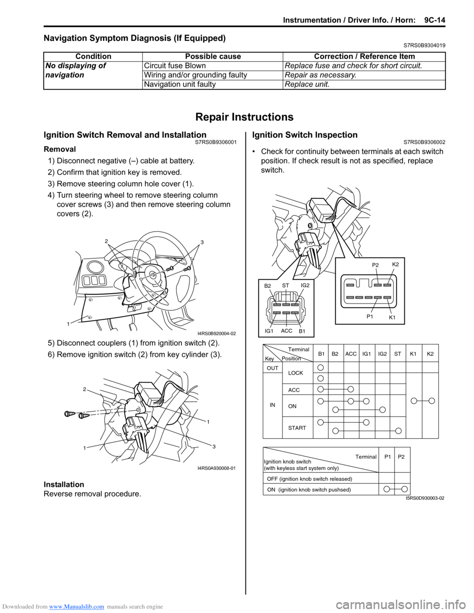
3) Remove steering column hole cover (1).
4) Turn steering wheel to remove steering column cover screws (3) and then remove steering column
covers (2).
5) Disconnect couplers (1) from ignition switch (2).
6) Remove ignition switch (2) from key cylinder (3).
Installation
Reverse removal procedure.
Ignition Switch InspectionS7RS0B9306002
• Check for continuity between terminals at each switch
position. If check result is not as specified, replace
switch.
Condition Possible cause Correction / Reference Item
No displaying of
navigation Circuit fuse Blown
Replace fuse and check for short circuit.
Wiring and/or grounding faulty Repair as necessary.
Navigation unit faulty Replace unit.
1
32
I4RS0B920004-02
1 1
2
3
I4RS0A930008-01
PositionTerminal
LOCK
ACC
ON
START
OUT
INK2K1ST
IG2
IG1
ACC
B1 B2
Ignition knob switch
(with keyless start system only)
ACC
IG1 IG2
ST
B2
B1 K2
K1
P2
P1
Terminal
OFF (ignition knob switch released) ON (ignition knob switch pushsed)P1 P2
Key
I5RS0D930003-02
Page 1311 of 1496
Downloaded from www.Manualslib.com manuals search engine Instrumentation / Driver Info. / Horn: 9C-16
Oil Pressure Switch InspectionS7RS0B9306007
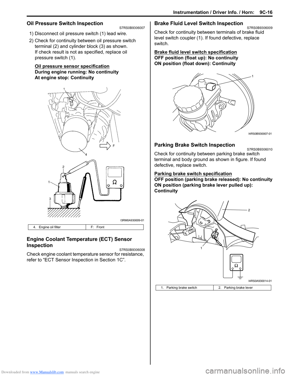
1) Disconnect oil pressure switch (1) lead wire.
2) Check for continuity between oil pressure switch terminal (2) and cylinder block (3) as shown.
If check result is not as specified, replace oil
pressure switch (1).
Oil pressure sensor specification
During engine running: No continuity
At engine stop: Continuity
Engine Coolant Temperature (ECT) Sensor
Inspection
S7RS0B9306008
Check engine coolant temperat ure sensor for resistance,
refer to “ECT Sensor Inspection in Section 1C”.
Brake Fluid Level Switch InspectionS7RS0B9306009
Check for continuity between terminals of brake fluid
level switch coupler (1). If found defective, replace
switch.
Brake fluid level switch specification
OFF position (float up): No continuity
ON position (float down): Continuity
Parking Brake Switch InspectionS7RS0B9306010
Check for continuity between parking brake switch
terminal and body ground as shown in figure. If found
defective, replace switch.
Parking brake switch specification
OFF position (parking brake released): No continuity
ON position (parking brake lever pulled up):
Continuity
4. Engine oil filter F: Front
I3RM0A930009-01
1. Parking brake switch 2. Parking brake lever
1
I4RS0B930007-01
12
I4RS0A930014-01
Page 1314 of 1496
Downloaded from www.Manualslib.com manuals search engine 9C-19 Instrumentation / Driver Info. / Horn:
Installation
Reverse removal procedure noting the following.
• When installing each part, be careful not to catch any
cable or wiring harness.
• Tighten instrument panel mounting bolts to specified
torque
Tightening torque
Instrument panel mounting bolt (a): 23 N·m (2.3
kgf-m, 17.0 lb-ft)
• Tighten steering column mounting nuts referring to “Steering Column Removal an d Installation in Section
6B”.
• Enable air bag system referring to “Enabling Air Bag System in Section 8B”.
Information Display (Clock) Removal and
Installation
S7RS0B9306016
Removal
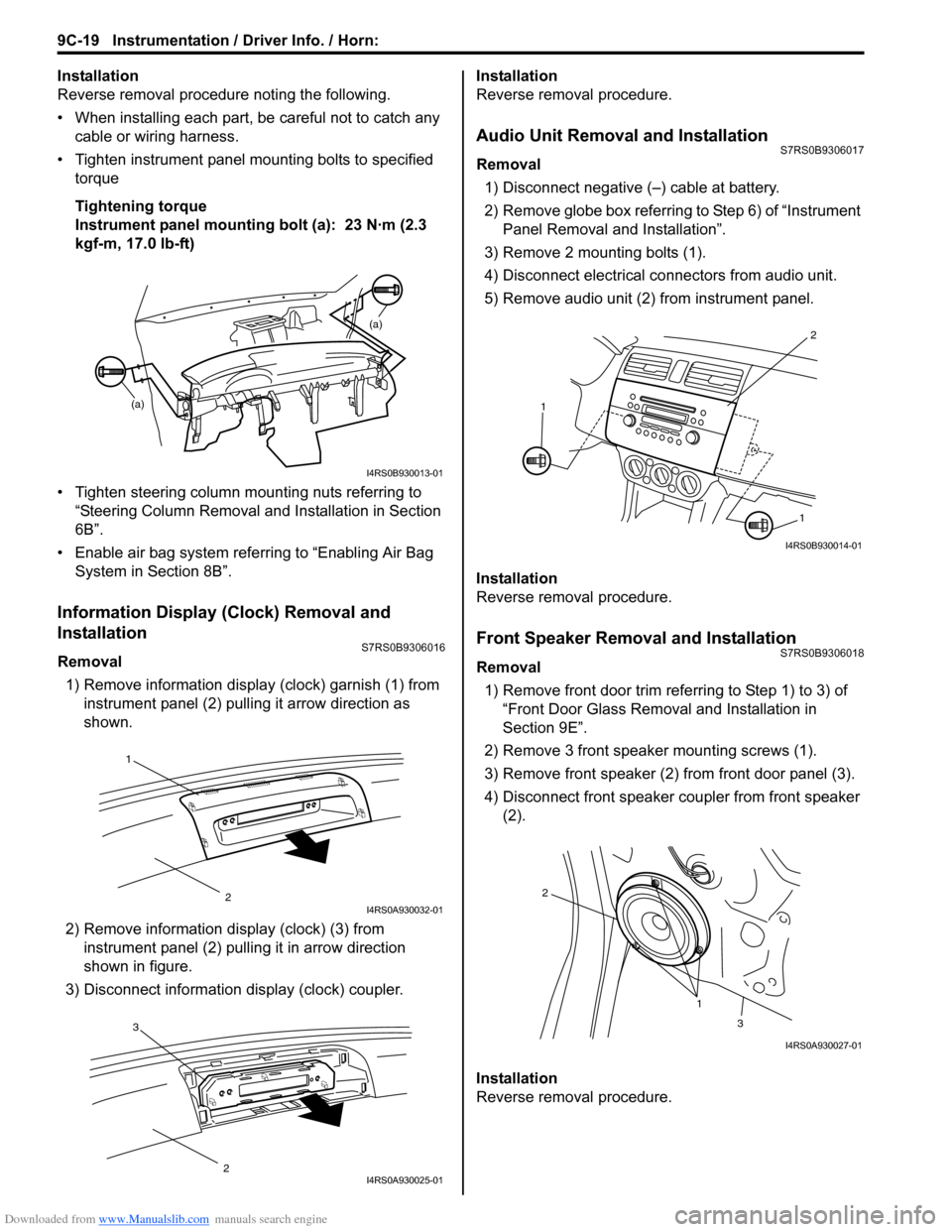
1) Remove information display (clock) garnish (1) from instrument panel (2) pulling it arrow direction as
shown.
2) Remove information di splay (clock) (3) from
instrument panel (2) pulli ng it in arrow direction
shown in figure.
3) Disconnect information display (clock) coupler. Installation
Reverse removal procedure.
Audio Unit Removal and InstallationS7RS0B9306017
Removal
1) Disconnect negative (–) cable at battery.
2) Remove globe box referring to Step 6) of “Instrument Panel Removal and Installation”.
3) Remove 2 mounting bolts (1).
4) Disconnect electrical connectors from audio unit.
5) Remove audio unit (2) from instrument panel.
Installation
Reverse removal procedure.
Front Speaker Removal and InstallationS7RS0B9306018
Removal 1) Remove front door trim refe rring to Step 1) to 3) of
“Front Door Glass Remo val and Installation in
Section 9E”.
2) Remove 3 front speaker mounting screws (1).
3) Remove front speaker (2) from front door panel (3).
4) Disconnect front speaker coupler from front speaker (2).
Installation
Reverse removal procedure.
(a) (a)
I4RS0B930013-01
1
2I4RS0A930032-01
3
2I4RS0A930025-01
2
1
1
I4RS0B930014-01
1
2
3
I4RS0A930027-01