Page 1360 of 1496
Downloaded from www.Manualslib.com manuals search engine 9F-14 Security and Locks:
Keyless Entry Answer Back Function Change-
over Procedure (If Equipped)
S7RS0B9606016
Output of keyless entry answer back function can be
switched over by performing the following procedure.
1) Confirm that all doors are closed, all doors are unlocked, ignition key is out of ignition key cylinder
and interior light switch is in the middle position.
2) Perform Step a) through c) described below within 10 seconds.
a) Insert ignition key in ignition key cylinder.
b) Remove ignition key from ignition key cylinder.
c) Repeat Step a) and b) once.
3) Push “UNLOCK” button on transmitter 3 times within 10 seconds.
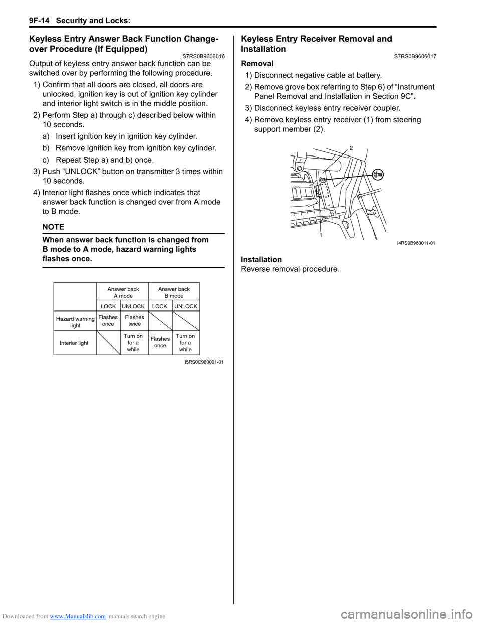
4) Interior light flashes once which indicates that answer back function is changed over from A mode
to B mode.
NOTE
When answer back function is changed from
B mode to A mode, hazard warning lights
flashes once.
Keyless Entry Receiver Removal and
Installation
S7RS0B9606017
Removal
1) Disconnect negative cable at battery.
2) Remove grove box referring to Step 6) of “Instrument Panel Removal and Installation in Section 9C”.
3) Disconnect keyless entry receiver coupler.
4) Remove keyless entry receiver (1) from steering support member (2).
Installation
Reverse removal procedure.
Hazard warning light
LOCK LOCK
UNLOCK UNLOCK
Interior lightFlashes
once Flashes
twice
Flashesonce
Turn on
for a
while Turn on
for a
while
Answer back
A mode Answer back
B mode
I5RS0C960001-01
1 2I4RS0B960011-01
Page 1364 of 1496
Downloaded from www.Manualslib.com manuals search engine 9G-2 Seats:
Front Seat Removal and InstallationS7RS0B9706002
WARNING!
Refer to “Air Bag Warning in Section 00” before starting service work.
Removal1) Disable air bag system referring to “Disabling Air Bag System in Section 8B”.
2) Disconnect couplers for seat harness and side air bag, if equipped.
3) Remove 4 mounting bolts to remove seat assembly.
4) Disassemble and repair seat if necessary.
Installation
Reverse removal procedure to install front seat.
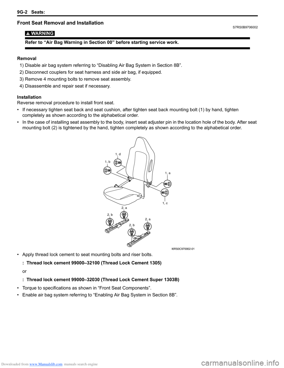
• If necessary tighten seat back and seat cushion, after tighten seat back mounting bolt (1) by hand, tighten completely as shown according to the alphabetical order.
• In the case of installing seat assembly to the body, insert se at adjuster pin in the location hole of the body. After seat
mounting bolt (2) is tightened by t he hand, tighten completely as shown according to the alphabetical order.
• Apply thread lock cement to seat mounting bolts and riser bolts. : Thread lock cement 99000–32100 (Thread Lock Cement 1305)
or
: Thread lock cement 99000–32030 (Thread Lock Cement Super 1303B)
• Torque to specifications as shown in “Front Seat Components”.
• Enable air bag system referring to “Enabling Air Bag System in Section 8B”.
1, d
1, b
1, a
1, c
2, a
2, b2, a
2, b
I6RS0C970002-01
Page 1372 of 1496
Downloaded from www.Manualslib.com manuals search engine 9J-3 Hood / Fenders / Doors:
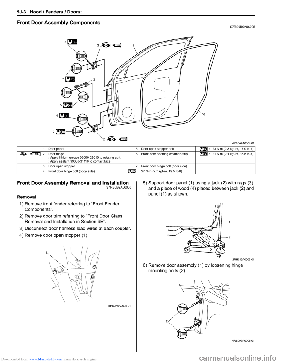
Front Door Assembly ComponentsS7RS0B9A06005
Front Door Assembly Removal and InstallationS7RS0B9A06006
Removal1) Remove front fender referring to “Front Fender Components”.
2) Remove door trim referring to “Front Door Glass Removal and Installa tion in Section 9E”.
3) Disconnect door harness lead wires at each coupler.
4) Remove door open stopper (1). 5) Support door panel (1) using a jack (2) with rags (3)
and a piece of wood (4) placed between jack (2) and
panel (1) as shown.
6) Remove door assembly (1) by loosening hinge mounting bolts (2).
2
21(a)4
(a)4
3(b)7
(b)7
(c)5
6
I4RS0A9A0004-01
1. Door panel 5. Door open stopper bolt: 23 N⋅m (2.3 kgf-m, 17.0 lb-ft)
2. Door hinge : Apply lithium grease 99000-25010 to rotating part.
: Apply sealant 99000-31110 to contact face. 6. Front door opening weather-strip
: 21 N⋅m (2.1 kgf-m, 15.5 lb-ft)
3. Door open stopper 7. Front door hinge bolt (door side)
4. Front door hinge bolt (body side) : 27 N⋅m (2.7 kgf-m, 19.5 lb-ft)
I4RS0A9A0005-01
I2RH019A0003-01
1
2
I4RS0A9A0006-01
Page 1375 of 1496
Downloaded from www.Manualslib.com manuals search engine Hood / Fenders / Doors: 9J-6
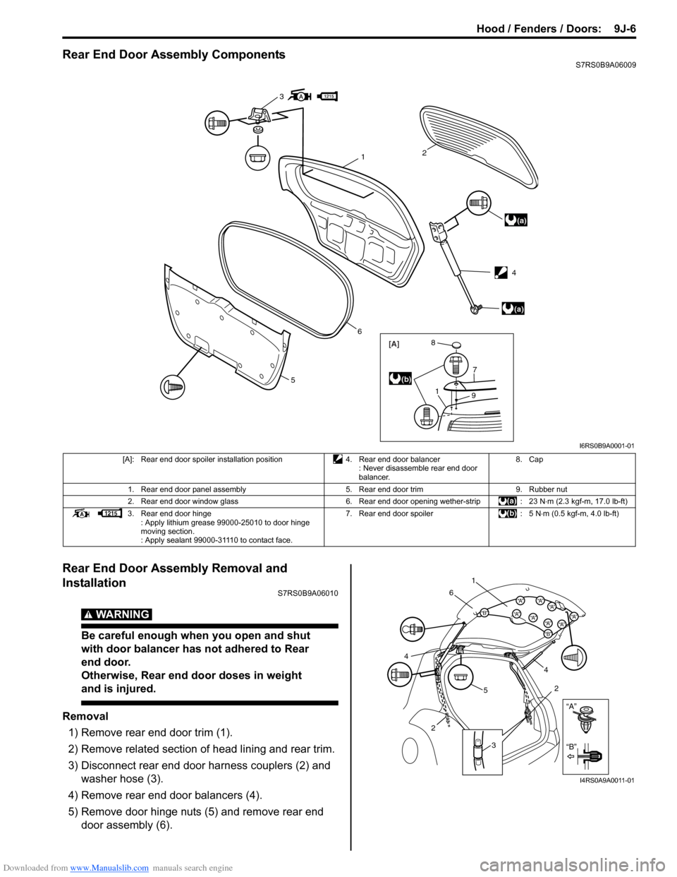
Rear End Door Assembly ComponentsS7RS0B9A06009
Rear End Door Assembly Removal and
Installation
S7RS0B9A06010
WARNING!
Be careful enough when you open and shut
with door balancer has not adhered to Rear
end door.
Otherwise, Rear end door doses in weight
and is injured.
Removal1) Remove rear end door trim (1).
2) Remove related section of head lining and rear trim.
3) Disconnect rear end door harness couplers (2) and washer hose (3).
4) Remove rear end door balancers (4).
5) Remove door hinge nuts (5) and remove rear end door assembly (6).
3
(a)
(a)
12
6
5
[A]
1
7
9
8
(b)
4
I6RS0B9A0001-01
[A]: Rear end door spoiler installation position 4. Rear end door balancer
: Never disassemble rear end door
balancer. 8. Cap
1. Rear end door panel assembly 5. Rear end door trim9. Rubber nut
2. Rear end door window glass 6. Rear end door opening wether-strip: 23 N⋅m (2.3 kgf-m, 17.0 lb-ft)
3. Rear end door hinge : Apply lithium grease 99000-25010 to door hinge
moving section.
: Apply sealant 99000-31110 to contact face. 7. Rear end door spoiler
: 5 N⋅m (0.5 kgf-m, 4.0 lb-ft)
“A”
“B”
“B”
“A”“B”“A”“A”“A”
“A”“A”“A”
“A”
1
6
5 4
2
3
2
4
I4RS0A9A0011-01
Page 1434 of 1496
Downloaded from www.Manualslib.com manuals search engine 10B-31 Body Electrical Control System:
Inspection of BCM and its CircuitsS7RS0BA204018
BCM and its circuits can be checked at BCM wiring couplers by measuring voltage and resistance.
CAUTION!
BCM cannot be checked by itself. It is strictly prohibited to connect voltmeter or ohmmeter to BCM
with couplers disconnected from it.
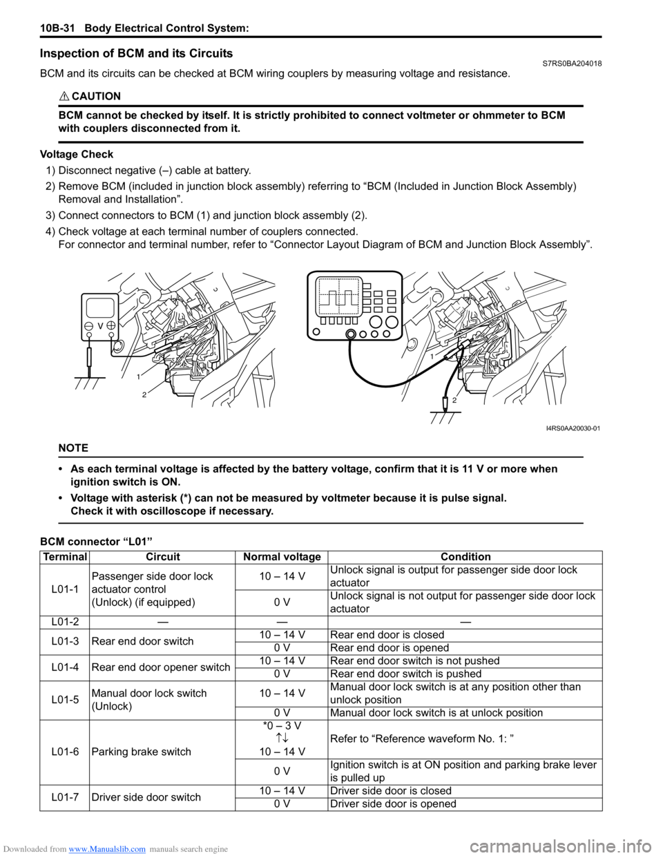
Voltage Check1) Disconnect negative (–) cable at battery.
2) Remove BCM (included in junction block assembly) refe rring to “BCM (Included in Junction Block Assembly)
Removal and Installation”.
3) Connect connectors to BCM (1) and junction block assembly (2).
4) Check voltage at each terminal number of couplers connected. For connector and terminal number, refer to “Connector Layout Diagram of BCM and Junction Block Assembly”.
NOTE
• As each terminal voltage is affected by the battery voltage, confirm that it is 11 V or more when
ignition switch is ON.
• Voltage with asterisk (*) can not be measured by voltmeter because it is pulse signal. Check it with oscilloscope if necessary.
BCM connector “L01”
1
2
1
2
I4RS0AA20030-01
Terminal CircuitNormal voltage Condition
L01-1 Passenger side door lock
actuator control
(Unlock) (if equipped) 10 – 14 V
Unlock signal is output fo
r passenger side door lock
actuator
0 V Unlock signal is not output for passenger side door lock
actuator
L01-2 — — —
L01-3 Rear end door switch 10 – 14 V Rear end door is closed
0 V Rear end door is opened
L01-4 Rear end door opener switch 10 – 14 V Rear end door switch is not pushed
0 V Rear end door switch is pushed
L01-5 Manual door lock switch
(Unlock) 10 – 14 V
Manual door lock switch is at any position other than
unlock position
0 V Manual door lock switch is at unlock position
L01-6 Parking brake switch *0 – 3 V
↑↓
10 – 14 V Refer to “Reference waveform No. 1: ”
0 V Ignition switch is at ON po
sition and parking brake lever
is pulled up
L01-7 Driver side door switch 10 – 14 V Driver side door is closed
0 V Driver side door is opened
Page 1476 of 1496
Downloaded from www.Manualslib.com manuals search engine 10E-14 Keyless Start System:
Door Lock Operation (Keyless Start System)S7RS0BA504012
1) Check that all door locks are released and all doors are closed.
2) With remote controller of which ID code is registered in keyless start control m odule carried with yourself,
check that pushing driver door, passenger door or
rear end door request switch once locks all doors.
3) Check that pushing request switch of driver door, passenger door or rear end door once releases all
door locks.
Inspection of Keyless Start Control Module and Its CircuitsS7RS0BA504013
Keyless start control module and its circuits can be che cked at keyless start control module wiring couplers by
measuring voltage and resistance.
CAUTION!
Keyless start control module cannot be checked by itself. It is strictly prohibited to connect voltmeter
or ohmmeter to keyless start control module with coupler disconnected from it.
Voltage Check
1) Disconnect negative (–) cable at battery.
2) Remove keyless start control module from vehicle body referring to “Keyless Start Control Module Removal and
Installation”.
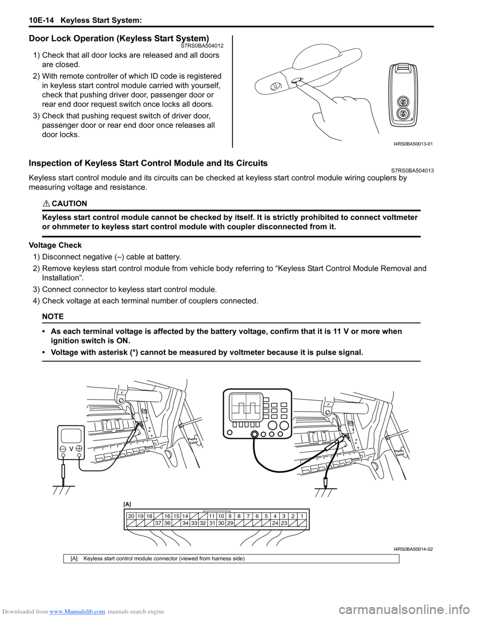
3) Connect connector to keyless start control module.
4) Check voltage at each terminal number of couplers connected.
NOTE
• As each terminal voltage is affected by the battery voltage, confirm that it is 11 V or more when ignition switch is ON.
• Voltage with asterisk (*) cannot be measured by voltmeter because it is pulse signal.
I4RS0BA50013-01
1234567891011
141516
36 34 33 32 31 30 29 24 23
37
181920
[A]
I4RS0BA50014-02
[A]: Keyless start control module connector (viewed from harness side)