2006 SUZUKI SWIFT Engine assembly
[x] Cancel search: Engine assemblyPage 1294 of 1496
Downloaded from www.Manualslib.com manuals search engine 9B-12 Lighting Systems:
Front Fog Light Aiming Adjustment with Screen
(If Equipped)
S7RS0B9206018
Basic Aiming
NOTE
• Unless otherwise obligated by local regulations, adjust front fog light aiming
according to the following procedure.
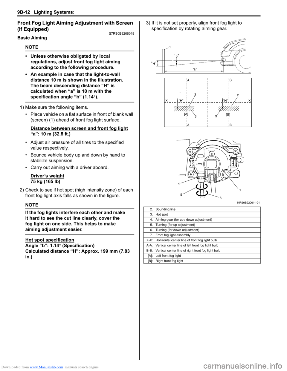
• An example in case that the light-to-wall distance 10 m is shown in the illustration.
The beam descending distance “H” is
calculated when “a” is 10 m with the
specification angle “b” (1.14 °).
1) Make sure the following items.
• Place vehicle on a flat surface in front of blank wall (screen) (1) ahead of front fog light surface.
Distance between screen and front fog light
“a”: 10 m (32.8 ft.)
• Adjust air pressure of all tires to the specified value respectively.
• Bounce vehicle body up and down by hand to stabilize suspension.
• Carry out aiming with a driver aboard.
Driver’s weight
75 kg (165 lb)
2) Check to see if hot spot (h igh intensity zone) of each
front fog light axis falls as shown in the figure.
NOTE
If the fog lights interfere each other and make
it hard to see the cut line clearly, cover the
fog light on one side. This helps to make
aiming adjustment easier.
Hot spot specification
Angle “b”: 1.14° (Specification)
Calculated distance “H”: Approx. 199 mm (7.83
in.) 3) If it is not set properly
, align front fog light to
specification by rotating aiming gear.
2. Bounding line
3. Hot spot
4. Aiming gear (for up / down adjustment)
5. Turning (for up adjustment)
6. Turning (for down adjustment)
7. Front fog light assembly
X-X: Horizontal center line of front fog light bulb
A-A: Vertical center line of left front fog light bulb
B-B: Vertical center line of right front fog light bulb [A]: Left front fog light
[B]: Right front fog light
I4RS0B920011-01
Page 1301 of 1496
Downloaded from www.Manualslib.com manuals search engine Instrumentation / Driver Info. / Horn: 9C-6
Component Location
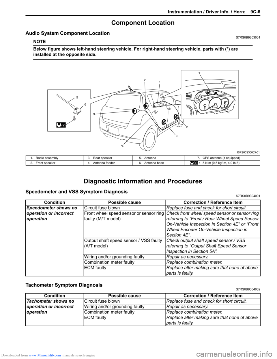
Audio System Component LocationS7RS0B9303001
NOTE
Below figure shows left-hand steering vehicle. For right-hand steering vehicle, parts with (*) are
installed at the opposite side.
Diagnostic Information and Procedures
Speedometer and VSS Symptom DiagnosisS7RS0B9304001
Tachometer Symptom DiagnosisS7RS0B9304002
6
5
(a)
7
1
2
2
3
3
*4
I6RS0C930003-01
1. Radio assembly
3. Rear speaker5. Antenna 7. GPS antenna (if equipped)
2. Front speaker 4. Antenna feeder6. Antenna base : 5 N⋅m (0.5 kgf-m, 4.0 lb-ft)
Condition Possible cause Correction / Reference Item
Speedometer shows no
operation or incorrect
operation Circuit fuse blown
Replace fuse and check for short circuit.
Front wheel speed sensor or sensor ring
faulty (M/T model) Check front wheel speed sensor or sensor ring
referring to “Front / Rear Wheel Speed Sensor
On-Vehicle Inspection in
Section 4E” or “Front
Wheel Encoder On-Vehicle Inspection in
Section 4E”.
Output shaft speed sensor / VSS faulty
(A/T model) Check output shaft
speed sensor / VSS
referring to “Output Shaft Speed Sensor
Inspection in Section 5A”.
Wiring and/or grounding faulty Repair as necessary.
Combination meter faulty Replace combination meter.
ECM faulty Replace after making sure that none of above
parts is faulty.
ConditionPossible cause Correction / Reference Item
Tachometer shows no
operation or incorrect
operation Circuit fuse blown
Replace fuse and check for short circuit.
Wiring and/or grounding faulty Repair as necessary.
Combination meter faulty Replace combination meter.
ECM faulty Replace after making sure that none of above
parts is faulty.
Page 1307 of 1496
Downloaded from www.Manualslib.com manuals search engine Instrumentation / Driver Info. / Horn: 9C-12
Clock Symptom Diagnosis (If Equipped)S7RS0B9304016
Audio System Symptom Diagnosis (If Equipped)S7RS0B9304017
Radio
NOTE
Electronic part / system with undiagnosed pr oblem may cause electromagnetic interference.
Electromagnetic interference condition may have poor radio reception. To test for presence of
electromagnetic interference in part / system, perform the following procedures.
1. Turn ignition switch to OFF.
2. Systematically disconnect the electronic part / system connector(s) one at a time.
3. Turn ignition switch to ON.
4. Check any improvement in radio reception.
Display of fuel
consumption does not
change at “– – – l / 100 km
(km/l, MPG)” Vehicle is not running (instantaneous
fuel consumption mode)
—
Fuel consumption was reset (average
fuel consumption mo de, if equipped)Vehicle runs for a while.
Vehicle speed signal faulty Check ECM for DTC referring to “DTC Check
in Section 1A”.
Wiring and/or grounding faulty Repair as necessary.
ECM faulty Check input and output signal of ECM referring
to “Inspection of ECM and Its Circuits in
Section 1A”.
Information display unit faulty Replace unit.
BCM faulty Replace after making sure that none of above
parts is faulty.
Condition Possible cause Correction / Reference Item
Condition
Possible cause Correction / Reference Item
No displaying of clock Circuit fuse Blown Replace fuse and check for short circuit.
Wiring and/or grounding faulty Repair as necessary.
Clock unit faulty Replace unit.
ConditionPossible cause Correction / Reference Item
Poor radio reception Out of service area (Poor location) —
Antenna faulty Replace antenna.
Electrical part / system faulty Repair or replace electrical part / system
referring to after-mentioned NOTE.
Wiring and/or grounding faulty Repair as necessary.
Radio assembly faulty Replace radio assembly.
Radio does not operate
and speaker does not
sound Circuit fuse(s) blown
Replace fuse(s) and check for short circuit.
Wiring and/or grounding faulty Repair as necessary.
Radio assembly faulty Replace radio assembly.
Radio does not operate,
but speaker sound Wiring and/or grounding faulty
Repair as necessary.
Radio assembly faulty Replace radio assembly.
Radio is operative, but all
speakers does not sound Wiring and/or grounding faulty
Repair as necessary.
Radio assembly faulty Replace radio assembly.
Individual speaker is
noisy or inoperative Wiring and/or grounding faulty
Repair as necessary.
Speaker faulty Replace speaker.
Radio assembly faulty Replace radio assembly.
Sound quality is poor Out of service area (Poor location) —
Speaker installed incorrectly Install correctly.
Wiring and/or grounding faulty Repair as necessary.
Speaker faulty Replace speaker.
Radio assembly faulty Replace radio assembly.
Page 1308 of 1496
Downloaded from www.Manualslib.com manuals search engine 9C-13 Instrumentation / Driver Info. / Horn:
CD Player
Auto Volume Control System
Remote Audio Control Switch Symptom Diagnosis (If Equipped)S7RS0B9304018
ConditionPossible cause Correction / Reference Item
CD-ROM does not insert Another CD-ROM already inserted Eject CD-ROM.
Circuit fuse blown Replace fuse and check for short circuit.
Wiring and/or grounding faulty Repair as necessary.
Extraneous material come to be mixed
CD player Clear extraneous material from CD player or
replace radio assembly.
Radio assembly faulty Replace radio assembly.
CD-ROM does not eject Circuit fuse blown Replace fuse and check for short circuit.
Wiring and/or grounding faulty Repair as necessary.
Extraneous material come to be mixed
in CD player Clear extraneous material from CD player or
replace radio assembly.
Radio assembly faulty Replace radio assembly.
CD player does not load
CD-ROM CD-ROM faulty
—
CD-ROM inserted wit h incorrect side upInsert correctly.
Temperature in cabin is too hot —
Water droplets form on internal lens Dry about 1 hour with power on.
Radio assembly faulty Replace radio assembly.
Sound skips or is noisy CD-ROM faulty —
Driving vibration —
Water droplets form on internal lens Dry about 1 hour with power on.
Radio assembly installed incorrectly Install correctly.
Radio assembly faulty Replace radio assembly.
CD player is operative,
but all speakers does not
sound Wiring and/or grounding faulty
Repair as necessary.
Radio assembly faulty Replace radio assembly.
Individual speaker is
noisy or inoperative Wiring and/or grounding faulty
Repair as necessary.
Speaker faulty Replace speaker.
Radio assembly faulty Replace radio assembly.
Sound quality or volume
is poor CD-ROM faulty
—
Wiring and/or grounding faulty Repair as necessary.
Speaker installed incorrectly Install correctly.
Speaker faulty Replace speaker.
ConditionPossible cause Correction / Reference Item
Sound volume does not
vary according to
changes of vehicle speed Auto volume control system is “OFF”
mode
Select auto volume control.
Vehicle speed signal faulty Check vehicle speed signal referring to
“Vehicle Speed Signal Inspection (For Audio
Unit) (If Equipped)”.
Wiring and/or grounding faulty Repair as necessary.
ECM faulty Check input and output signal of ECM referring
to “Inspection of ECM and Its Circuits in
Section 1A”
Radio assembly faulty Replace radio assembly.
ConditionPossible cause Correction / Reference Item
Audio system is
operative, but remote
control switch does not
control audio system Remote audio control switch faulty
Check remote audio control switch referring to
“Remote Audio Control Switch Inspection (If
Equipped)”.
Contact coil faulty Replace contact coil.
Wiring and/or grounding faulty Repair as necessary.
Radio assembly faulty Replace radio assembly.
Page 1315 of 1496
Downloaded from www.Manualslib.com manuals search engine Instrumentation / Driver Info. / Horn: 9C-20
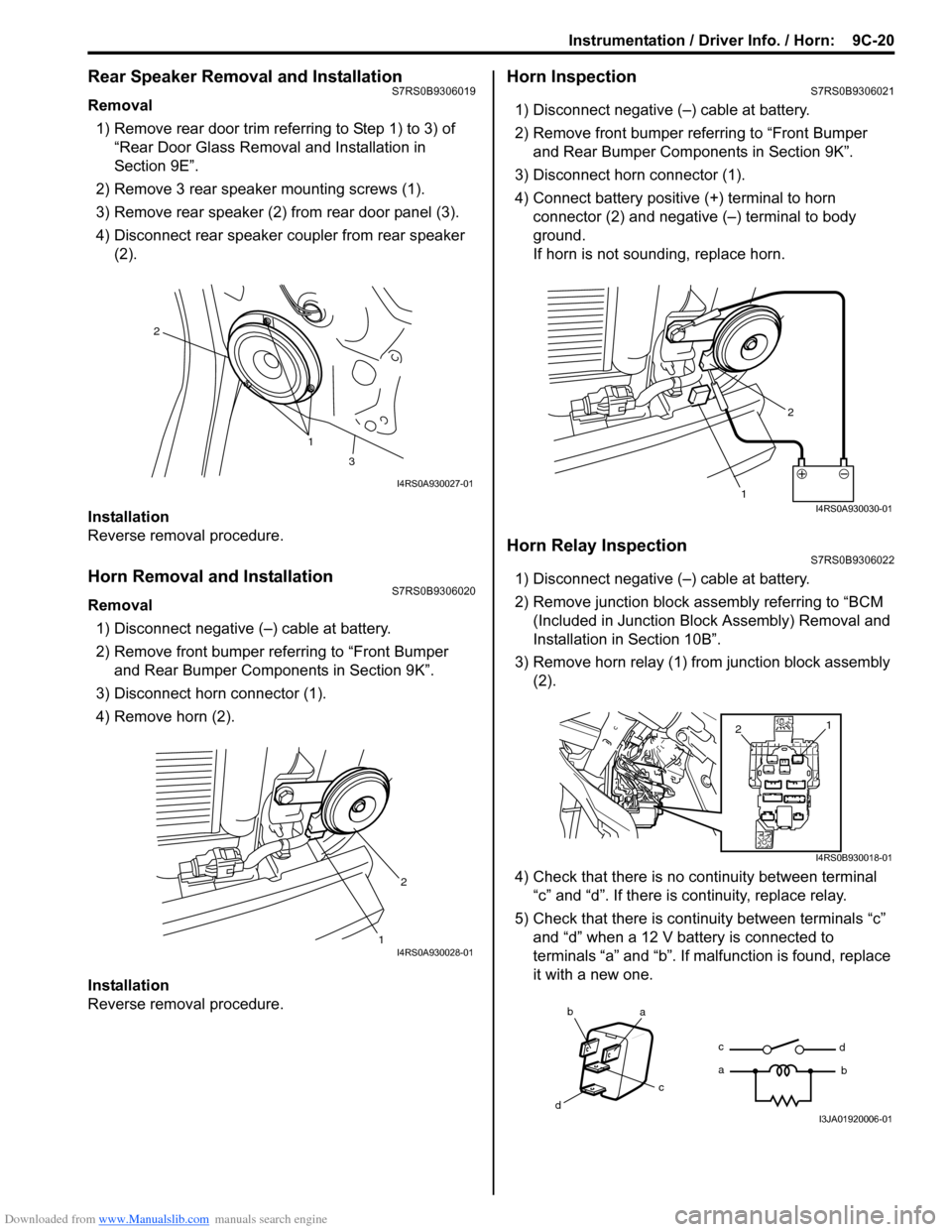
Rear Speaker Removal and InstallationS7RS0B9306019
Removal
1) Remove rear door trim referring to Step 1) to 3) of “Rear Door Glass Removal and Installation in
Section 9E”.
2) Remove 3 rear speaker mounting screws (1).
3) Remove rear speaker (2) from rear door panel (3).
4) Disconnect rear speaker coupler from rear speaker (2).
Installation
Reverse removal procedure.
Horn Removal and InstallationS7RS0B9306020
Removal 1) Disconnect negative (–) cable at battery.
2) Remove front bumper referring to “Front Bumper and Rear Bumper Components in Section 9K”.
3) Disconnect horn connector (1).
4) Remove horn (2).
Installation
Reverse removal procedure.
Horn InspectionS7RS0B9306021
1) Disconnect negative (–) cable at battery.
2) Remove front bumper referring to “Front Bumper and Rear Bumper Components in Section 9K”.
3) Disconnect horn connector (1).
4) Connect battery positive (+) terminal to horn
connector (2) and negative (–) terminal to body
ground.
If horn is not sounding, replace horn.
Horn Relay InspectionS7RS0B9306022
1) Disconnect negative (–) cable at battery.
2) Remove junction block assembly referring to “BCM (Included in Junction Bl ock Assembly) Removal and
Installation in Section 10B”.
3) Remove horn relay (1) from junction block assembly (2).
4) Check that there is no continuity between terminal “c” and “d”. If there is continuity, replace relay.
5) Check that there is continuity between terminals “c” and “d” when a 12 V battery is connected to
terminals “a” and “b”. If malfunction is found, replace
it with a new one.
1
2
3
I4RS0A930027-01
12I4RS0A930028-01
1 2I4RS0A930030-01
1
2
I4RS0B930018-01
ba
c
d c
a
d
bI3JA01920006-01
Page 1320 of 1496
Downloaded from www.Manualslib.com manuals search engine 9D-3 Wipers / Washers:
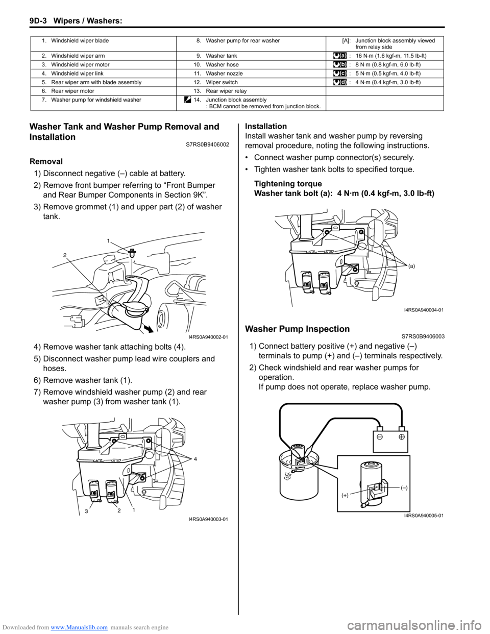
Washer Tank and Washer Pump Removal and
Installation
S7RS0B9406002
Removal1) Disconnect negative (–) cable at battery.
2) Remove front bumper referring to “Front Bumper and Rear Bumper Components in Section 9K”.
3) Remove grommet (1) and upper part (2) of washer tank.
4) Remove washer tank attaching bolts (4).
5) Disconnect washer pump lead wire couplers and hoses.
6) Remove washer tank (1).
7) Remove windshield washer pump (2) and rear washer pump (3) from washer tank (1). Installation
Install washer tank and washer pump by reversing
removal procedure, noting the following instructions.
• Connect washer pump connector(s) securely.
• Tighten washer tank bolts to specified torque.
Tightening torque
Washer tank bolt (a): 4 N·m (0.4 kgf-m, 3.0 lb-ft)
Washer Pump InspectionS7RS0B9406003
1) Connect battery positive (+) and negative (–) terminals to pump (+) and (–) terminals respectively.
2) Check windshield and rear washer pumps for
operation.
If pump does not operate, replace washer pump.
1. Windshield wiper blade 8. Washer pump for rear washer[A]: Junction block assembly viewed
from relay side
2. Windshield wiper arm 9. Washer tank: 16 N⋅m (1.6 kgf-m, 11.5 lb-ft)
3. Windshield wiper motor 10. Washer hose : 8 N⋅m (0.8 kgf-m, 6.0 lb-ft)
4. Windshield wiper link 11. Washer nozzle : 5 N⋅m (0.5 kgf-m, 4.0 lb-ft)
5. Rear wiper arm with blade assembly 12. Wiper switch : 4 N⋅m (0.4 kgf-m, 3.0 lb-ft)
6. Rear wiper motor 13. Rear wiper relay
7. Washer pump for windshield washer 14. Junction block assembly
: BCM cannot be removed from junction block.
1
2
I4RS0A940002-01
2 1 4
3
I4RS0A940003-01
(a)
I4RS0A940004-01
(–)
(+)
I4RS0A940005-01
Page 1321 of 1496
Downloaded from www.Manualslib.com manuals search engine Wipers / Washers: 9D-4
Windshield Wiper Removal and InstallationS7RS0B9406004
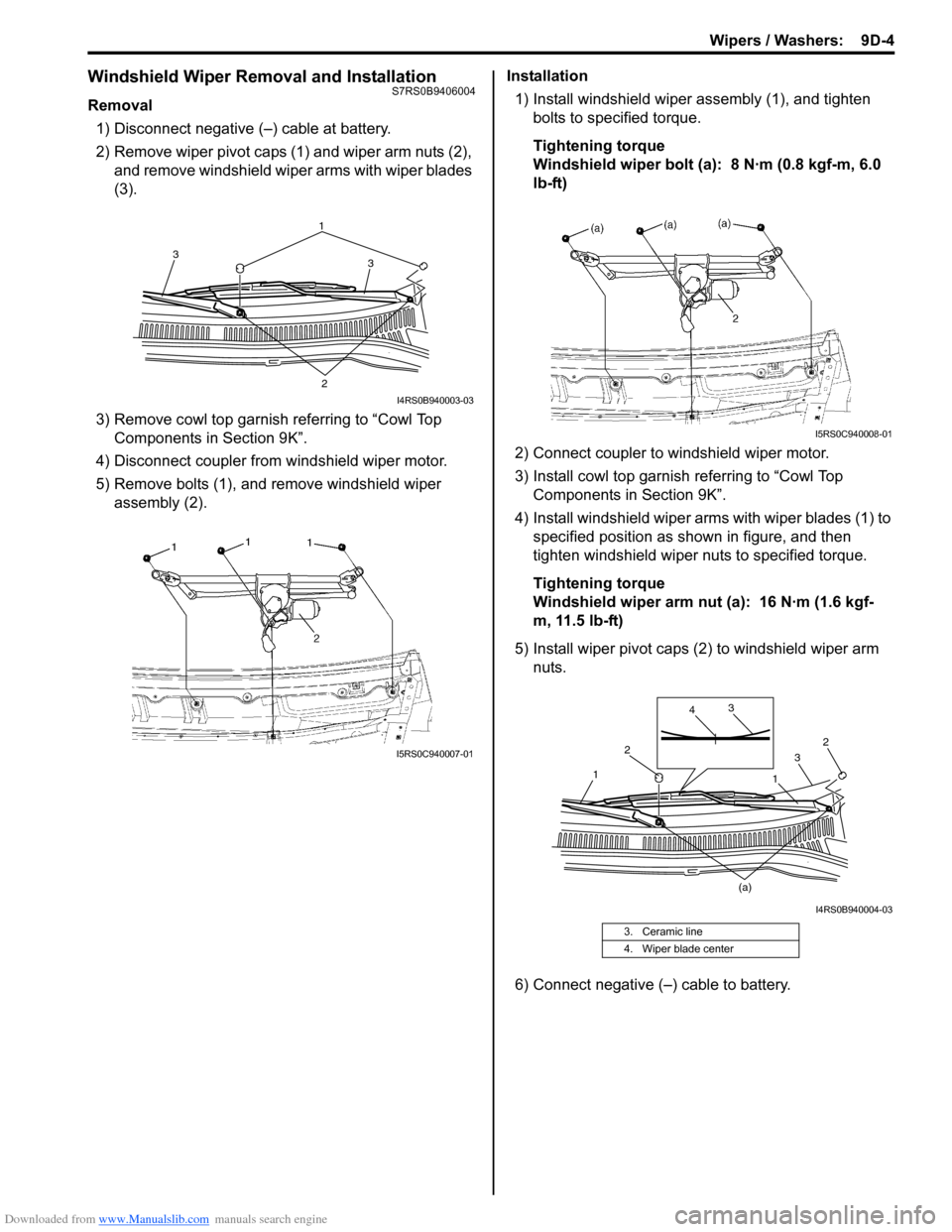
Removal1) Disconnect negative (–) cable at battery.
2) Remove wiper pivot caps (1) and wiper arm nuts (2), and remove windshield wiper arms with wiper blades
(3).
3) Remove cowl top garnish referring to “Cowl Top Components in Section 9K”.
4) Disconnect coupler from windshield wiper motor.
5) Remove bolts (1), and remove windshield wiper assembly (2). Installation
1) Install windshield wiper assembly (1), and tighten bolts to specified torque.
Tightening torque
Windshield wiper bolt (a): 8 N·m (0.8 kgf-m, 6.0
lb-ft)
2) Connect coupler to windshield wiper motor.
3) Install cowl top garnish referring to “Cowl Top
Components in Section 9K”.
4) Install windshield wiper arms with wiper blades (1) to specified position as shown in figure, and then
tighten windshield wiper nuts to specified torque.
Tightening torque
Windshield wiper arm nut (a): 16 N·m (1.6 kgf-
m, 11.5 lb-ft)
5) Install wiper pivot caps (2 ) to windshield wiper arm
nuts.
6) Connect negative (–) cable to battery.
1 3
3
2
I4RS0B940003-03
I5RS0C940007-01
3. Ceramic line
4. Wiper blade center
I5RS0C940008-01
2
2 3
3
4
1
1
(a)
I4RS0B940004-03
Page 1323 of 1496
Downloaded from www.Manualslib.com manuals search engine Wipers / Washers: 9D-6
Rear Wiper Removal and InstallationS7RS0B9406006
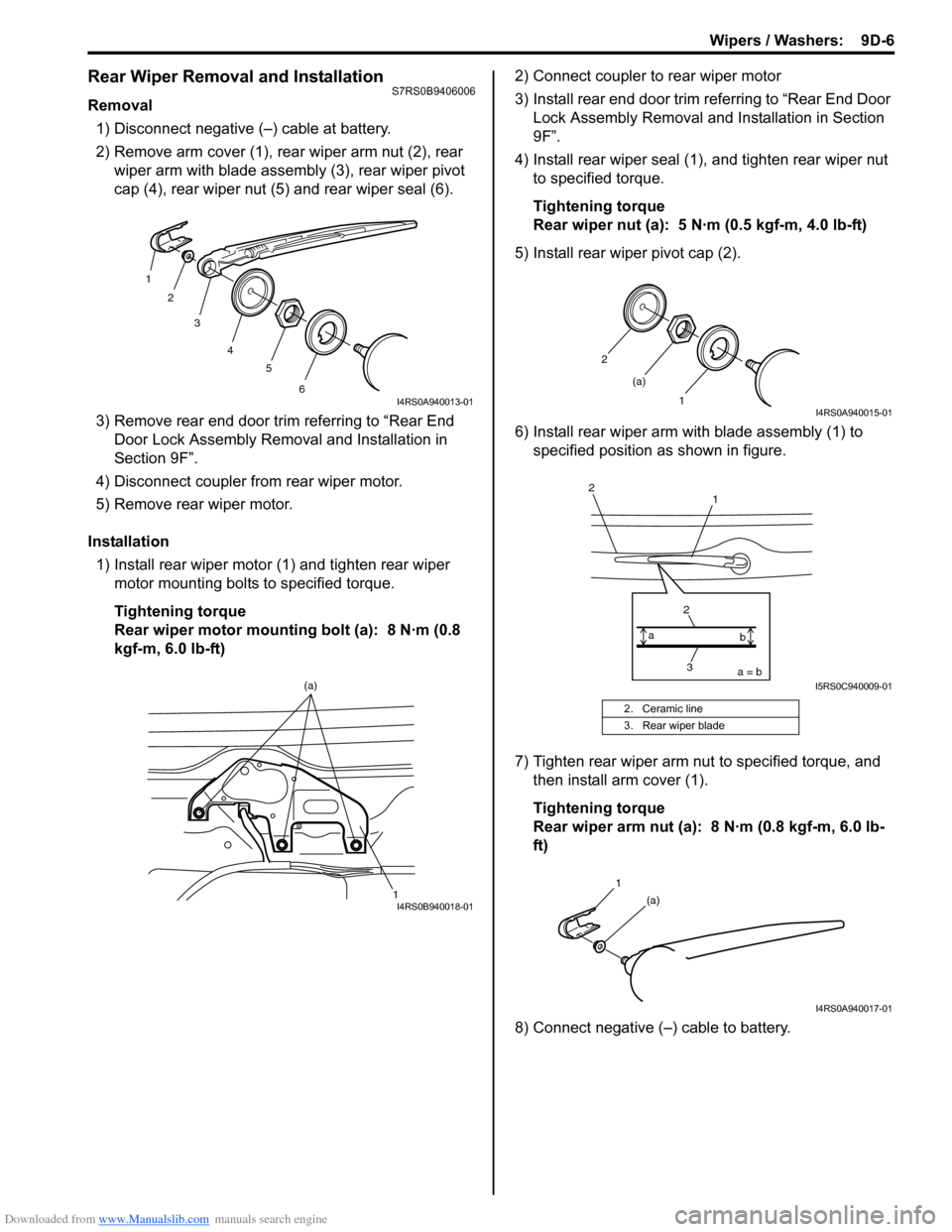
Removal1) Disconnect negative (–) cable at battery.
2) Remove arm cover (1), rear wiper arm nut (2), rear wiper arm with blade assembly (3), rear wiper pivot
cap (4), rear wiper nut (5) and rear wiper seal (6).
3) Remove rear end door trim referring to “Rear End Door Lock Assembly Remo val and Installation in
Section 9F”.
4) Disconnect coupler from rear wiper motor.
5) Remove rear wiper motor.
Installation 1) Install rear wiper motor (1) and tighten rear wiper motor mounting bolts to specified torque.
Tightening torque
Rear wiper motor mounting bolt (a): 8 N·m (0.8
kgf-m, 6.0 lb-ft) 2) Connect coupler to rear wiper motor
3) Install rear end door trim referring to “Rear End Door
Lock Assembly Removal and Installation in Section
9F”.
4) Install rear wiper seal (1), and tighten rear wiper nut to specified torque.
Tightening torque
Rear wiper nut (a): 5 N·m (0.5 kgf-m, 4.0 lb-ft)
5) Install rear wiper pivot cap (2).
6) Install rear wiper arm with blade assembly (1) to specified position as shown in figure.
7) Tighten rear wiper arm nut to specified torque, and then install arm cover (1).
Tightening torque
Rear wiper arm nut (a): 8 N·m (0.8 kgf-m, 6.0 lb-
ft)
8) Connect negative (–) cable to battery.
1 2
3
4 5
6
I4RS0A940013-01
1
(a)I4RS0B940018-01
2. Ceramic line
3. Rear wiper blade
2
1
(a)
I4RS0A940015-01
1
2
3
2a = b
a
bI5RS0C940009-01
1
(a)
I4RS0A940017-01