2006 SUZUKI SWIFT range
[x] Cancel search: rangePage 205 of 1496
Downloaded from www.Manualslib.com manuals search engine Engine General Information and Diagnosis: 1A-155
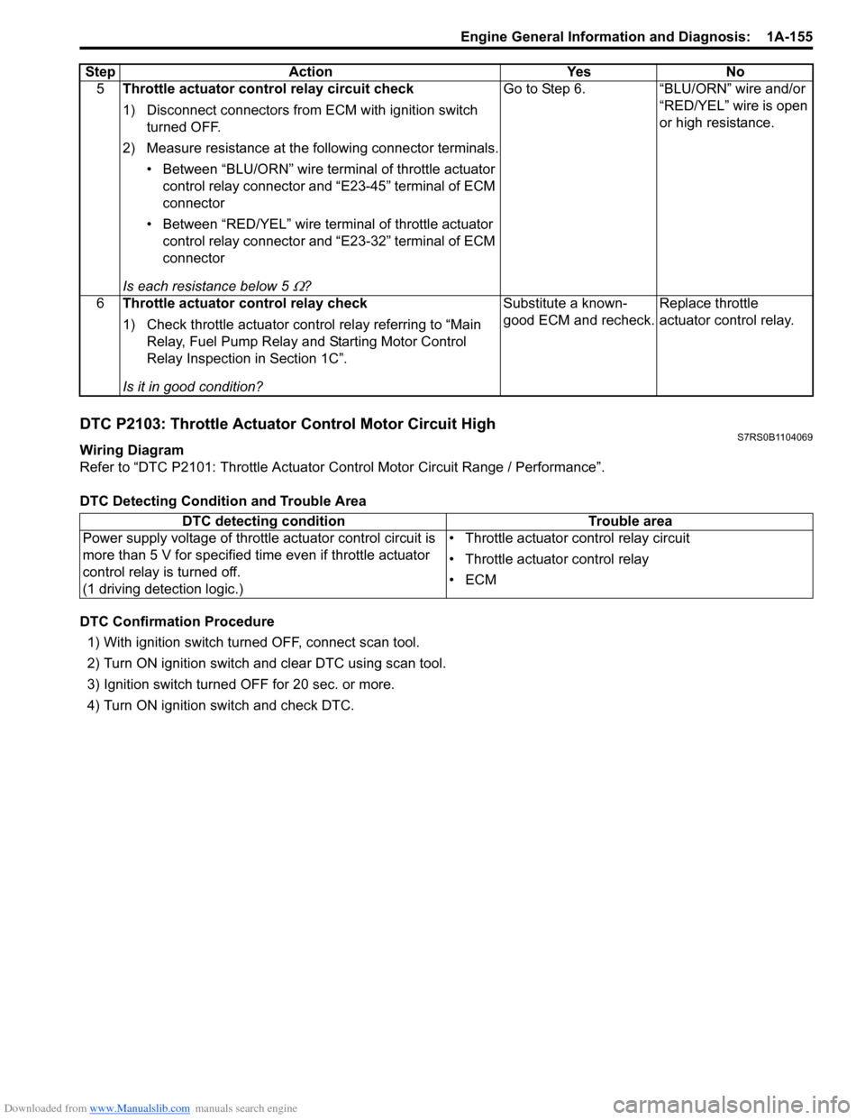
DTC P2103: Throttle Actuator Control Motor Circuit HighS7RS0B1104069
Wiring Diagram
Refer to “DTC P2101: Throttle Actuator Control Motor Circuit Range / Performance”.
DTC Detecting Condition and Trouble Area
DTC Confirmation Procedure 1) With ignition switch turned OFF, connect scan tool.
2) Turn ON ignition switch and clear DTC using scan tool.
3) Ignition switch turned OFF for 20 sec. or more.
4) Turn ON ignition switch and check DTC. 5
Throttle actuator cont rol relay circuit check
1) Disconnect connectors from ECM with ignition switch turned OFF.
2) Measure resistance at the following connector terminals. • Between “BLU/ORN” wire termin al of throttle actuator
control relay connector and “E23-45” terminal of ECM
connector
• Between “RED/YEL” wire terminal of throttle actuator control relay connector and “E23-32” terminal of ECM
connector
Is each resistance below 5
Ω? Go to Step 6. “BLU/ORN” wire and/or
“RED/YEL” wire is open
or high resistance.
6 Throttle actuator control relay check
1) Check throttle actuator control relay referring to “Main Relay, Fuel Pump Relay an d Starting Motor Control
Relay Inspection in Section 1C”.
Is it in good condition? Substitute a known-
good ECM and recheck.
Replace throttle
actuator control relay.
Step
Action YesNo
DTC detecting condition Trouble area
Power supply voltage of throttle actuator control circuit is
more than 5 V for specified time even if throttle actuator
control relay is turned off.
(1 driving detection logic.) • Throttle actuator control relay circuit
• Throttle actuator control relay
•ECM
Page 207 of 1496

Downloaded from www.Manualslib.com manuals search engine Engine General Information and Diagnosis: 1A-157
DTC Troubleshooting
NOTE
• When measuring circuit voltage, resistance and/or pulse signal at ECM connector, connect the
special tool to ECM and/or the ECM connectors re ferring to “Inspection of ECM and Its Circuits”.
• Upon completion of inspection and repair work, perform “DTC Confirmation Procedure” and confirm that the trouble has been corrected.
DTC P2119: Throttle Actuator Control Throttle Body Range / PerformanceS7RS0B1104071
Wiring Diagram
Refer to “DTC P2101: Throttle Actuator Control Motor Circuit Range / Performance”.
DTC Detecting Condition and Trouble Area Step Action Yes No
1 Was “Engine and Emission Control System Check”
performed? Go to Step 2. Go to Step “Engine and
Emission Control
System Check”.
2 Throttle valve visual check
1) Check that there isn’t any foreign matter caught between
throttle valve and throttle body housing referring to
“Throttle Valve Visual Check” under “Electric Throttle
Body Assembly On-Vehicle Inspection in Section 1C”.
Is it in good condition? Go to Step 3. Take it out after
removing throttle body
and clean inside of
throttle body thoroughly.
3 Throttle valve operation check
1) Check operation of throttle valve referring to “Throttle
Valve Operation Check” under “Electric Throttle Body
Assembly On-Vehicle Inspection in Section 1C”.
Is check result satisfactory? Go to Step 4. Replace electric throttle
body.
4 Throttle actuator operation check
1) Check operation of throttle ac tuator referring to “Throttle
Actuator Operation Check” under “Electric Throttle Body
Assembly On-Vehicle Inspection in Section 1C”.
Is check result satisfactory? Go to Step 5. Replace electric throttle
body.
5 Throttle position sensor performance check
1) Check performance of throttle position sensor referring
to “Throttle Position Sensor Performance Check” under
“Electric Throttle Body Assembly On-Vehicle Inspection
in Section 1C”.
Is check result satisfactory? Substitute a known-
good ECM and recheck.
Replace electric throttle
body.
DTC detecting condition
Trouble area
Difference between the measured (actual) throttle valve
opening angle and the target throttle valve opening angle
which is calculated based on accelerator pedal opening
angle and engine condition is more than specification for
specified time continuously.
(1 driving detection logic) • Throttle actuator circuit
• Electric throttle body
•ECM
Page 223 of 1496

Downloaded from www.Manualslib.com manuals search engine Engine General Information and Diagnosis: 1A-173
DTC P2227 / P2228 / P2229: Barometric Pressure Circuit MalfunctionS7RS0B1104078
DTC P2227: Barometric Pressure Circuit Range / Performance
DTC P2228: Barometric Pressure Circuit Low
DTC P2229: Barometric Pressure Circuit High
System Description
Barometric pressure sensor is installed in ECM.
DTC Detecting Condition and Trouble Area6
Wire harness check
1) Disconnect connectors from ECM with ignition switch
turned OFF.
2) Check for proper connection of ECM connector at “E23- 37”, “E23-52”, “E23-36” and “E23-51” terminals.
3) If OK, measure resistance between “GRN” wire terminal of APP sensor connector and vehicle body ground,
between “YEL” wire terminal of APP sensor connector
and vehicle body ground.
Is each resistance infinity? Go to Step 7. “GRN” wire or “YEL”
wire is shorted to other
circuit.
7 Wire harness check
1) Turn ON ignition switch.
2) Measure voltage between “E23-37” terminal of ECM
connector and engine ground, between “E23-36”
terminal of ECM connector and engine ground.
Is each voltage 0 V? Go to Step 8. “GRN” wire or “YEL”
wire is shorted to other
circuit.
8 APP sensor check
1) Check APP sensor referring to “APP Sensor Assembly
Inspection in Section 1C”.
Is output voltage within specified value? Substitute a known-
good ECM and recheck.
Replace APP sensor
assembly.
Step Action Yes No
DTC detecting condition
Trouble area
DTC P2227:
Difference of barometric pressure value and intake manifold
pressure value is higher than specified value while engine
cranking.
(*2 driving cycle detection logic, monitoring once par driving cycle) • Manifold absolute pressure sensor
performance problem
• Barometric pressure sensor in ECM
DTC P2228:
Barometric pressure signal less than specified value is detected.
(1 driving cycle detection logic) • Barometric pressure sensor in ECM
DTC P2229:
Barometric pressure signal more than specified value is detected.
(1 driving cycle detection logic)
Page 237 of 1496
Downloaded from www.Manualslib.com manuals search engine Engine General Information and Diagnosis: 1A-187
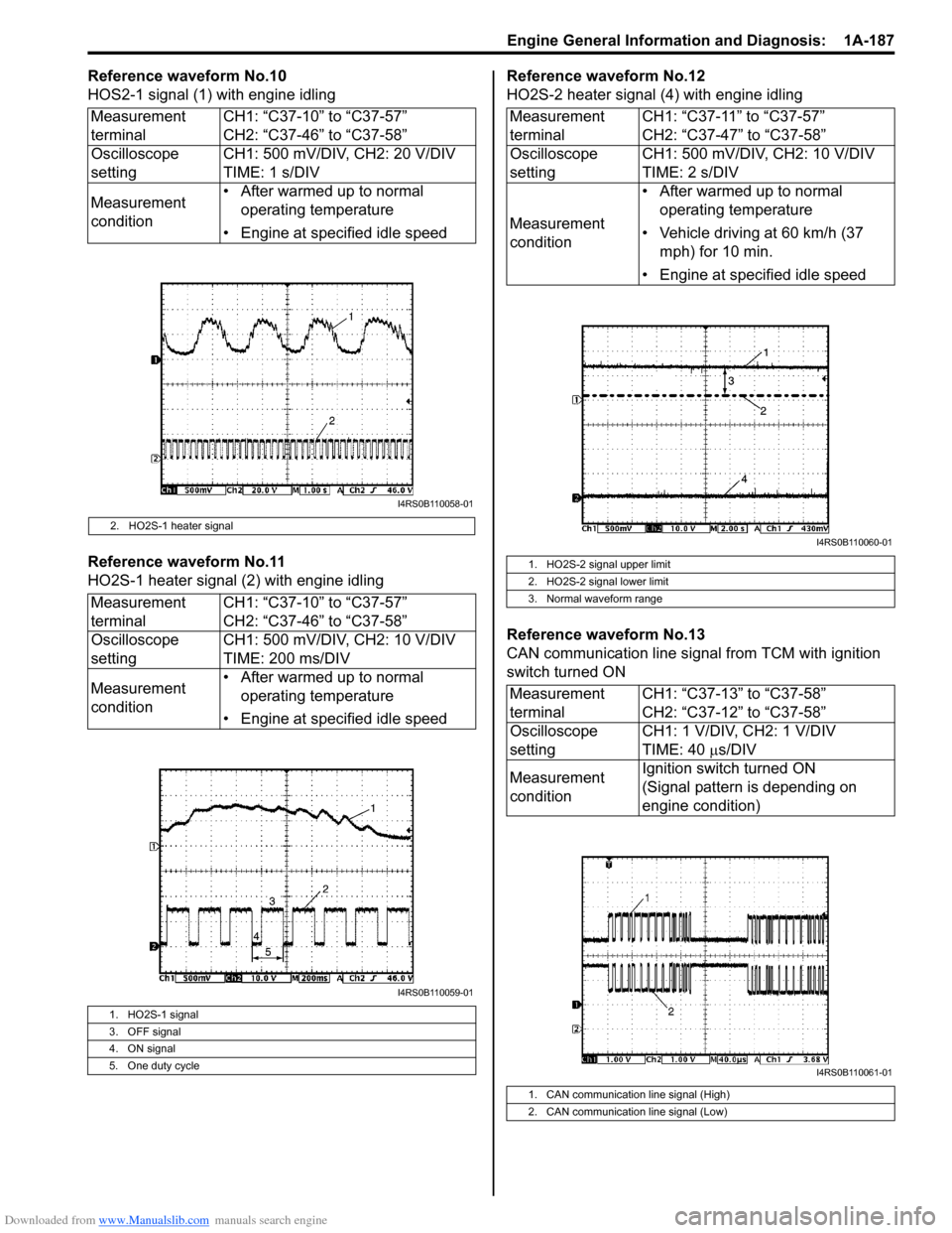
Reference waveform No.10
HOS2-1 signal (1) with engine idling
Reference waveform No.11
HO2S-1 heater signal (2) with engine idlingReference waveform No.12
HO2S-2 heater signal (4) with engine idling
Reference waveform No.13
CAN communication line signal from TCM with ignition
switch turned ON
Measurement
terminal
CH1: “C37-10” to “C37-57”
CH2: “C37-46” to “C37-58”
Oscilloscope
setting CH1: 500 mV/DIV, CH2: 20 V/DIV
TIME: 1 s/DIV
Measurement
condition • After warmed up to normal
operating temperature
• Engine at specified idle speed
2. HO2S-1 heater signal
Measurement
terminal CH1: “C37-10” to “C37-57”
CH2: “C37-46” to “C37-58”
Oscilloscope
setting CH1: 500 mV/DIV, CH2: 10 V/DIV
TIME: 200 ms/DIV
Measurement
condition • After warmed up to normal
operating temperature
• Engine at specified idle speed
1. HO2S-1 signal
3. OFF signal
4. ON signal
5. One duty cycle
I4RS0B110058-01
I4RS0B110059-01
Measurement
terminal CH1: “C37-11” to “C37-57”
CH2: “C37-47” to “C37-58”
Oscilloscope
setting CH1: 500 mV/DIV, CH2: 10 V/DIV
TIME: 2 s/DIV
Measurement
condition • After warmed up to normal
operating temperature
• Vehicle driving at 60 km/h (37 mph) for 10 min.
• Engine at specified idle speed
1. HO2S-2 signal upper limit
2. HO2S-2 signal lower limit
3. Normal waveform range
Measurement
terminal CH1: “C37-13” to “C37-58”
CH2: “C37-12” to “C37-58”
Oscilloscope
setting CH1: 1 V/DIV, CH2: 1 V/DIV
TIME: 40
µs/DIV
Measurement
condition Ignition switch turned ON
(Signal pattern is depending on
engine condition)
1. CAN communication line signal (High)
2. CAN communication line signal (Low)
I4RS0B110060-01
I4RS0B110061-01
Page 266 of 1496
Downloaded from www.Manualslib.com manuals search engine 1A-216 Engine General Information and Diagnosis:
Repair Instructions
Idle Speed and IAC Throttle Valve Opening
Inspection
S7RS0B1106001
Before idle speed check, make sure of the following.
• Lead wires and hoses of electronic fuel injection and engine and emission control systems are connected
securely.
• Valve lash is checked according to maintenance schedule.
• Ignition timing is within specification.
• All accessories (wipers, heater, lights, A/C, etc.) are out of service.
• Air cleaner has been properly installed and is in good condition.
• No abnormal air drawn in from air intake system.
After all items are confirmed, check idle speed and IAC
duty as follows.
NOTE
Before starting engine, place transmission
gear shift lever in “Neutral” (shift selector
lever to “P” range for A/T vehicle), and set
parking brake and block drive wheels.
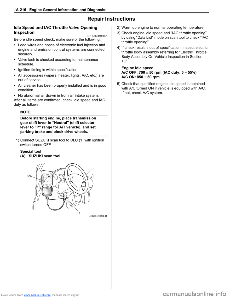
1) Connect SUZUKI scan tool to DLC (1) with ignition
switch turned OFF.
Special tool
(A): SUZUKI scan tool 2) Warm up engine to normal operating temperature.
3) Check engine idle speed and “IAC throttle opening”
by using “Data List” mode on scan tool to check “IAC
throttle opening”.
4) If check result is out of sp ecification, inspect electric
throttle body assembly referring to “Electric Throttle
Body Assembly On-Vehicle Inspection in Section
1C”.
Engine idle speed
A/C OFF: 700 ± 50 rpm (IAC duty: 5 – 55%)
A/C ON: 850 ± 50 rpm
5) Check that specified engine idle speed is obtained with A/C turned ON if vehi cle is equipped with A/C.
If not, check A/C system.
(A)
1
I4RS0B110093-01
Page 268 of 1496
Downloaded from www.Manualslib.com manuals search engine 1B-1 Aux. Emission Control Devices:
Engine
Aux. Emission Control Devices
Diagnostic Information and Procedures
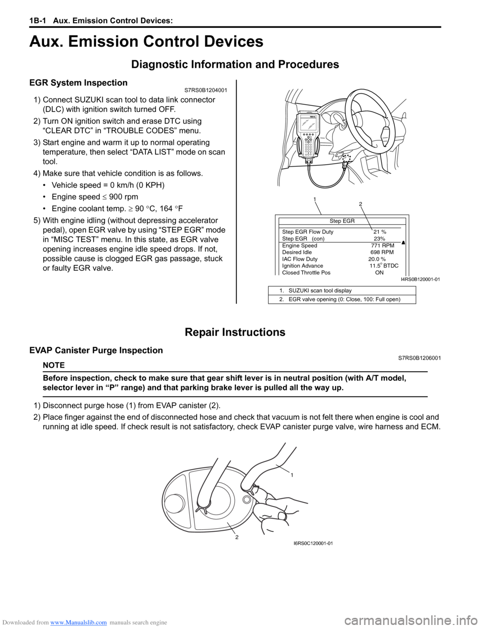
EGR System InspectionS7RS0B1204001
1) Connect SUZUKI scan tool to data link connector (DLC) with ignition switch turned OFF.
2) Turn ON ignition switch and erase DTC using “CLEAR DTC” in “TROUBLE CODES” menu.
3) Start engine and warm it up to normal operating temperature, then select “DATA LIST” mode on scan
tool.
4) Make sure that vehicle condition is as follows.
• Vehicle speed = 0 km/h (0 KPH)
• Engine speed ≤ 900 rpm
• Engine coolant temp. ≥ 90 °C, 164 °F
5) With engine idling (without depressing accelerator pedal), open EGR valve by using “STEP EGR” mode
in “MISC TEST” menu. In this state, as EGR valve
opening increases engine idle speed drops. If not,
possible cause is clogged EGR gas passage, stuck
or faulty EGR valve.
Repair Instructions
EVAP Canister Purge InspectionS7RS0B1206001
NOTE
Before inspection, check to make sure that gear shift lever is in neutral position (with A/T model,
selector lever in “P” range) and that parking brake lever is pulled all the way up.
1) Disconnect purge hose (1) from EVAP canister (2).
2) Place finger against the end of disconne cted hose and check that vacuum is not felt there when engine is cool and
running at idle speed. If check result is not satisfacto ry, check EVAP canister purge valve, wire harness and ECM.
1. SUZUKI scan tool display
2. EGR valve opening (0: Close, 100: Full open)
Step EGR
Step EGR Flow Duty 21 %
Step EGR (con) 23%
Engine Speed 771 RPM
Desired Idle 698 RPM
IAC Flow Duty 20.0 %
Ignition Advance 11.5 BTDC
Closed Throttle Pos ON
1 2
I4RS0B120001-01
1
2
I6RS0C120001-01
Page 274 of 1496
Downloaded from www.Manualslib.com manuals search engine 1C-2 Engine Electrical Devices:
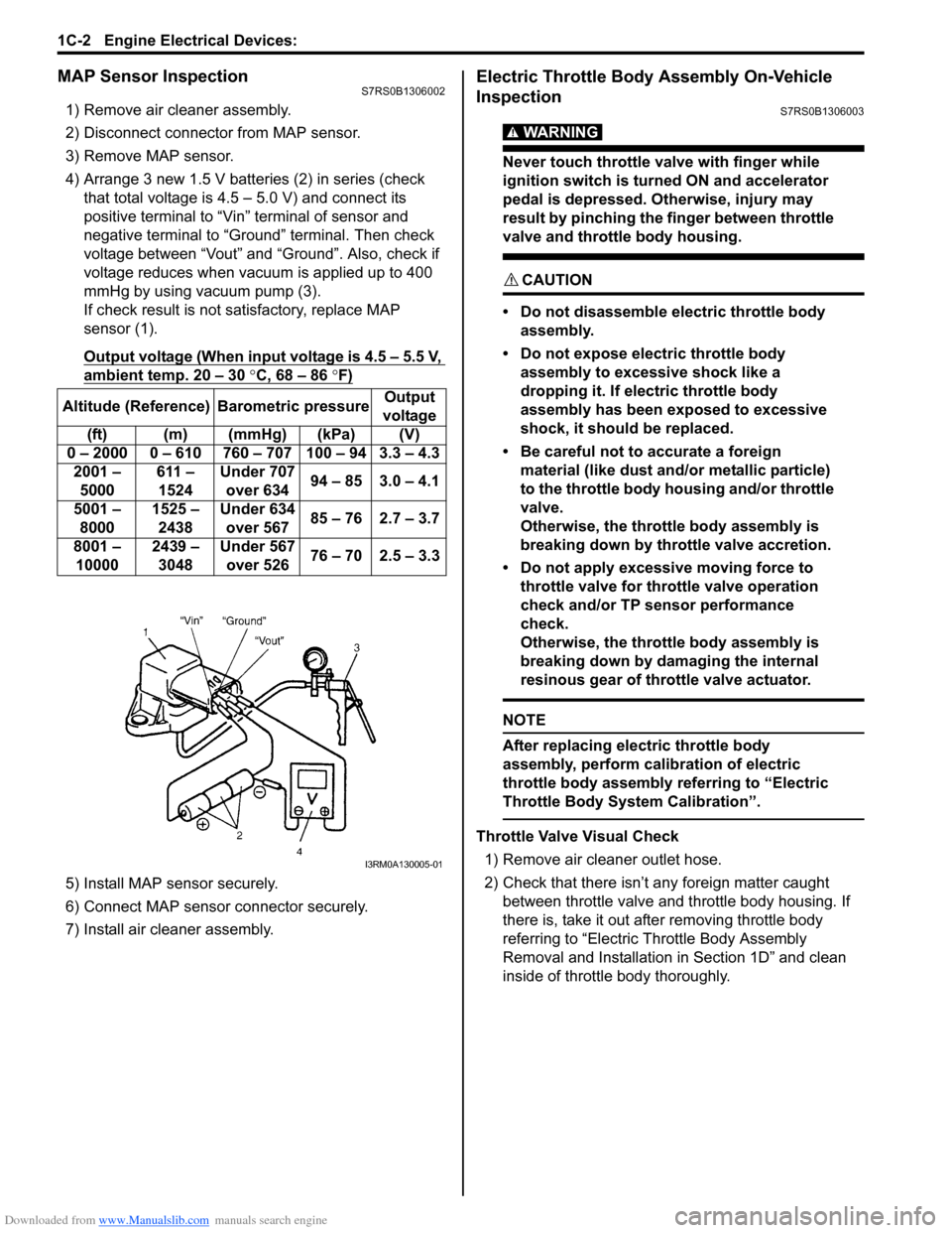
MAP Sensor InspectionS7RS0B1306002
1) Remove air cleaner assembly.
2) Disconnect connector from MAP sensor.
3) Remove MAP sensor.
4) Arrange 3 new 1.5 V batteries (2) in series (check that total voltage is 4.5 – 5.0 V) and connect its
positive terminal to “Vin ” terminal of sensor and
negative terminal to “Ground” terminal. Then check
voltage between “Vout” and “Ground”. Also, check if
voltage reduces when vacuum is applied up to 400
mmHg by using vacuum pump (3).
If check result is not satisfactory, replace MAP
sensor (1).
Output voltage (When input voltage is 4.5 – 5.5 V,
ambient temp. 20 – 30 °C, 68 – 86 °F)
5) Install MAP sensor securely.
6) Connect MAP sensor connector securely.
7) Install air cleaner assembly.
Electric Throttle Body Assembly On-Vehicle
Inspection
S7RS0B1306003
WARNING!
Never touch throttle valve with finger while
ignition switch is turned ON and accelerator
pedal is depressed. Otherwise, injury may
result by pinching the finger between throttle
valve and throttle body housing.
CAUTION!
• Do not disassemble electric throttle body assembly.
• Do not expose electric throttle body assembly to excessive shock like a
dropping it. If electric throttle body
assembly has been exposed to excessive
shock, it should be replaced.
• Be careful not to accurate a foreign material (like dust and/ or metallic particle)
to the throttle body housing and/or throttle
valve.
Otherwise, the throttle body assembly is
breaking down by throttle valve accretion.
• Do not apply excessive moving force to throttle valve for thro ttle valve operation
check and/or TP sensor performance
check.
Otherwise, the throttle body assembly is
breaking down by damaging the internal
resinous gear of throttle valve actuator.
NOTE
After replacing electric throttle body
assembly, perform calibration of electric
throttle body assembly referring to “Electric
Throttle Body System Calibration”.
Throttle Valve Visual Check
1) Remove air cleaner outlet hose.
2) Check that there isn’t any foreign matter caught between throttle valve and throttle body housing. If
there is, take it out after removing throttle body
referring to “Electric Th rottle Body Assembly
Removal and Installation in Section 1D” and clean
inside of throttle body thoroughly.
Altitude (Reference) Barometric pressure
Output
voltage
(ft) (m) (mmHg) (kPa) (V)
0 – 2000 0 – 610 760 – 707 100 – 94 3.3 – 4.3 2001 – 5000 611 –
1524 Under 707
over 634 94 – 85 3.0 – 4.1
5001 – 8000 1525 –
2438 Under 634
over 567 85 – 76 2.7 – 3.7
8001 – 10000 2439 –
3048 Under 567
over 526 76 – 70 2.5 – 3.3
I3RM0A130005-01
Page 276 of 1496
Downloaded from www.Manualslib.com manuals search engine 1C-4 Engine Electrical Devices:
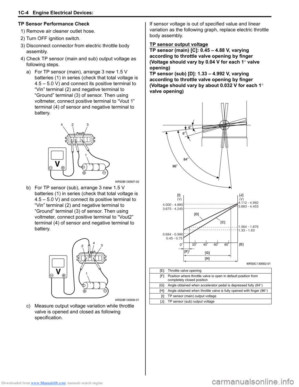
TP Sensor Performance Check1) Remove air cleaner outlet hose.
2) Turn OFF ignition switch.
3) Disconnect connector from electric throttle body assembly.
4) Check TP sensor (main and sub) output voltage as following steps.
a) For TP sensor (main), arrange 3 new 1.5 V batteries (1) in series (c heck that total voltage is
4.5 – 5.0 V) and connect its positive terminal to
“Vin” terminal (2) and negative terminal to
“Ground” terminal (3) of sensor. Then using
voltmeter, connect positive terminal to “Vout 1”
terminal (4) of sensor and negative terminal to
battery.
b) For TP sensor (sub), arrange 3 new 1.5 V batteries (1) in series (c heck that total voltage is
4.5 – 5.0 V) and connect its positive terminal to
“Vin” terminal (2) and negative terminal to
“Ground” terminal (3) of sensor. Then using
voltmeter, connect positive terminal to “Vout2”
terminal (4) of sensor and negative terminal to
battery.
c) Measure output voltage variation while throttle valve is opened and closed as following
specification. If sensor voltage is out of specified value and linear
variation as the following gra
ph, replace electric throttle
body assembly.
TP sensor output voltage
TP sensor (main) [C]: 0.45 – 4.88 V, varying
according to throttle valve opening by finger
(Voltage should vary by 0.04 V for each 1° valve
opening)
TP sensor (sub) [D]: 1.33 – 4.992 V, varying
according to throttle valve opening by finger
(Voltage should vary by about 0.032 V for each 1 °
valve opening)
1
42 3
I4RS0B130007-02
1
3
2 4
I4RS0B130008-01
[E]: Throttle valve opening
[F]: Position where throttle valve is open in default position from completely closed position
[G]: Angle obtained when accelerator pedal is depressed fully (84 °)
[H]: Angle obtained when throttle valve is fully opened with finger (96 °)
[I]: TP sensor (main) output voltage
[J]: TP sensor (sub) output voltage
[D]
[C][J]
(V)
[I]
(V)
[F] [G] [E]
0.45 - 0.75
0.684 - 0.996 3.675 - 4.245 4.000 - 4.880
1.33 - 1.63 1.564 - 1.876 3.883 - 4.453 4.112 - 4.992
[H]
I6RS0C130002-01