2006 SUZUKI SWIFT Center lock
[x] Cancel search: Center lockPage 1290 of 1496
Downloaded from www.Manualslib.com manuals search engine 9B-8 Lighting Systems:
Headlight Switch (in Lighting Switch) Removal
and Installation
S7RS0B9206004
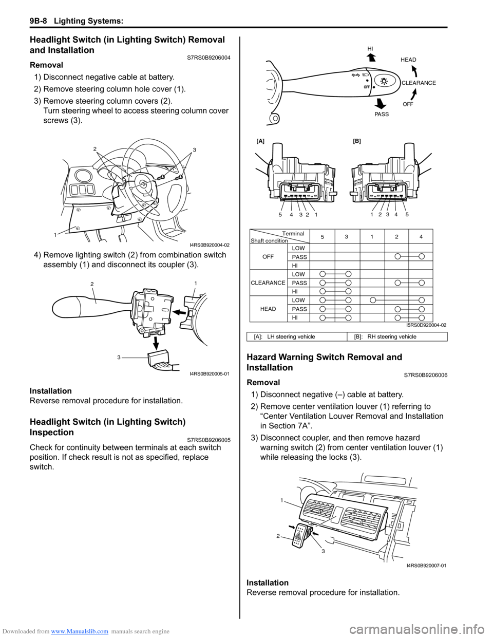
Removal1) Disconnect negative cable at battery.
2) Remove steering column hole cover (1).
3) Remove steering column covers (2). Turn steering wheel to acce ss steering column cover
screws (3).
4) Remove lighting switch (2 ) from combination switch
assembly (1) and disconnect its coupler (3).
Installation
Reverse removal procedure for installation.
Headlight Switch (in Lighting Switch)
Inspection
S7RS0B9206005
Check for continuity between terminals at each switch
position. If check result is not as specified, replace
switch.
Hazard Warning Switch Removal and
Installation
S7RS0B9206006
Removal 1) Disconnect negative (–) cable at battery.
2) Remove center ventilation louver (1) referring to
“Center Ventilation Louver Removal and Installation
in Section 7A”.
3) Disconnect coupler, and then remove hazard warning switch (2) from center ventilation louver (1)
while releasing the locks (3).
Installation
Reverse removal procedure for installation.
1
32
I4RS0B920004-02
1
2
3
I4RS0B920005-01
[A]: LH steering vehicle [B]: RH steering vehicle
Terminal
Shaft condition
OFF 5
3124
LOW
PASS
HI
LOW
PASS
HI LOW
PASS
HI
CLEARANCE
HEAD
HEADCLEARANCE
OFF
HI
PA S S
54321
54321
[A][B]
I5RS0D920004-02
1
2 3
I4RS0B920007-01
Page 1353 of 1496
Downloaded from www.Manualslib.com manuals search engine Security and Locks: 9F-7
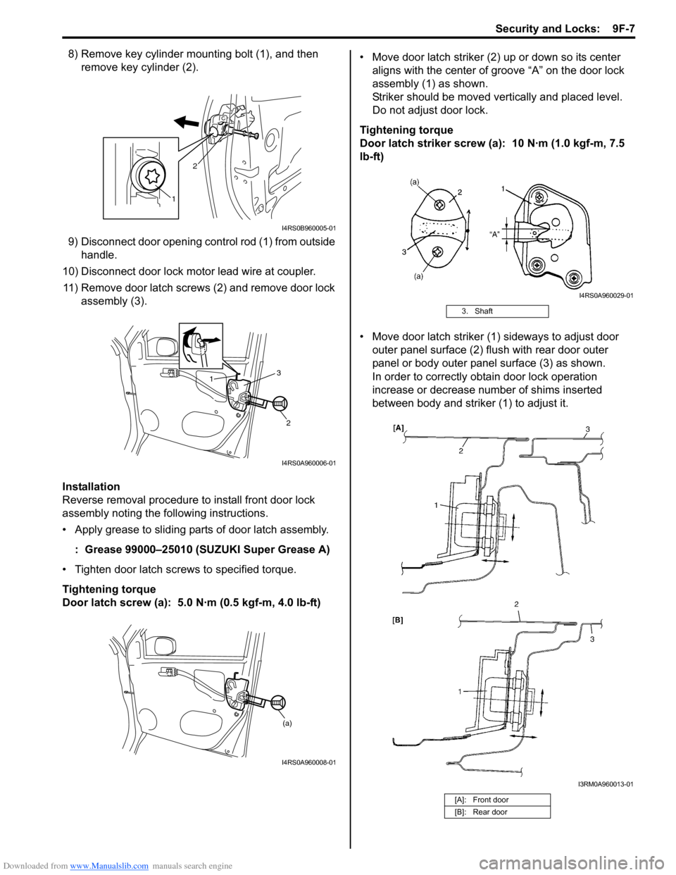
8) Remove key cylinder mounting bolt (1), and then remove key cylinder (2).
9) Disconnect door opening control rod (1) from outside handle.
10) Disconnect door lock motor lead wire at coupler. 11) Remove door latch screws (2) and remove door lock assembly (3).
Installation
Reverse removal procedure to install front door lock
assembly noting the following instructions.
• Apply grease to sliding parts of door latch assembly.
: Grease 99000–25010 (SUZUKI Super Grease A)
• Tighten door latch screws to specified torque.
Tightening torque
Door latch screw (a): 5.0 N·m (0.5 kgf-m, 4.0 lb-ft) • Move door latch striker (2) up or down so its center
aligns with the center of groove “A” on the door lock
assembly (1) as shown.
Striker should be moved vertically and placed level.
Do not adjust door lock.
Tightening torque
Door latch striker screw (a): 10 N·m (1.0 kgf-m, 7.5
lb-ft)
• Move door latch striker (1) sideways to adjust door outer panel surface (2) flush with rear door outer
panel or body outer panel surface (3) as shown.
In order to correctly obtain door lock operation
increase or decrease number of shims inserted
between body and striker (1) to adjust it.
1 2
I4RS0B960005-01
1
2
3
I4RS0A960006-01
(a)
I4RS0A960008-01
3. Shaft
[A]: Front door
[B]: Rear door
I4RS0A960029-01
I3RM0A960013-01
Page 1358 of 1496
Downloaded from www.Manualslib.com manuals search engine 9F-12 Security and Locks:
Installation
Reverse removal procedure to install rear end door lock
assembly noting the following instruction.
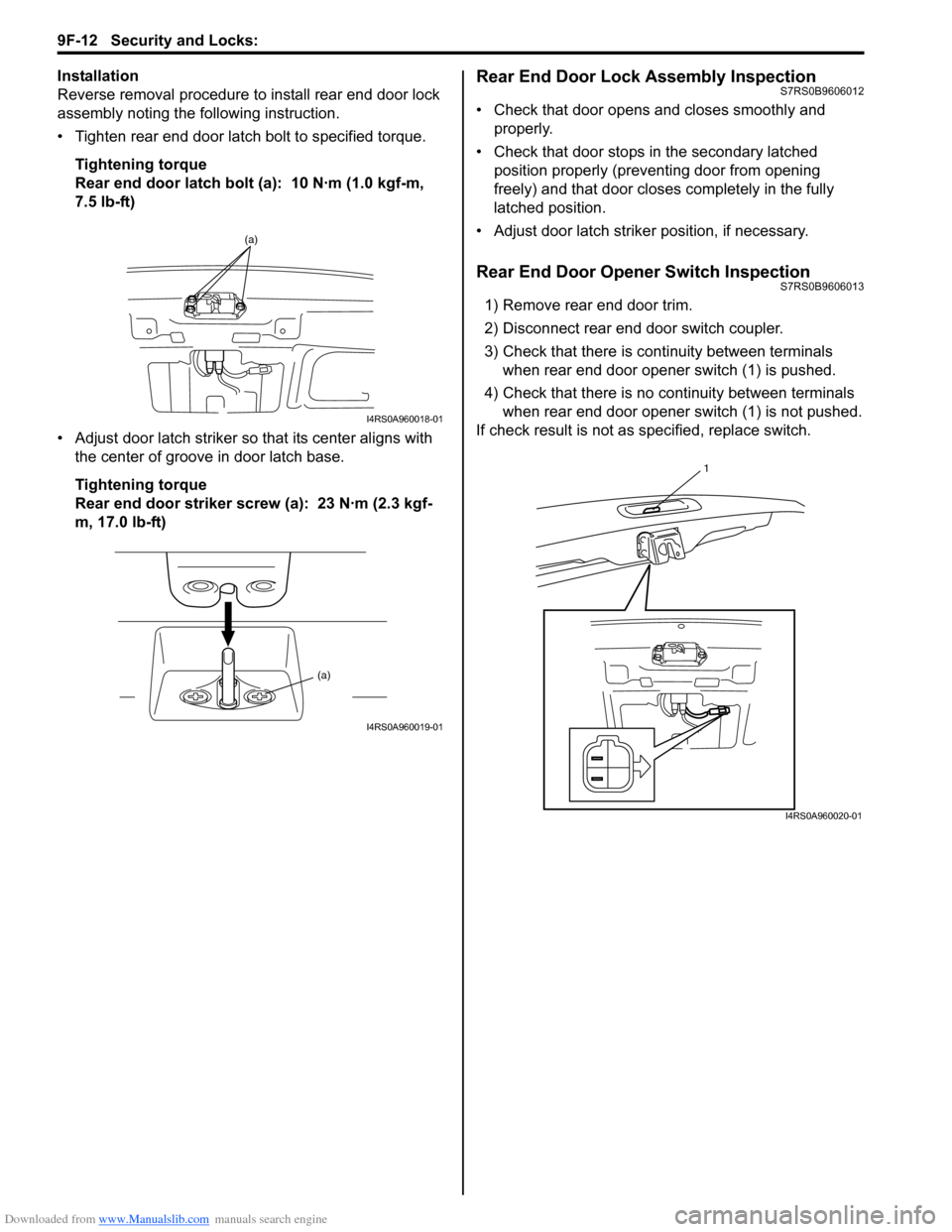
• Tighten rear end door latch bolt to specified torque.
Tightening torque
Rear end door latch bolt (a): 10 N·m (1.0 kgf-m,
7.5 lb-ft)
• Adjust door latch striker so that its center aligns with the center of groove in door latch base.
Tightening torque
Rear end door striker screw (a): 23 N·m (2.3 kgf-
m, 17.0 lb-ft)Rear End Door Lock Assembly InspectionS7RS0B9606012
• Check that door opens and closes smoothly and properly.
• Check that door stops in the secondary latched position properly (preventing door from opening
freely) and that door closes completely in the fully
latched position.
• Adjust door latch strike r position, if necessary.
Rear End Door Opener Switch InspectionS7RS0B9606013
1) Remove rear end door trim.
2) Disconnect rear end door switch coupler.
3) Check that there is continuity between terminals
when rear end door opener switch (1) is pushed.
4) Check that there is no continuity between terminals when rear end door opener switch (1) is not pushed.
If check result is not as specified, replace switch.
(a)
I4RS0A960018-01
(a)
I4RS0A960019-01
1
I4RS0A960020-01
Page 1366 of 1496
Downloaded from www.Manualslib.com manuals search engine 9G-4 Seats:
Rear Seat Removal and InstallationS7RS0B9706004
Removal1) Fold rear seat back forward.
2) Remove seat mounting bolts and nuts to remove seat assembly.
3) Disassemble and repair seat as necessary.
Installation
Reverse removal procedure to install rear seat.
• Tighten seat back striker mounting bolts according to “Rear Seat Components”.
• Torque to specifications in “Rear Seat Components”.
• When installing seat cushion, align seat cushion hook with center hinge bracket.
Specifications
Tightening Torque SpecificationsS7RS0B9707001
NOTE
The specified tightening torque is also described in the following.
“Front Seat Components”
“Rear Seat Components”
Reference:
For the tightening torque of fastener not specified in this section, refer to “Fasteners Information in Section 0A”.
Special Tools and Equipment
Recommended Service MaterialS7RS0B9708001
NOTE
Required service material is also described in the following.
“Front Seat Components”
Material SUZUKI recommended product or Specification Note
Thread lock cement Thread Lock Cement Super 1303B P/No.: 99000–32030 �)
Thread Lock Cement 1305 P/No.: 99000–32100 �)
Page 1380 of 1496
Downloaded from www.Manualslib.com manuals search engine 9K-3 Body Structure:
Specifications
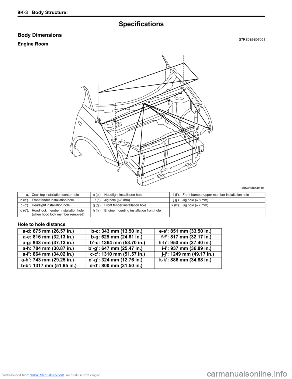
Body DimensionsS7RS0B9B07001
Engine Room
Hole to hole distance
g’
b
ckg
i
a
b’
c’
d
d’
e
e’
f’
f
h
h’
i’ j
k’
j’
I4RS0A9B0003-01
a. Cowl top installation center hole e (e’). Headlight installation hole i (i’). Front bumper upper member installation hole
b (b’). Front fender installation hole f (f’). Jig hole (φ 8 mm) j (j’). Jig hole (φ 8 mm)
c (c’). Headlight installation hole g (g’). Front fender installation hole k (k’). Jig hole (φ 7 mm)
d (d’). Hood lock member installation hole (when hood lock member removed) h (h’). Engine mounting installation front hole
a-d: 675 mm (26.57 in.) b-c: 343 mm (13.50 in.) e-e’: 851 mm (33.50 in.)
a-e: 816 mm (32.13 in.) b-g: 625 mm (24.61 in.) f-f’: 817 mm (32.17 in.)
a-g: 943 mm (37.13 in.) b’-c: 1364 mm (53.70 in.) h-h’: 950 mm (37.40 in.)
a-h: 784 mm (30.87 in.) b’-g’: 647 mm (25.47 in.) i-i’: 937 mm (36.89 in.)
a-f’: 864 mm (34.02 in.) c-c’: 1310 mm (51.57 in.) j-j’: 1249 mm (49.17 in.)
a-h’: 743 mm (29.25 in.) c’-g’: 324 mm (12.76 in.) k-k’: 886 mm (34.88 in.)
b-b’: 1317 mm (51.85 in.) d-d’: 800 mm (31.50 in.)
Page 1463 of 1496
Downloaded from www.Manualslib.com manuals search engine Keyless Start System: 10E-1
Control Systems
Keyless Start System
General Description
Keyless Start System DescriptionS7RS0BA501001
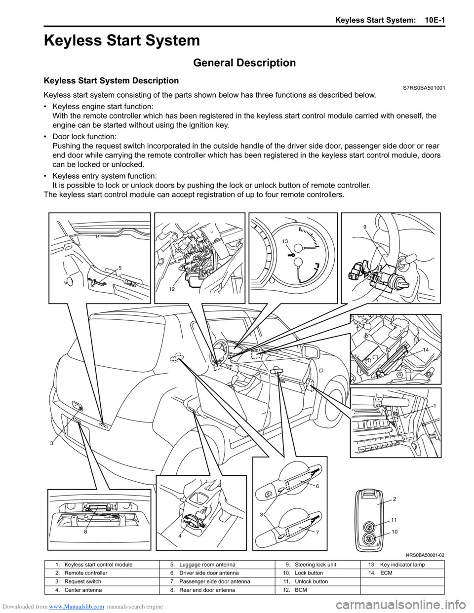
Keyless start system consisting of the parts shown below has three functions as described below.
• Keyless engine start function:With the remote controller which has been registered in the keyless start control module carried with oneself, the
engine can be started without using the ignition key.
• Door lock function: Pushing the request switch incorporated in the outside handl e of the driver side door, passenger side door or rear
end door while carrying the remote controller which has been registered in the keyless start control module, doors
can be locked or unlocked.
• Keyless entry system function: It is possible to lock or unlock doors by push ing the lock or unlock button of remote controller.
The keyless start control module can accept regi stration of up to four remote controllers.
5
12
13
9
14
1
2
6
3
748
3
11
10
I4RS0BA50001-02
1. Keyless start control module 5. Luggage room antenna 9. Steering lock unit13. Key indicator lamp
2. Remote controller 6. Driver side door antenna10. Lock button14. ECM
3. Request switch 7. Passenger side door antenna11. Unlock button
4. Center antenna 8. Rear end door antenna12. BCM
Page 1464 of 1496
Downloaded from www.Manualslib.com manuals search engine 10E-2 Keyless Start System:
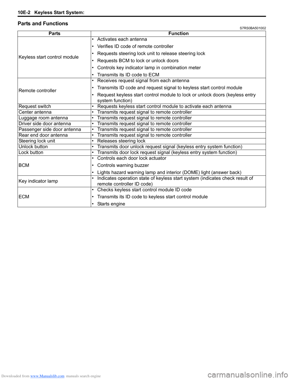
Parts and FunctionsS7RS0BA501002
PartsFunction
Keyless start control module • Activates each antenna
• Verifies ID code of remote controller
• Requests steering lock unit to release steering lock
• Requests BCM to lock or unlock doors
• Controls key indicator la
mp in combination meter
• Transmits its ID code to ECM
Remote controller • Receives request signal from each antenna
• Transmits ID code and request signal to keyless start control module
• Request keyless start control module to lock or unlock doors (keyless entry
system function)
Request switch • Requests keyless start control module to activate each antenna
Center antenna • Transmits request signal to remote controller
Luggage room antenna • Transmits request signal to remote controller
Driver side door antenna • Transmits request signal to remote controller
Passenger side door antenna • Transmits request signal to remote controller
Rear end door antenna • Transmits request signal to remote controller
Steering lock unit • Releases steering lock
Unlock button • Transmits door unlock request signal (keyless entry system function)
Lock button • Transmits door lock request signal (keyless entry system function)
BCM • Controls each door lock actuator
• Controls warning buzzer
• Lights hazard warning lamp and interior (DOME) light (answer back)
Key indicator lamp • Indicates operation state of keyless start system (indicates check result of
remote controller ID code)
ECM • Checks keyless start control module ID code
• Transmits its ID code to keyless start control module
• Starts engine
Page 1465 of 1496
Downloaded from www.Manualslib.com manuals search engine Keyless Start System: 10E-3
Keyless Engine Start FunctionS7RS0BA501003
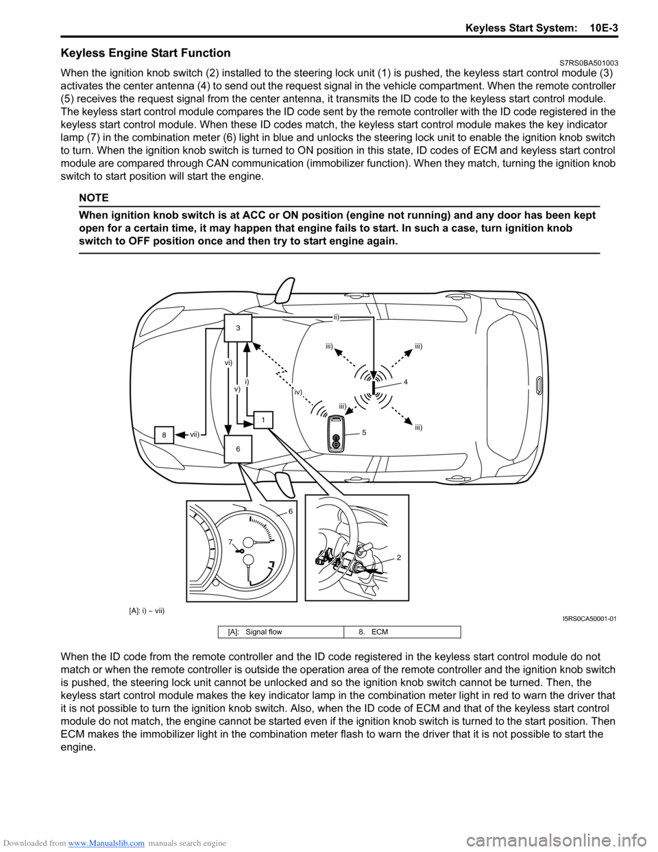
When the ignition knob switch (2) installed to the steering lock unit (1) is pushed, the keyless start control module (3)
activates the center antenna (4) to send out the request signa l in the vehicle compartment. When the remote controller
(5) receives the request signal from th e center antenna, it transmits the ID code to the keyless start control module.
The keyless start control module compares the ID code sent by the remote controller with the ID code registered in the
keyless start control module. When these ID codes match, the keyless start control module makes the key indicator
lamp (7) in the combination meter (6) light in blue and unlocks the steering lock unit to enable the ignition knob switch
to turn. When the ignition knob switch is turned to ON posit ion in this state, ID codes of ECM and keyless start control
module are compared through CA N communication (immobilizer function). Wh en they match, turning the ignition knob
switch to start position will start the engine.
NOTE
When ignition knob switch is at ACC or ON position (engine not running) and any door has been kept
open for a certain time, it may happen that engine fails to start. In such a case, turn ignition knob
switch to OFF position once and then try to start engine again.
When the ID code from the remote controller and the ID code registered in the keyless start control module do not
match or when the remote controller is outside the operation area of the remote controller and the ignition knob switch
is pushed, the steering lock unit cannot be unlocked and so the ignition knob switch cannot be turned. Then, the
keyless start control module makes the key indicator lamp in t he combination meter light in red to warn the driver that
it is not possible to turn the ignition knob switch. Also, when the ID code of ECM and that of the keyless start control
module do not match, the engine cannot be started even if the ignition knob switch is turned to the start position. Then
ECM makes the immobilizer light in the combination mete r flash to warn the driver that it is not possible to start the
engine.
8 3
1
6 ii)
iii) iii)
iii)
iii)
iv)
i)
v)
vi)
vii)
7 6
2
[A]: i) ~ vii)
54
I5RS0CA50001-01
[A]: Signal flow
8. ECM