2006 SUZUKI SWIFT Adjust
[x] Cancel search: AdjustPage 414 of 1496

Downloaded from www.Manualslib.com manuals search engine 1J-4 Charging System:
Diagnostic Information and Procedures
Battery InspectionS7RS0B1A04001
Common Causes of Failure
A battery is not designed to last indefinitely; however, with proper care, it will provide many years of service. If the
battery performs satisfactorily during te st but fails to operate properly for no apparent reason, the following are some
factors that may point to the cause of trouble:
• Accessories left on overnight or for an extended period without the generator operating.
• Slow average driving speeds for short periods.
• Electrical load exceeding generator output partic ularly with addition of aftermarket equipment.
• Defects in charging system such as high resistance, s lipping drive belt, loose generator output terminal, faulty
generator or voltage regulator, Refer to “Generator Symptom Diagnosis”.
• Battery abuse, including failure to keep battery cable terminals clean and tight or loose battery hold down.
• Mechanical problems in electrical sys tem such as shorted or pinched wires.
Visual Inspection
Check for obvious damage, such as cracked or broken case or cover, that could permit loss of electrolyte. If obvious
damage is noted, replace battery. Determine cause of damage and correct as needed.
Generator Symptom DiagnosisS7RS0B1A04002
CAUTION!
• Do not mistake polarities of “IG” terminal and “L” terminal.
• Do not create short circuit between “IG” and “L” terminals. Always connect these terminals through a lamp.
• Do not connect any load between “L” and “E” terminals.
• When connecting charger or booster battery to vehicle battery, refer to “Jump Starting in Case of Emergency”.
Trouble in charging system will show up as one or more of the following conditions:
1) Faulty indicator lamp operation.
2) An undercharged battery as evidenced by slow cranking or indicator dark.
3) An overcharged battery as evidenced by ex cessive spewing of electrolyte from vents.
Condition Possible cause Correction / Reference Item
Noisy generator Loose drive belt Adjust or replace drive belt.
Loose drive belt pulley Tighten by specified torque.
Loose mounting bolts Tighten by specified torque.
Worn or dirty bearings Replace.
Defective diode or stator Replace.
Charge light does not
light with ignition ON and
engine off Fuse blown
Replace fuse and check for shorted circuit.
Indicator lamp (LED) faulty Replace combination meter.
Wiring connection loose Tighten loose connection.
IC regulator or field coil faulty Replace.
Poor contact between brush and slip
ring Repair or replace.
Charge light does not go
out with engine running
(battery requires frequent
recharging) Drive belt loose or worn
Adjust or replace drive belt.
IC regulator or generator faulty Replace.
Wiring faulty Repair wiring.
Page 417 of 1496
Downloaded from www.Manualslib.com manuals search engine Charging System: 1J-7
With Charging Equipment
CAUTION!
When jump starting engine with charging
equipment, be sure equipment used is 12-
volt and negative ground. Do not use 24-volt
charging equipment. Using such equipment
can cause serious damage to electrical
system or electronic parts.
Battery Dismounting and RemountingS7RS0B1A06002
WARNING!
When handling battery, following safety
precautions should be followed:
• Hydrogen gas is produced by battery. A flame or spark near battery may cause the
gas to ignite.
• Battery fluid is highly acidic. Avoid spilling on clothing or other fabric. Any spilled
electrolyte should be flushed with large
quantity of water and cleaned immediately.
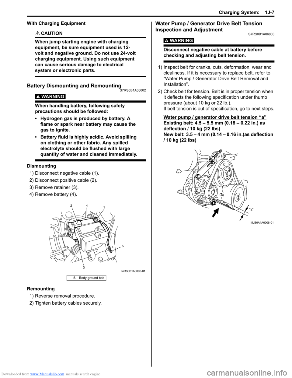
Dismounting
1) Disconnect negative cable (1).
2) Disconnect positive cable (2).
3) Remove retainer (3).
4) Remove battery (4).
Remounting 1) Reverse removal procedure.
2) Tighten battery cables securely.
Water Pump / Generator Drive Belt Tension
Inspection and Adjustment
S7RS0B1A06003
WARNING!
Disconnect negative cable at battery before
checking and adjusting belt tension.
1) Inspect belt for cranks, cuts, deformation, wear and clealiness. If it is necessary to replace belt, refer to
“Water Pump / Generator Drive Belt Removal and
Installation”.
2) Check belt for tension. Belt is in proper tension when it deflects the following specification under thumb
pressure (about 10 kg or 22 lb.).
If belt tension is out of spec ification, go to next steps.
Water pump / generator drive belt tension
“a”
Existing belt: 4.5 – 5.5 mm (0.18 – 0.22 in.) as
deflection / 10 kg (22 lbs)
New belt: 3.5 – 4 mm (0.14 – 0.16 in.)as deflection
/ 10 kg (22 lbs)
5. Body ground bolt
1
3 5
2
4
I4RS0B1A0006-01
“a”
I5JB0A1A0008-01
Page 418 of 1496
Downloaded from www.Manualslib.com manuals search engine 1J-8 Charging System:
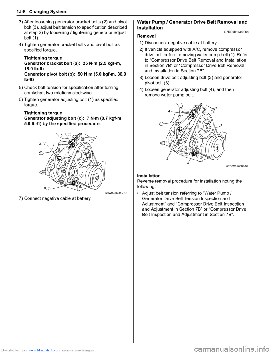
3) After loosening generator bracket bolts (2) and pivot bolt (3), adjust belt tensio n to specification described
at step 2) by loosening / tightening generator adjust
bolt (1).
4) Tighten generator bracket bolts and pivot bolt as specified torque.
Tightening torque
Generator bracket bolt (a): 25 N·m (2.5 kgf-m,
18.0 lb-ft)
Generator pivot bolt (b): 50 N·m (5.0 kgf-m, 36.0
lb-ft)
5) Check belt tension for specification after turning crankshaft two rotations clockwise.
6) Tighten generator adjusting bolt (1) as specified torque.
Tightening torque
Generator adjusting bolt (c): 7 N·m (0.7 kgf-m,
5.0 lb-ft) by the specified procedure.
7) Connect negative cable at battery.Water Pump / Generator Drive Belt Removal and
Installation
S7RS0B1A06004
Removal 1) Disconnect negative cable at battery.
2) If vehicle equipped with A/C, remove compressor drive belt before removing water pump belt (1). Refer
to “Compressor Drive Belt Removal and Installation
in Section 7B” or “Compr essor Drive Belt Removal
and Installation in Section 7B”.
3) Loosen drive belt adjusting bolt (2) and generator pivot bolt (3).
4) Loosen generator adjusting bolt (4), and then remove water pump belt.
Installation
Reverse removal procedure for installation noting the
following.
• Adjust belt tension referring to “Water Pump / Generator Drive Belt Tension Inspection and
Adjustment” and “Compressor Drive Belt Inspection
and Adjustment in Section 7B” or “Compressor Drive
Belt Inspection and Adjustment in Section 7B”.
1, (c)
2, (a)
3, (b)
I5RW0C160007-01
4
23
1
I6RS0C1A0002-01
Page 419 of 1496
Downloaded from www.Manualslib.com manuals search engine Charging System: 1J-9
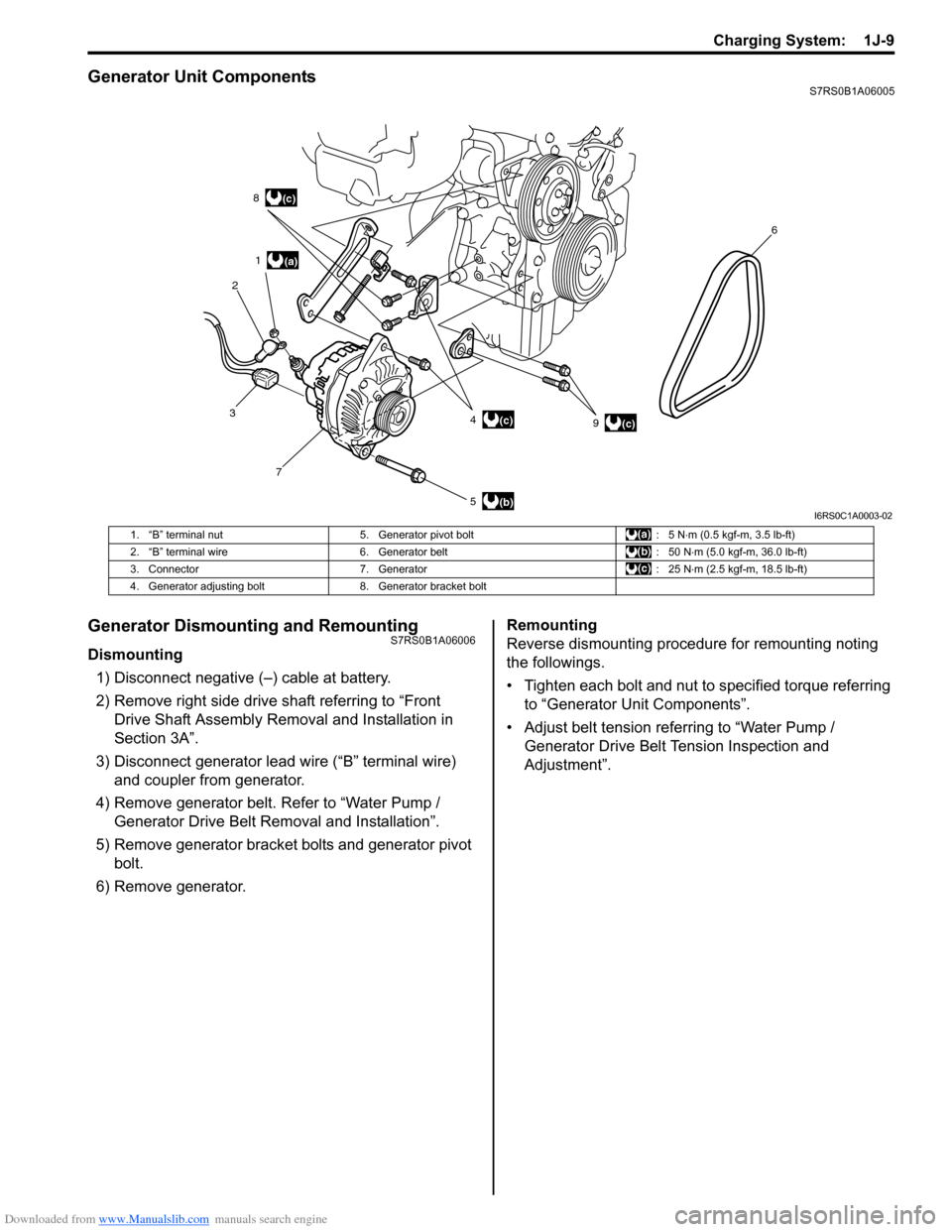
Generator Unit ComponentsS7RS0B1A06005
Generator Dismounting and RemountingS7RS0B1A06006
Dismounting1) Disconnect negative (–) cable at battery.
2) Remove right side drive shaft referring to “Front Drive Shaft Assembly Removal and Installation in
Section 3A”.
3) Disconnect generator lead wire (“B” terminal wire) and coupler from generator.
4) Remove generator belt. Refer to “Water Pump / Generator Drive Belt Re moval and Installation”.
5) Remove generator bracket bolts and generator pivot bolt.
6) Remove generator. Remounting
Reverse dismounting procedure for remounting noting
the followings.
• Tighten each bolt and nut to specified torque referring
to “Generator Unit Components”.
• Adjust belt tension referring to “Water Pump / Generator Drive Belt Tension Inspection and
Adjustment”.
(a)
(b)
(c)
1
2 8
3 7 5 49 6(c)
(c)
I6RS0C1A0003-02
1. “B” terminal nut
5. Generator pivot bolt : 5 N⋅m (0.5 kgf-m, 3.5 lb-ft)
2. “B” terminal wire 6. Generator belt : 50 N⋅m (5.0 kgf-m, 36.0 lb-ft)
3. Connector 7. Generator : 25 N⋅m (2.5 kgf-m, 18.5 lb-ft)
4. Generator adjusting bolt 8. Generator bracket bolt
Page 423 of 1496
Downloaded from www.Manualslib.com manuals search engine Charging System: 1J-13
Specifications
Charging System SpecificationsS7RS0B1A07001
Battery
Battery
: 48AH/20H, 40.6AH/5H 12 V
Generator
Tightening Torque SpecificationsS7RS0B1A07002
NOTE
The specified tightening torque is also described in the following.
“Generator Unit Components”
“Generator Components”
Reference:
For the tightening torque of fastener not specified in this section, refer to “Fasteners Information in Section 0A”.
Nominal output
12 V
Rated capacity 48 Ah/20 h
40.6 Ah/5 h
Cold cranking amperes 300 A (DIN)
Ty p e 80A type
Rated voltage 12 V
Nominal output 80A
Permissible max. speed 18,000 r/min.
No-load speed 1200 r/min. (rpm)
Regulated voltage 14.2 – 14.8 V at 25 ° C (77 °F)
Exposed brush length Standard: 16 mm (0.63 in.)
Limit: 5.0 mm (0.02 in.)
Permissible ambient temperature –30 to 100 °C (–22 to 212 °F)
Polarity Negative ground
Rotation Clockwise viewed from pulley side
Fastening partTightening torque
Note
N ⋅mkgf-mlb-ft
Generator bracket bolt 25 2.5 18.0 �)
Generator pivot bolt 50 5.0 36.0 �)
Generator adjusting bolt 70.7 5.0by the specified
procedure.
�)
Page 429 of 1496
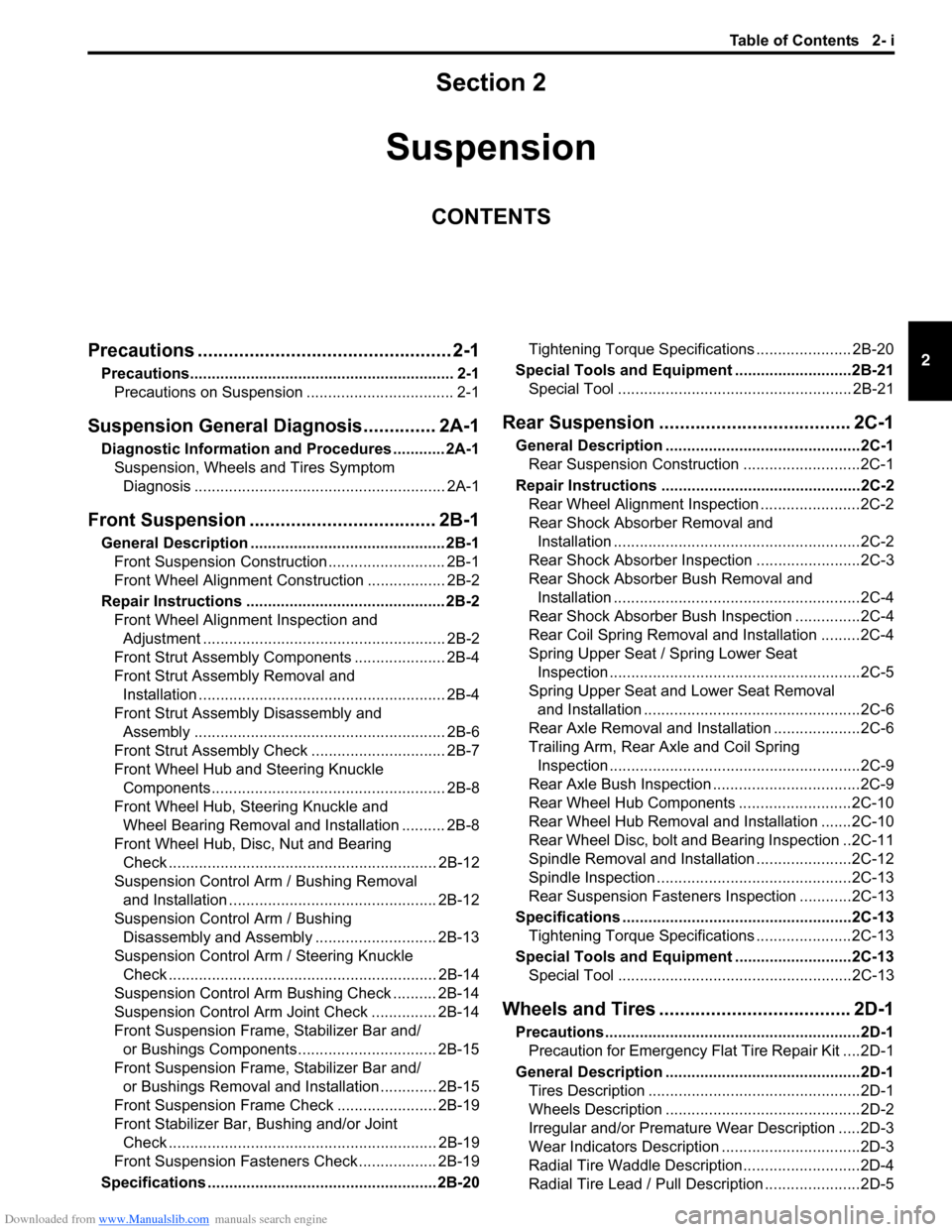
Downloaded from www.Manualslib.com manuals search engine Table of Contents 2- i
2
Section 2
CONTENTS
Suspension
Precautions ................................................. 2-1
Precautions............................................................. 2-1
Precautions on Suspension .................................. 2-1
Suspension General Dia gnosis.............. 2A-1
Diagnostic Information and Procedures ............ 2A-1
Suspension, Wheels and Tires Symptom Diagnosis .......................................................... 2A-1
Front Suspension ........... ......................... 2B-1
General Description ............................................. 2B-1
Front Suspension Construction ........................... 2B-1
Front Wheel Alignment Cons truction .................. 2B-2
Repair Instructions .............................................. 2B-2 Front Wheel Alignment Inspection and Adjustment ........................................................ 2B-2
Front Strut Assembly Comp onents ..................... 2B-4
Front Strut Assembly Removal and Installation ......................................................... 2B-4
Front Strut Assembly Disassembly and Assembly .......................................................... 2B-6
Front Strut Assembly Chec k ............................... 2B-7
Front Wheel Hub and Steering Knuckle Components...................................................... 2B-8
Front Wheel Hub, Steering Knuckle and Wheel Bearing Removal and Installation .......... 2B-8
Front Wheel Hub, Disc, Nut and Bearing Check .............................................................. 2B-12
Suspension Control Arm / Bushing Removal and Installation ................................................ 2B-12
Suspension Control Arm / Bushing Disassembly and Assembly ............................ 2B-13
Suspension Control Arm / Steering Knuckle Check .............................................................. 2B-14
Suspension Control Arm Bushing Check .......... 2B-14
Suspension Control Arm Joint Check ............... 2B-14
Front Suspension Fram e, Stabilizer Bar and/
or Bushings Components................................ 2B-15
Front Suspension Fram e, Stabilizer Bar and/
or Bushings Removal and Installation ............. 2B-15
Front Suspension Frame Ch eck ....................... 2B-19
Front Stabilizer Bar, Bushing and/or Joint Check .............................................................. 2B-19
Front Suspension Fastener s Check .................. 2B-19
Specifications ..................................................... 2B-20 Tightening Torque Specifications ...................... 2B-20
Special Tools and Equipmen t ...........................2B-21
Special Tool ...................................................... 2B-21
Rear Suspension ............ ......................... 2C-1
General Description .............................................2C-1
Rear Suspension Construction ...........................2C-1
Repair Instructions ........... ...................................2C-2
Rear Wheel Alignment Inspection .......................2C-2
Rear Shock Absorber Removal and Installation .........................................................2C-2
Rear Shock Absorber Ins pection ........................2C-3
Rear Shock Absorber Bush Removal and Installation .........................................................2C-4
Rear Shock Absorber Bush Inspection ...............2C-4
Rear Coil Spring Removal and Installation .........2C-4
Spring Upper Seat / Spring Lower Seat Inspection ..........................................................2C-5
Spring Upper Seat and Lower Seat Removal and Installation ..................................................2C-6
Rear Axle Removal and Inst allation ....................2C-6
Trailing Arm, Rear Axle and Coil Spring Inspection ..........................................................2C-9
Rear Axle Bush Inspection ..................................2C-9
Rear Wheel Hub Components ..........................2C-10
Rear Wheel Hub Removal an d Installation .......2C-10
Rear Wheel Disc, bolt and Bearing Inspection ..2C-11
Spindle Removal and Installation ......................2C-12
Spindle Inspection .............................................2C-13
Rear Suspension Fasteners Inspection ............2C-13
Specifications .................... .................................2C-13
Tightening Torque Specifications ......................2C-13
Special Tools and Equipmen t ...........................2C-13
Special Tool ......................................................2C-13
Wheels and Tires ............ ......................... 2D-1
Precautions...........................................................2D-1
Precaution for Emergency Flat Tire Repair Kit ....2D-1
General Description .............................................2D-1 Tires Description .................................................2D-1
Wheels Description .............................................2D-2
Irregular and/or Premature Wear Description .....2D-3
Wear Indicators Description ................................2D-3
Radial Tire Waddle Description...........................2D-4
Radial Tire Lead / Pull Description ......................2D-5
Page 432 of 1496
Downloaded from www.Manualslib.com manuals search engine 2A-1 Suspension General Diagnosis:
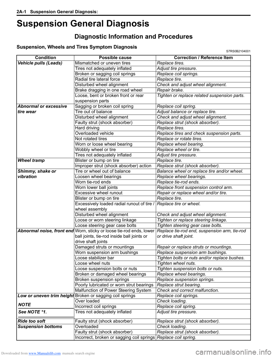
Suspension
Suspension General Diagnosis
Diagnostic Information and Procedures
Suspension, Wheels and Tires Symptom DiagnosisS7RS0B2104001
ConditionPossible cause Correction / Reference Item
Vehicle pulls (Leads) Mismatched or uneven tires Replace tires.
Tires not adequately inflated Adjust tire pressure.
Broken or sagging coil springs Replace coil springs.
Radial tire lateral force Replace tire.
Disturbed wheel alignment Check and adjust wheel alignment.
Brake dragging in one road wheel Repair brake.
Loose, bent or broken front or rear
suspension parts Tighten or replace related suspension parts.
Abnormal or excessive
tire wear Sagging or broken coil spring
Replace coil spring.
Tire out of balance Adjust balance or replace tire.
Disturbed wheel alignment Check and adjust wheel alignment.
Faulty strut (shock absorber) Replace strut (shock absorber).
Hard driving Replace tires.
Overloaded vehicle Replace tires and check suspension parts.
Not rotated tires Replace or rotate tires.
Worn or loose wheel bearing Replace wheel bearing.
Wobbly wheel or tire Replace wheel or tire.
Tires not adequately inflated Adjust tire pressure.
Wheel tramp Blister or bump on tire Replace tire.
Improper strut (shock absorber) action Replace strut (shock absorber).
Shimmy, shake or
vibration Tire or wheel out of balance
Balance wheel or replace tire and/or wheel.
Loosen wheel bearings Replace wheel bearings.
Worn tie-rod ends Replace tie-rod ends.
Worn lower ball joints Replace front suspension control arm.
Excessive wheel runout Repair or replace wheel and/or tire.
Blister or bump on tire Replace tire.
Excessively loaded radial runout of tire /
wheel assembly Replace tire or wheel.
Disturbed wheel alignment Check and adjust wheel alignment.
Loose or worn steering linkage Tighten or replace steering linkage.
Loose steering gear case bolts Tighten steering gear case bolts.
Abnormal noise, front end Worn, sticky or loose tie-rod ends, lower
ball joints, tie-rod in side ball joints or
drive shaft joints Replace tie-rod end, su
spension arm, tie-rod
or drive shaft joint.
Damaged struts or mountings Repair or replace struts or mountings.
Worn suspension arm bushings Replace suspension arm bushings.
Loose stabilizer bar Tighten bolts or nuts and/or replace bushes.
Loose wheel nuts Tighten wheel nuts.
Loose suspension bolts or nuts Tighten suspension bolts or nuts.
Broken or damaged wheel bearings Replace wheel bearings.
Broken suspension springs Replace suspension springs.
Poorly lubricated or worn strut bearings Replace strut bearing.
Malfunction of Power Steering System Check and correct malfunction.
Low or uneven trim height
NOTE
See NOTE *1.
Broken or sagging coil springs Replace coil springs.
Over loaded Check loading.
Incorrect coil springs Replace coil spring.
Tires not adequately inflated Adjust tire pressure.
Ride too soft Faulty strut (shock absorber) Replace strut (shock absorber).
Suspension bottoms Overloaded Check loading.
Faulty strut (shock absorber) Replace strut (shock absorber).
Incorrect, broken or sagging coil springs Replace coil spring.
Page 433 of 1496
Downloaded from www.Manualslib.com manuals search engine Suspension General Diagnosis: 2A-2
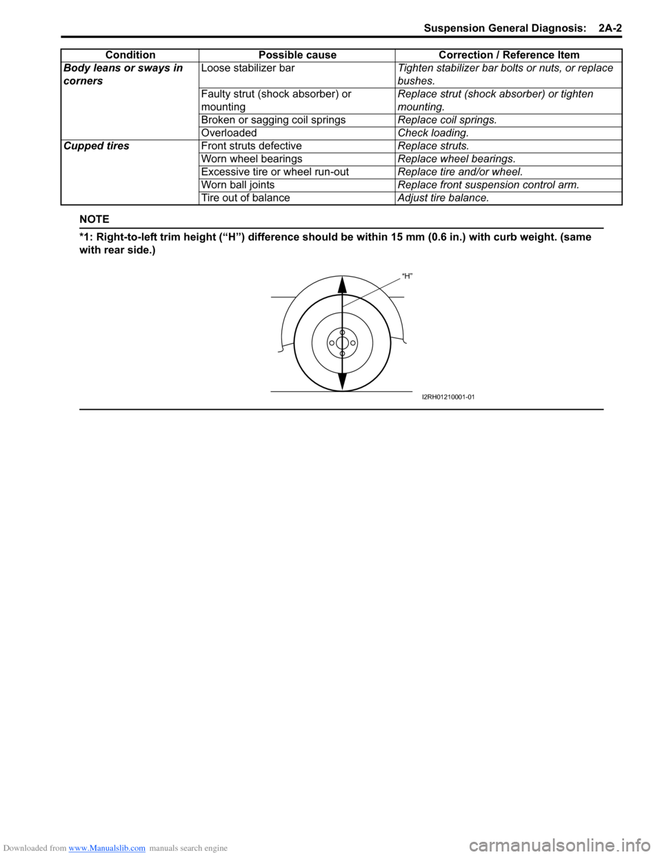
NOTE
*1: Right-to-left trim height (“H”) difference should be within 15 mm (0.6 in.) with curb weight. (same
with rear side.)
Body leans or sways in
corners Loose stabilizer bar
Tighten stabilizer bar bolts or nuts, or replace
bushes.
Faulty strut (shock absorber) or
mounting Replace strut (shock absorber) or tighten
mounting.
Broken or sagging coil springs Replace coil springs.
Overloaded Check loading.
Cupped tires Front struts defective Replace struts.
Worn wheel bearings Replace wheel bearings.
Excessive tire or wheel run-out Replace tire and/or wheel.
Worn ball joints Replace front suspension control arm.
Tire out of balance Adjust tire balance.
Condition Possible cause Correction / Reference Item
“H”
I2RH01210001-01