Page 1248 of 1496
Downloaded from www.Manualslib.com manuals search engine 9A-77 Wiring Systems:
D-1 Headlight System Circuit DiagramS7RS0B910E022
1
Headlight (R) Headlight
(L)
WHT/BLU
RED
Dimmer / Passing switch
Light switch
2
2
BA BC
B
C
33
15
1
22G28
E08
G34
E21
G336
31
RED/BLK
WHT/RED
WHT/RED
10A
25METER
WHT/RED
9
BLK
11
G25
15A
21
15A
20H/L,R H/L,L
RED/WHTRED
10
RED
RED
J/B
10ATAIL
32
RED/WHTRED/WHT
BLU/WHT
5
RED/WHT
E37
G35
E42
J/C
REDRED/WHT
BEAM
FLASH UPLOW
T
P(ED)EL
UP
LOW
OFF
TAIL
HEAD -BT
T
P(H) EL
RY
RED/YEL
"D-4"
BCM
R
WR
RW
E43
J/C
Individual circuit
fuse box (No.1)
Without DRL controller
AWith DRL controller
B
A
5
1
2
3
AB
B
RED/BLK
B
AB5
13AB10
8
AB7
11AB8
10
I5RS0C910942-02
Page 1249 of 1496
Downloaded from www.Manualslib.com manuals search engine Wiring Systems: 9A-78
YELRED/WHT
RED/BLK
3
RED/YEL
5
7 E38 G36
15A WIPER
28
DRL
controller
G3910
WHT/RED
8
BLU/WHT
6
G331
4
9
BLU
BLU
BLK/ORN
BLK/ORN
2
BLK
1
"A-8"
1
5
2
3
B
RY
J/B
BCM
"D-4"
BCM
1110
C
C
J/C
With DRL controller
G15
I5RS0C910943-03
Page 1250 of 1496
Downloaded from www.Manualslib.com manuals search engine 9A-79 Wiring Systems:
D-2 Position, Tail and Licence Plate Light System Circuit DiagramS7RS0B910E023
G
12M0212M03
BLKBLK
BLK
BLK
RED/YEL
RED/YEL
RED/YELRED/YEL
4
3L70
M01
3
5L431
2L47
(L) (R)
(R) (L)
BLK
RED/YELRED/YEL
RED/YEL
7
J/C
L74
E42
15G34
BLK
G25
10A TAIL
32
1
2E071
D
DD
2
ED EE22
BLK
BLK
RED/YEL
J/B
L053E4116
BLK
BLK
E43
J/C
Licence plate
light #1
3
5L20
BLK
BCM
14
11513
WHT/RED
OFF
TAIL
HEAD -BT
T
P(H) EL
A
Front
position light
RED/YEL
Tail light
RY
14
RY
RY
RY
J/C
J/B side connector (BCM)
Without DRL controller
With DRL controller
RHD
LHD
M13A engine, M15A engine
M16A engine
A
BCDEFG
L21
L22
RY
BLK
RED/YEL
RED/YEL
1
2L48
Licence plate
light #2
Licence plate
light #1
Licence
plate
light #2
RED/YEL
RED/BLK
RED/YEL
BLK
3
5G39
DRL
controller
1
2
DE5
13
DE7
11DE
B
F
C8
10
I7RS0B910926-01
Page 1252 of 1496
Downloaded from www.Manualslib.com manuals search engine 9A-81 Wiring Systems:
D-4 Illumination Light System Circuit DiagramS7RS0B910E025
WHT/RED
A/T
Shift
lever
L23
L742
5
BLK
BLKBLK
10A
TAIL
32J/B
15G34
BLK
G25
111814
A/T
B
B
J/C
L24
RED/YEL
RED/YEL
L053
"D-3"
IF EQPD
RY
Switch
J/C J/C
G31
RED/YEL
RY
RED/YEL
Switch
RY
RED/YEL
HVAC
control unit Auto
unit
"E-1"
"E-2""D-6"
OFF
TAIL
HEAD -BT
T
P(H) ELRED/YEL
7
RY
RED/YEL
Audio
"G-1"
D
D
D
D
D
D
D
RY
RED/YEL
D
D
RY
RY
RED/YEL
Multi information
display
"G-2"RED/YEL
RED/YEL
RED/YEL
RY
Tail light (L) "D-2"
RED/YEL
RY
Tail light (R) "D-2"
Licence
plate light
"D-2"
J/B side connector (BCM)
Without DRL controller
With DRL controller
RHD
LHD
A
R
BCDE
Switch
"B-8"
Switch"B-8"
ESP
OFF switch
"F-3"
DE5
13
DE7
11DE
B
C
8
10
DRL
controller
G393
5
RED/YEL
RED/BLK
RED/YEL
D
RY
I7RS0B910927-01
Page 1260 of 1496
Downloaded from www.Manualslib.com manuals search engine 9A-89 Wiring Systems:
E-1 Heater System Circuit DiagramS7RS0B910E032
BRN/WHT
GRN/WHT
10ABACK
24
M
BLK/RED
Relay
BLK/ORN
BLK/ORN
G15
J/C
G01
Air intake control
actuator3 7
1
GRNRED
9
G187
8
G31
J/C
4
G34
BCM
"A-8"GW
BCM
"B-3"
B
BRN
8
RED/YEL
RED/YEL
RED/BLK
RED/BLK
RED/BLK
1013 14 5 6
REAR
DEF REC
FRE
A/CHARF REC
CIRCUIT
HVAC control
unit
10
BB D
D B
B
B
1
RY
"D-4"
"B-3"
BR
J/B
G31
J/C
A A
A
A
BLK
11
A
BLKBLK
3
C
BLK
BLK
9
A
BLK/YEL
LHD RHD
I7RS0B910945-01
Page 1262 of 1496
Downloaded from www.Manualslib.com manuals search engine 9A-91 Wiring Systems:
E-2 Auto A/C System Circuit DiagramS7RS0B910E033
12G53
G51
G52
G51
G52 G52 G51
251211
11
15
17
12V
198
REDGRN
RED/BLK
GRN/RED
RED/YEL
RED/YELRED/BLK
RED/BLKBLU/WHT
M
7133G01
8G34
ILL
Auto A/C panel
Sunload sensor
DLC Auto
unit
Air intake control actuator
BACK
10A24
"A-5"
PW
"A-5"BW"D-4"RY
18
GRN/WHT
"A-8"GW
ECMBCMBCM
BLK/ORN
YEL/BLKPNK
5
PPL/WHT
PPL/WHT
BLK/ORNBLK/YEL
5V 5V
12V
J/B
7
YEL
YEL
"A-8"Y
109
G31
J/C
D
D
G15
J/C
B
B
BLK
BLK
G31
J/C
C
C
G16
J/C
C
C
G15
J/C
A A
11
BLK
A
G16
J/C
A
A
J/C
BG31B B
16
5
I7RS0B910932-01
Page 1263 of 1496
Downloaded from www.Manualslib.com manuals search engine Wiring Systems: 9A-92
G091
2
346
1698G52 G51
G52 G52
G51 G51G52
1
3
7
G495
6
M
G48
M
2
31141413
341
M
2G46
5G33
WHT/RED
WHT/RED
BLK/WHT
GRY/REDGRY/BLUWHTWHT/BLUBRN/WHTBRN/YELWHT/BLKGRN
WHTYELWHTWHT/BLU
GRNGRNBLKGRNGRN
BLK/YELBLK/YEL
BLK/WHTGRYBLK/WHTBLU/RED
Blower motor controller
A/C
DiodeAutounit
Blower
motor
15A RADIO
Evaporator
temperature
sensor Air flow control
actuator
Temperature
control actuator
40
635
71 2
G47
G051
2 1
5V5V
5V5V 12V
12V
12V
J/B
J/B
G326
1 2
5
3
30A HTR
FAN
4
10A
38IG2
SIG
Blowermotorrelay
E39
7
G349
G15
J/C
912
A
A
BLK
11
A
BLKBLK
BLU
J/C
B BG16
B
G16
J/C
DDDD
G17
J/C
B
B
Individual circuit fuse box (No.1)
G502
1
PNK/BLK
Inside air
temperature
sensor
5V
I7RS0B910946-02
Page 1296 of 1496

Downloaded from www.Manualslib.com manuals search engine 9C-1 Instrumentation / Driver Info. / Horn:
Body, Cab and Accessories
Instrumentation / Driver Info. / Horn
Precautions
Precautions in Diagnosing Troubles for Combination MeterS7RS0B9300001
Combination meter uses signals (information) from each control module by CAN communication to control
speedometer, tachometer, engine coolant temp meter, warning light and indicator light (other than air bag warning
light, high beam indicator light, EPS warn ing light and turn signal indicator light). Therefore, check that no DTC is
detected in each module before performing combination me ter symptom diagnosis. If any DTC is detected, correct
trouble indicated by that DTC troubleshooting first.
General Description
CAN Communication System DescriptionS7RS0B9301001
Refer to “CAN Communication System Description in Section 1A” for Can communication system description.
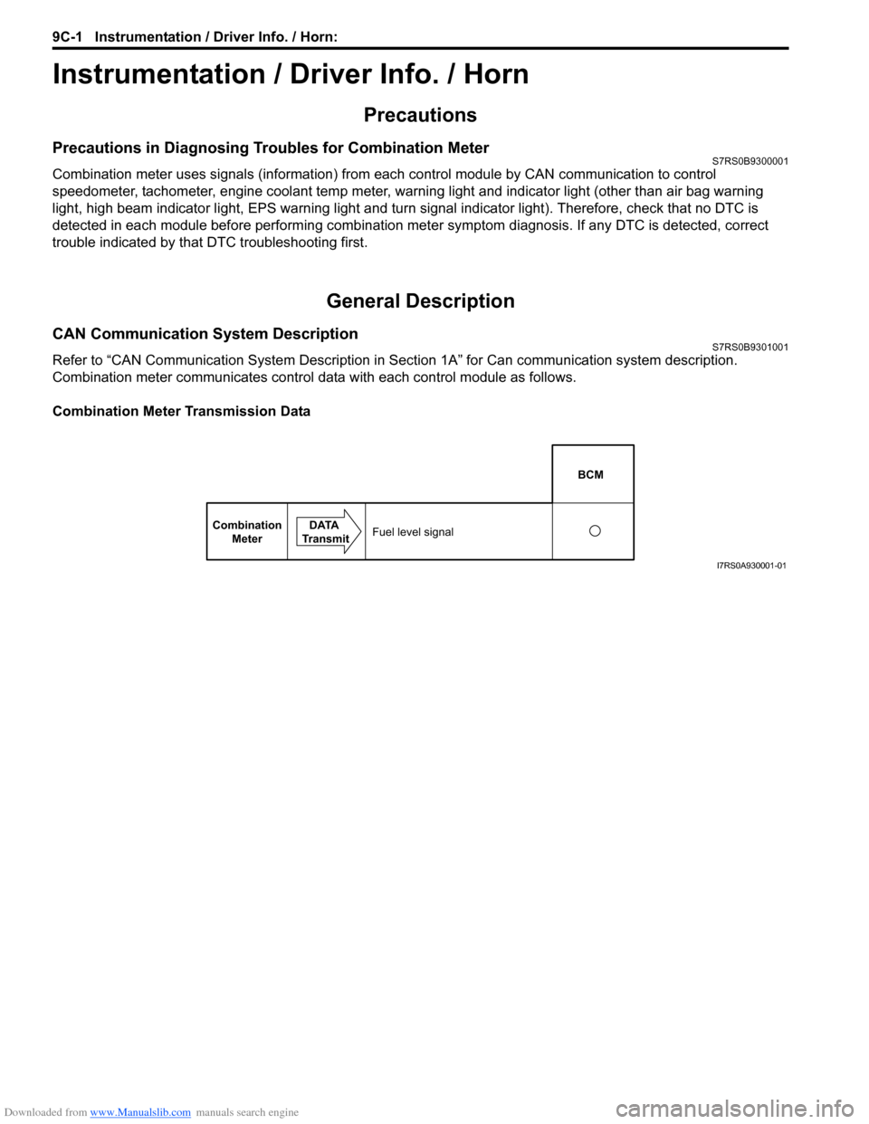
Combination meter communicates control data with each control module as follows.
Combination Meter Transmission Data
BCM
Combination Meter DATA
TransmitFuel level signal
I7RS0A930001-01