2006 SUZUKI SWIFT sound system
[x] Cancel search: sound systemPage 87 of 1496
Downloaded from www.Manualslib.com manuals search engine Engine General Information and Diagnosis: 1A-37
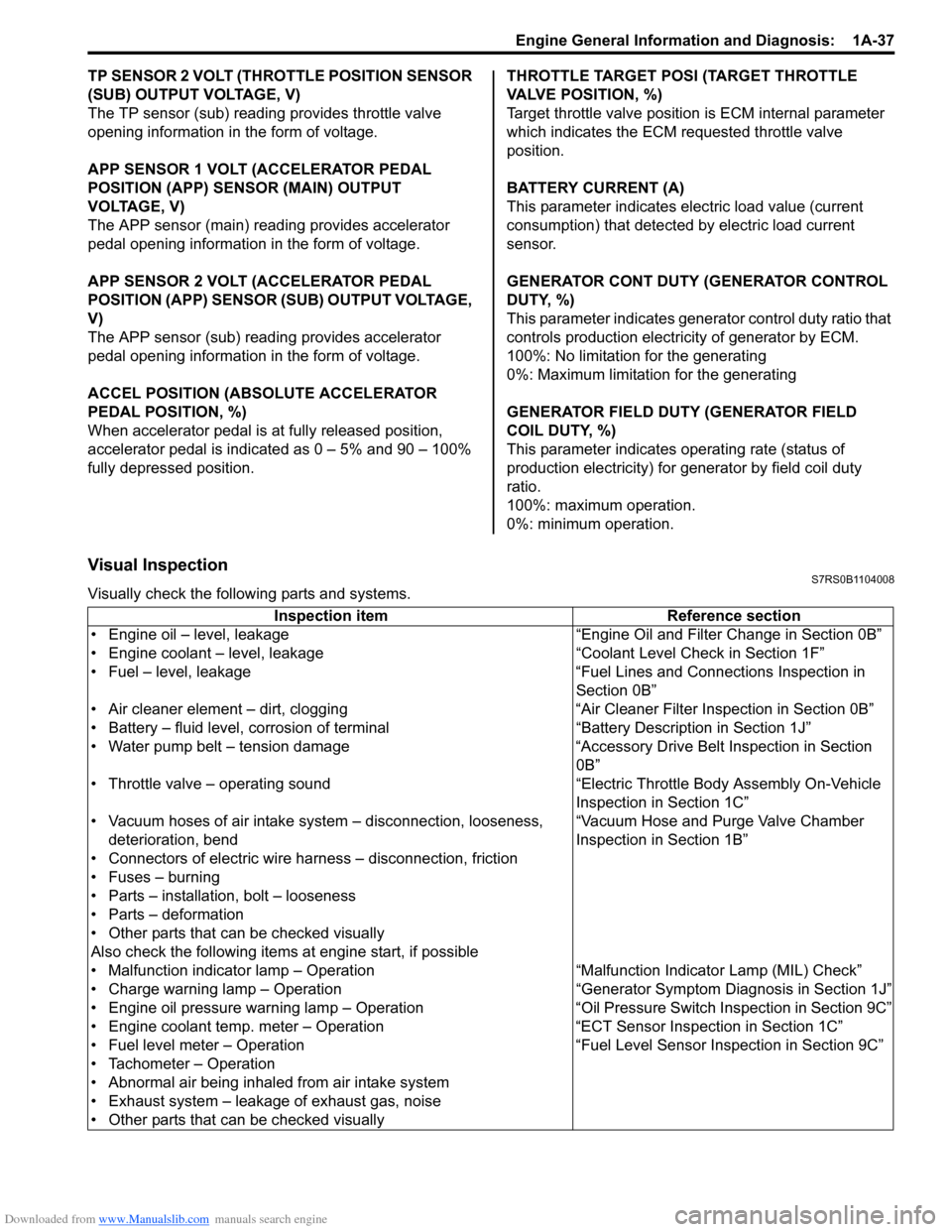
TP SENSOR 2 VOLT (THROTTLE POSITION SENSOR
(SUB) OUTPUT VOLTAGE, V)
The TP sensor (sub) reading provides throttle valve
opening information in the form of voltage.
APP SENSOR 1 VOLT (ACCELERATOR PEDAL
POSITION (APP) SENSOR (MAIN) OUTPUT
VOLTAGE, V)
The APP sensor (main) read ing provides accelerator
pedal opening information in the form of voltage.
APP SENSOR 2 VOLT (ACCELERATOR PEDAL
POSITION (APP) SENSOR (S UB) OUTPUT VOLTAGE,
V)
The APP sensor (sub) reading provides accelerator
pedal opening information in the form of voltage.
ACCEL POSITION (ABSOLUTE ACCELERATOR
PEDAL POSITION, %)
When accelerator pedal is at fully released position,
accelerator pedal is indicated as 0 – 5% and 90 – 100%
fully depressed position. THROTTLE TARGET POSI (TARGET THROTTLE
VALVE POSITION, %)
Target throttle valve position is ECM internal parameter
which indicates the ECM requested throttle valve
position.
BATTERY CURRENT (A)
This parameter indicates elec
tric load value (current
consumption) that detected by electric load current
sensor.
GENERATOR CONT DUTY (GENERATOR CONTROL
DUTY, %)
This parameter indicates generator control duty ratio that
controls production electricity of generator by ECM.
100%: No limitation for the generating
0%: Maximum limitation for the generating
GENERATOR FIELD DUTY (GENERATOR FIELD
COIL DUTY, %)
This parameter indicates ope rating rate (status of
production electricity) for gen erator by field coil duty
ratio.
100%: maximum operation.
0%: minimum operation.
Visual InspectionS7RS0B1104008
Visually check the following parts and systems.
Inspection item Reference section
• Engine oil – level, leakage “Engine Oil and Filter Change in Section 0B”
• Engine coolant – level, leakage “Co olant Level Check in Section 1F”
• Fuel – level, leakage “Fuel Lines and Connections Inspection in Section 0B”
• Air cleaner element – dirt, clogging “Air Cleaner Filter Inspection in Section 0B”
• Battery – fluid level, corrosion of terminal “Battery Description in Section 1J”
• Water pump belt – tension damage “Accessory Drive Belt Inspection in Section 0B”
• Throttle valve – operating sound “Electric Throttle Body Assembly On-Vehicle Inspection in Section 1C”
• Vacuum hoses of air intake system – disconnection, looseness,
deterioration, bend “Vacuum Hose and Purge Valve Chamber
Inspection in Section 1B”
• Connectors of electric wire harness – disconnection, friction
• Fuses – burning
• Parts – installation, bolt – looseness
• Parts – deformation
• Other parts that can be checked visually
Also check the following items at engine start, if possible
• Malfunction indicator lamp – Operation “Malfunction Indicator Lamp (MIL) Check”
• Charge warning lamp – Operation “Genera tor Symptom Diagnosis in Section 1J”
• Engine oil pressure warning lamp – Operation “O il Pressure Switch Inspection in Section 9C”
• Engine coolant temp. meter – Operation “ECT Sensor Inspection in Section 1C”
• Fuel level meter – Operation “Fuel Level Sensor Inspection in Section 9C”
• Tachometer – Operation
• Abnormal air being inhaled from air intake system
• Exhaust system – leakage of exhaust gas, noise
• Other parts that can be checked visually
Page 94 of 1496

Downloaded from www.Manualslib.com manuals search engine 1A-44 Engine General Information and Diagnosis:
Engine hesitates –
Momentary lack of
response as accelerator
is depressed. Can occur
at all vehicle speeds.
Usually most severe when
first trying to make
vehicle move, as from a
stop sign.Spark plug faulty
“Spark Plug Inspection in Section 1H”
Leaky high-tension cord “High-Tension Cord Inspection in Section 1H”
Fuel pressure out of specification “Fuel Pressure Check”
Malfunctioning EGR valve “EGR Valve Inspection in Section 1B”
Poor performance of ECT sensor or
MAF sensor “ECT Sensor Inspection in Section 1C” or
“MAF and IAT Sensor Inspection in Section
1C”
Faulty electric throttle body assembly “Electric Throttle Body Assembly On-Vehicle
Inspection in Section 1C”
Faulty APP sensor assembly “APP Sensor Assembly Inspection in Section
1C”
Faulty fuel injector “Fuel Injector Circuit Check”
Faulty ECM
Engine overheating Condition “Engine overheating”
Low compression “Compression Check in Section 1D”
Camshaft position control (VVT) system
out of order “Oil Control Valve Inspection in Section 1D”
Surge – Engine power
variation under steady
throttle or cruise. Feels
like vehicle speeds up
and down with no change
in accelerator pedal. Leaky or loosely connected high-tension
cord
“High-Tension Cord Removal and Installation
in Section 1H”
Faulty spark plug (excess carbon
deposits, improper gap, burned
electrodes, etc.) “Spark Plug Inspection in Section 1H”
Variable fuel pressure “Fuel Pressure Check”
Kinky or damaged fuel hose and lines
Faulty fuel pump (clogged fuel filter)
Malfunctioning EGR valve “EGR Valve Inspection in Section 1B”
Poor performance of MAF sensor “MAF and IAT Sensor Inspection in Section
1C”
Faulty fuel injector “Fuel Injector Circuit Check”
Faulty electric throttle body assembly “Electric Throttle Body Assembly On-Vehicle
Inspection in Section 1C”
Faulty APP sensor assembly “APP Sensor Assembly Inspection in Section
1C”
Faulty ECM
Excessive detonation –
Engine makes
continuously sharp
metallic knocks that
change with throttle
opening. Sounds like pop
corn popping. Faulty spark plug
“Spark Plug Inspection in Section 1H”
Loose connection of high-tension cord “High-Tension Cord Removal and Installation
in Section 1H”
Engine overheating Condition “Engine overheating”
Clogged fuel filter (faulty fuel pump) or
fuel lines “Fuel Pressure Check” or “Fuel Pump and Its
Circuit Check”
Air drawn in through intake manifold or
throttle body gasket
Malfunctioning EGR valve “EGR Valve Inspection in Section 1B”
Poor performance of knock sensor, ECT
sensor or MAF sensor “DTC P0327 / P0328: Knock Sensor 1 Circuit
Low / High”, “ECT Sensor Inspection in
Section 1C” or “MAF and IAT Sensor
Inspection in Section 1C”
Faulty fuel injector(s) “Fuel Injector Circuit Check”
Faulty ECM
Excessive combustion chamber
deposits “Cylinders, Pistons and Piston Rings
Inspection in Section 1D” and/or “Piston Pins
and Connecting Rods In
spection in Section
1D”
Camshaft position control (VVT) system
out of order “Oil Control Valve Inspection in Section 1D”
Condition Possible cause Correction / Reference Item
Page 156 of 1496
Downloaded from www.Manualslib.com manuals search engine 1A-106 Engine General Information and Diagnosis:
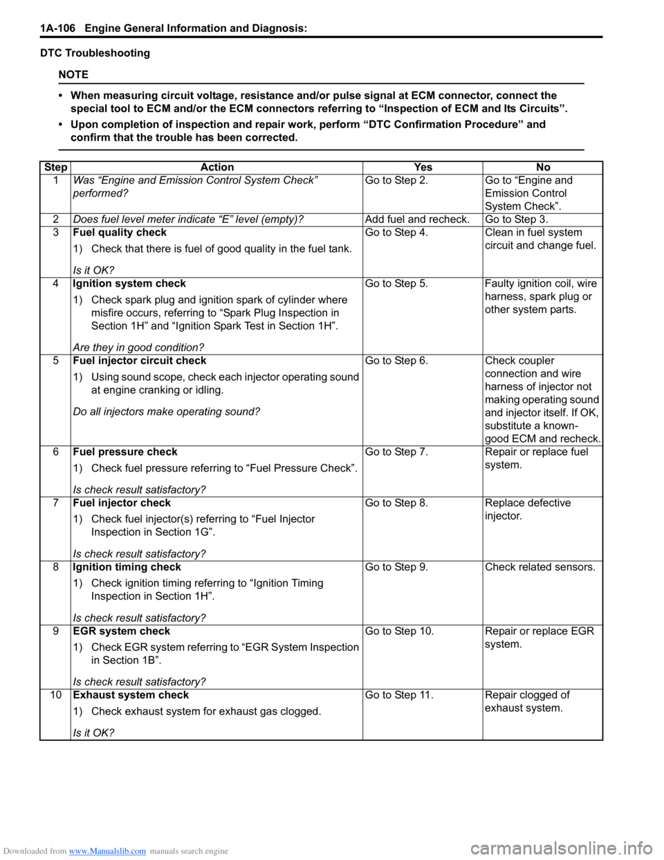
DTC Troubleshooting
NOTE
• When measuring circuit voltage, resistance and/or pulse signal at ECM connector, connect the
special tool to ECM and/or the ECM connectors re ferring to “Inspection of ECM and Its Circuits”.
• Upon completion of inspection and repair work, perform “DTC Confirmation Procedure” and confirm that the trouble has been corrected.
Step Action YesNo
1 Was “Engine and Emission Control System Check”
performed? Go to Step 2.
Go to “Engine and
Emission Control
System Check”.
2 Does fuel level meter in dicate “E” level (empty)? Add fuel and recheck. Go to Step 3.
3 Fuel quality check
1) Check that there is fuel of good quality in the fuel tank.
Is it OK? Go to Step 4.
Clean in fuel system
circuit and change fuel.
4 Ignition system check
1) Check spark plug and ignition spark of cylinder where
misfire occurs, referring to “Spark Plug Inspection in
Section 1H” and “Ignition Spark Test in Section 1H”.
Are they in good condition? Go to Step 5.
Faulty ignition coil, wire
harness, spark plug or
other system parts.
5 Fuel injector circuit check
1) Using sound scope, check each injector operating sound
at engine cranking or idling.
Do all injectors ma ke operating sound? Go to Step 6.
Check coupler
connection and wire
harness of injector not
making operating sound
and injector itself. If OK,
substitute a known-
good ECM and recheck.
6 Fuel pressure check
1) Check fuel pressure referring to “Fuel Pressure Check”.
Is check result satisfactory? Go to Step 7.
Repair or replace fuel
system.
7 Fuel injector check
1) Check fuel injector(s) re ferring to “Fuel Injector
Inspection in Section 1G”.
Is check result satisfactory? Go to Step 8.
Replace defective
injector.
8 Ignition timing check
1) Check ignition timing referring to “Ignition Timing
Inspection in Section 1H”.
Is check result satisfactory? Go to Step 9.
Check related sensors.
9 EGR system check
1) Check EGR system referring to “EGR System Inspection
in Section 1B”.
Is check result satisfactory? Go to Step 10. Repair or replace EGR
system.
10 Exhaust system check
1) Check exhaust system for exhaust gas clogged.
Is it OK? Go to Step 11. Repair clogged of
exhaust system.
Page 370 of 1496
Downloaded from www.Manualslib.com manuals search engine 1F-7 Engine Cooling System:
Cooling System Flush and RefillS7RS0B1606005
WARNING!
To help avoid danger of being burned, do not
remove radiator cap while engine and
radiator are still hot. Scalding fluid and steam
can be blown out under pressure if cap is
taken off too soon.
NOTE
For detail of coolant specification, refer to
“Coolant Description”.
1) Remove radiator cap when engine is cool as follows.a) Turn cap counterclockwise slowly until it reaches a “stop” (Do not press down while turning it).
b) Wait until pressure is relieved (indicated by a hissing sound) then press down on cap and
continue to turn it counterclockwise.
2) With radiator cap removed, run engine until upper radiator hose is hot (this shows that thermostat is
open and coolant is flowing through system).
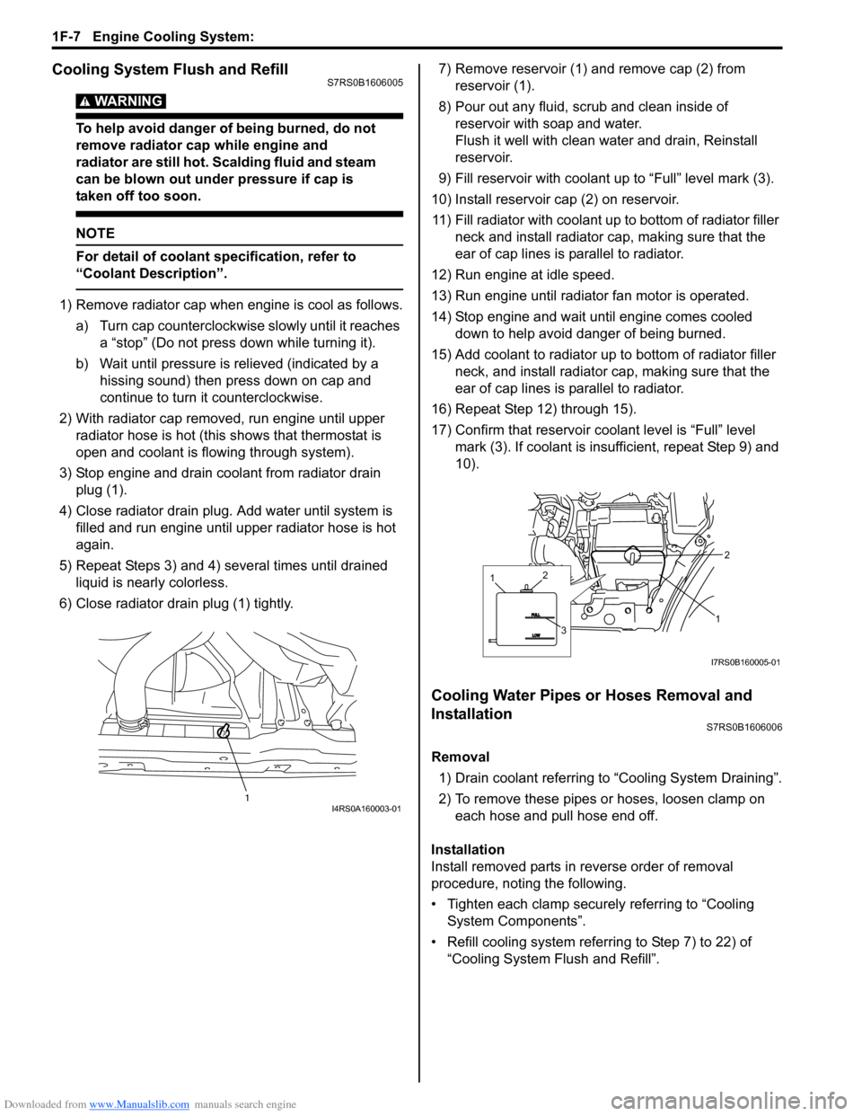
3) Stop engine and drain coolant from radiator drain plug (1).
4) Close radiator drain plug. Add water until system is filled and run engine until up per radiator hose is hot
again.
5) Repeat Steps 3) and 4) several times until drained liquid is nearly colorless.
6) Close radiator drain plug (1) tightly. 7) Remove reservoir (1) and remove cap (2) from
reservoir (1).
8) Pour out any fluid, scrub and clean inside of reservoir with soap and water.
Flush it well with clean water and drain, Reinstall
reservoir.
9) Fill reservoir with coolant up to “Full” level mark (3).
10) Install reservoir cap (2) on reservoir. 11) Fill radiator with coolant up to bottom of radiator filler neck and install radiator cap, making sure that the
ear of cap lines is parallel to radiator.
12) Run engine at idle speed.
13) Run engine until radiator fan motor is operated.
14) Stop engine and wait until engine comes cooled down to help avoid danger of being burned.
15) Add coolant to radiator up to bottom of radiator filler
neck, and install radiator ca p, making sure that the
ear of cap lines is parallel to radiator.
16) Repeat Step 12) through 15).
17) Confirm that reservoir cool ant level is “Full” level
mark (3). If coolant is insu fficient, repeat Step 9) and
10).
Cooling Water Pipes or Hoses Removal and
Installation
S7RS0B1606006
Removal
1) Drain coolant referring to “Cooling System Draining”.
2) To remove these pipes or hoses, loosen clamp on each hose and pull hose end off.
Installation
Install removed parts in reverse order of removal
procedure, noting the following.
• Tighten each clamp securely referring to “Cooling System Components”.
• Refill cooling system referrin g to Step 7) to 22) of
“Cooling System Flush and Refill”.
1I4RS0A160003-01
1
2
1
3
2
I7RS0B160005-01
Page 378 of 1496
Downloaded from www.Manualslib.com manuals search engine 1G-3 Fuel System:
4) Check that battery voltage is 11 V or more.
5) Measure fuel pressure at each condition.If measured pressure is out of specification, refer to
“Fuel Pressure Check in Section 1A” and check each
possibly defective part. Replace if found defective.
a) Turn ignition switch ON to operate fuel pump and after 2 seconds turn it OFF. Repeat this 3 or 4
times and then check fuel pressure.
Fuel pressure specification
With fuel pump operating and engine
stopped: 270 – 310 kPa (2.7 – 3.1 kg/cm2, 38.4
– 44.0 psi)
b) Start engine and warm it up to normal operating temperature, and measure fuel pressure at
idling.
Fuel pressure specification
At specified idle speed: 270 – 310 kPa (2.7 –
3.1 kg/cm2, 38.4 – 44.0 psi)
c) Stop engine, and measure fuel pressure at one minute after stopping.
Fuel pressure specification
With 1 min. after engine (fuel pump) stop
(Pressure reduces as time passes): Over 300
kPa (3.0 kg/cm
2, 42.7 psi)
6) After checking fuel pressure, remove fuel pressure gauge.
WARNING!
As fuel feed line is still under high fuel
pressure, make sure to release fuel pressure
according to the following procedures.
• Place fuel container under joint.
• Cover joint with rag and loosen joint nut slowly in order to release fuel pressure
gradually.
7) Remove special tools from fuel delivery pipe and fuel feed hose.
8) Connect fuel feed hose to fuel delivery pipe and clamp it securely.
9) With engine OFF and ignition switch ON, check for fuel leaks.
Fuel Cut Operation InspectionS7RS0B1704002
NOTE
Before inspection, make sure that gear shift
lever is in neutral positi on (shift select lever
is “P” range for A/T vehicle), A/C is OFF and
parking brake lever is pulled all the way up.
1) Warm engine up to normal operating temperature.
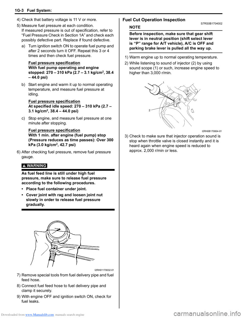
2) While listening to sound of injector (2) by using sound scope (1) or such, increase engine speed to
higher than 3,000 r/min.
3) Check to make sure that injector operation sound is stop when throttle valve is closed instantly and it is
heard again when engine speed is reduced to
approx. 2,000 r/min or less.
I2RH01170032-01
I2RH0B170004-01
Page 383 of 1496
Downloaded from www.Manualslib.com manuals search engine Fuel System: 1G-8
Installation1) Install clamps to marked location on pipes. If clamp is deformed, its claw is bent or broken, replace it with
new one.
2) Install pipes with pipe clamps to vehicle.
3) Connect fuel hoses and pipes to each pipe referring to “Fuel Hose Disconnecting and Reconnecting”.
4) Connect negative cable at battery.
5) With engine OFF, turn igniti on switch to ON position
and check for fuel leaks.
Fuel Injector On-Vehicle InspectionS7RS0B1706007
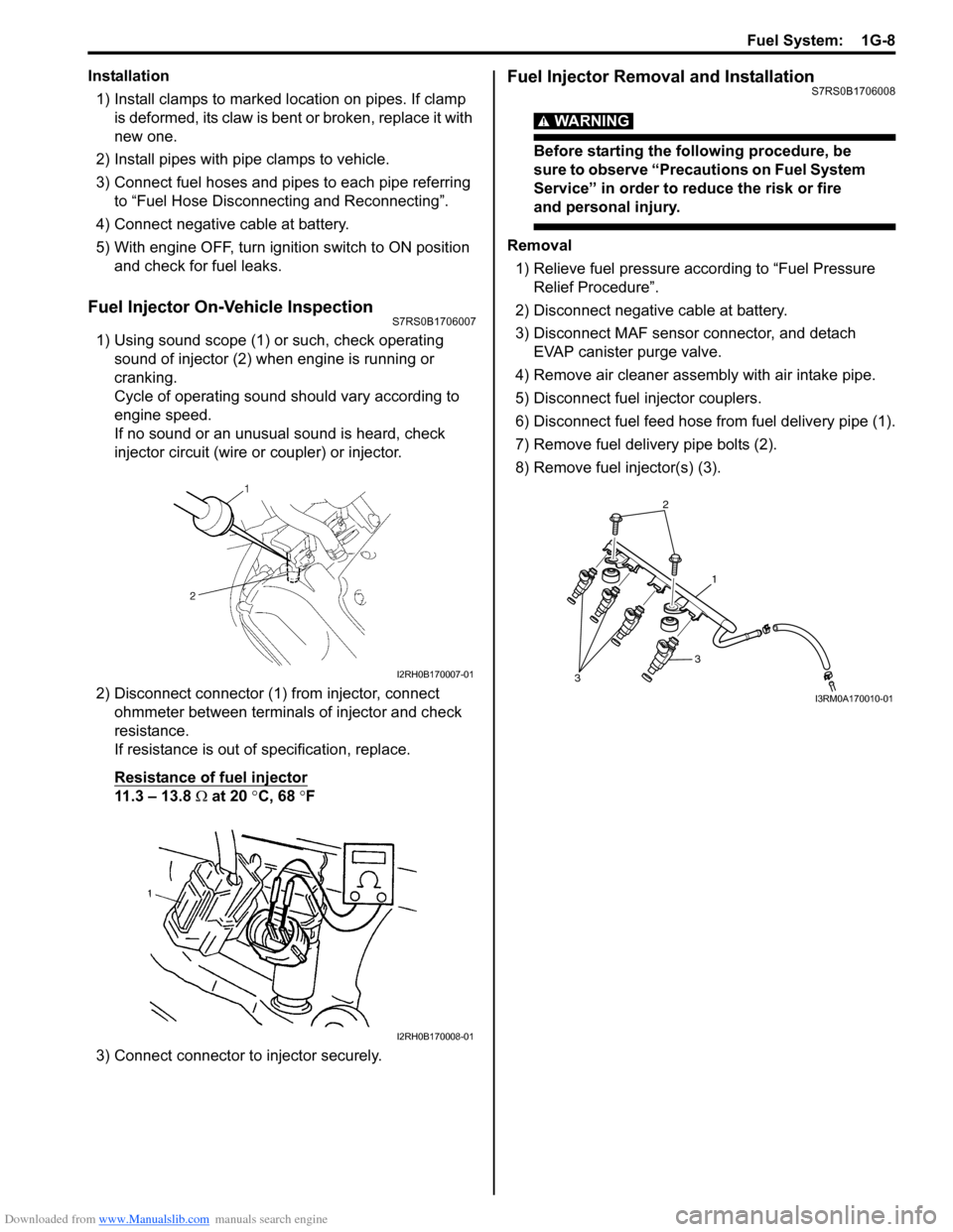
1) Using sound scope (1) or such, check operating sound of injector (2) when engine is running or
cranking.
Cycle of operating sound should vary according to
engine speed.
If no sound or an unusual sound is heard, check
injector circuit (wire or coupler) or injector.
2) Disconnect connector (1) from injector, connect ohmmeter between terminals of injector and check
resistance.
If resistance is out of specification, replace.
Resistance of fuel injector
11.3 – 13.8 Ω at 20 °C, 68 °F
3) Connect connector to injector securely.
Fuel Injector Removal and InstallationS7RS0B1706008
WARNING!
Before starting the following procedure, be
sure to observe “Precautions on Fuel System
Service” in order to reduce the risk or fire
and personal injury.
Removal 1) Relieve fuel pressure according to “Fuel Pressure Relief Procedure”.
2) Disconnect negative cable at battery.
3) Disconnect MAF sensor connector, and detach EVAP canister purge valve.
4) Remove air cleaner assembly with air intake pipe.
5) Disconnect fuel injector couplers.
6) Disconnect fuel feed hose from fuel delivery pipe (1).
7) Remove fuel delivery pipe bolts (2).
8) Remove fuel injector(s) (3).
I2RH0B170007-01
I2RH0B170008-01
2
1
3
3
I3RM0A170010-01
Page 389 of 1496

Downloaded from www.Manualslib.com manuals search engine Fuel System: 1G-14
Fuel Tank Purging ProcedureS7RS0B1706015
WARNING!
• Before starting the following procedure, be sure to observe “Precautions on Fuel
System Service” in order to reduce the risk
or fire and personal injury.
• This purging procedure will not remove all fuel vapor.
Do not attempt any repair on tank using
heat of flame as an explosion resulting in
personal injury could occur.
CAUTION!
Never remain water in fu el tank after washing,
or fuel tank inside will get corrosion.
The following procedure are used for purging fuel tank.
1) After removing fuel tank, remove all hoses, pipes and fuel pump assembly from fuel tank.
2) Drain all remaining fuel from tank.
3) Place fuel tank to flushing area.
4) Fill tank with warm water or tap water, and agitate
vigorously and drain. Repeat this washing until
inside of tank is clean. Replace tank if its inside is
rusty.
5) Completely flush out rema ining water after washing.
Fuel Pump On-Vehicle InspectionS7RS0B1706016
WARNING!
Before starting the following procedure, be
sure to observe “Precautions on Fuel System
Service” in order to reduce the risk or fire
and personal injury.
NOTE
The fuel pressure regulator is incorporated
with the fuel pump assembly so individual
inspection of it is impossible.
1) Remove filler cap and turn ON ignition switch (2).
Then fuel pump operating sound should be heard
from fuel filler (1) for about 2 seconds and stop. Be
sure to reinstall fuel filler cap after checking.
If the check result is not satisfactory, go to “Fuel
Pump and Its Circuit Check in Section 1A”. 2) Turn OFF ignition switch and leave over 10 minutes
as it is.
3) Fuel pressure should be felt at fuel feed hose (1) for about 2 seconds after ignition switch ON.
If fuel pressure is not felt, go to “Fuel Pressure
Check in Section 1A”.
Fuel Pump Assembly Removal and InstallationS7RS0B1706017
WARNING!
Before starting the following procedure, be
sure to observe “Precautions on Fuel System
Service” in order to reduce the risk or fire
and personal injury.
Removal
1) Remove fuel tank from vehicle. Refer to “Fuel Tank Removal and Installation”.
2) Disconnect fuel feed pipe (1) from fuel pump assembly (2) referring to “Fuel Hose Disconnecting
and Reconnecting”.
IVSY01170013-01
1I3RM0A170019-01
1
2
I6RS0C170008-02
Page 403 of 1496
Downloaded from www.Manualslib.com manuals search engine Starting System: 1I-2
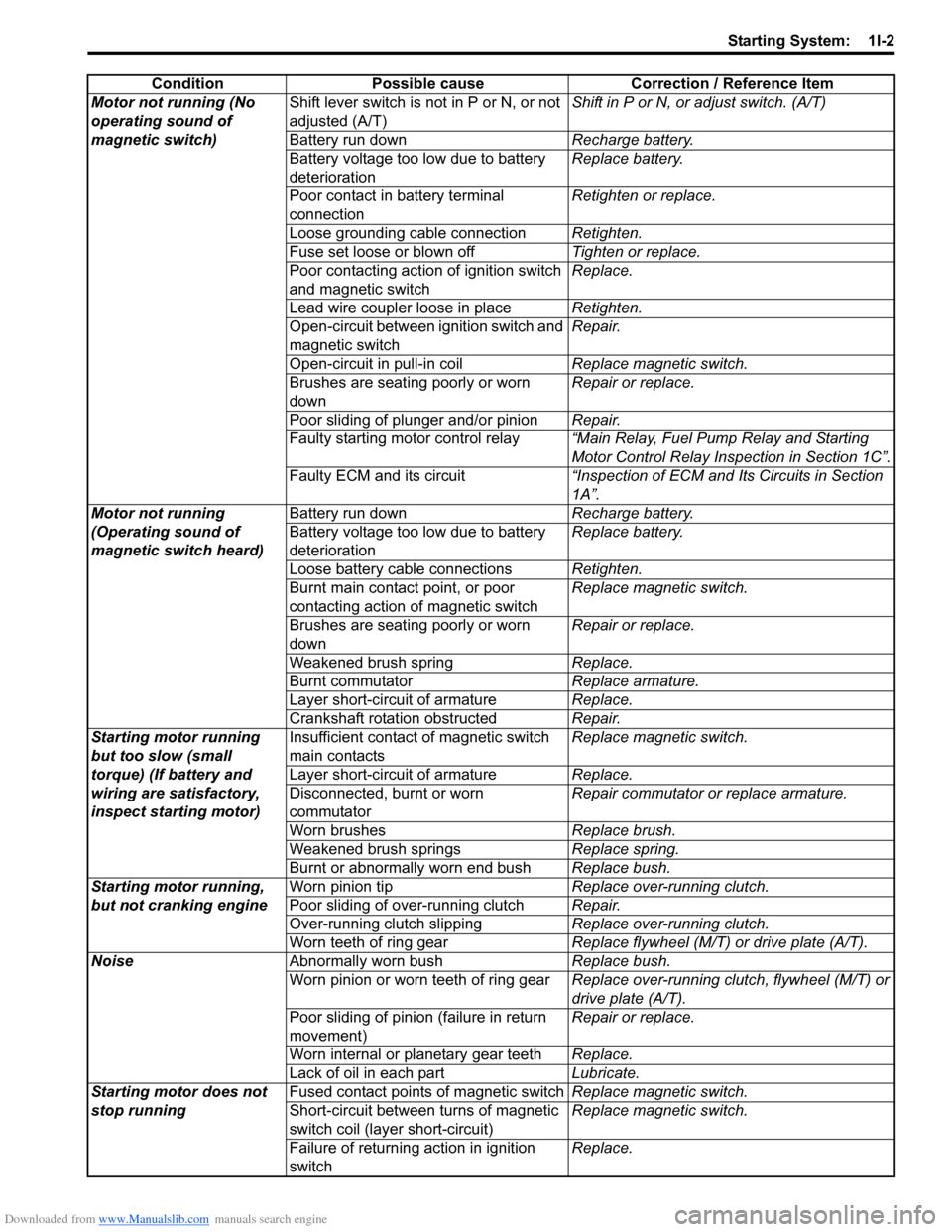
ConditionPossible cause Correction / Reference Item
Motor not running (No
operating sound of
magnetic switch) Shift lever switch is not in P or N, or not
adjusted (A/T)
Shift in P or N, or
adjust switch. (A/T)
Battery run down Recharge battery.
Battery voltage too low due to battery
deterioration Replace battery.
Poor contact in battery terminal
connection Retighten or replace.
Loose grounding cable connection Retighten.
Fuse set loose or blown off Tighten or replace.
Poor contacting action of ignition switch
and magnetic switch Replace.
Lead wire coupler loose in place Retighten.
Open-circuit between ignition switch and
magnetic switch Repair.
Open-circuit in pull-in coil Replace magnetic switch.
Brushes are seating poorly or worn
down Repair or replace.
Poor sliding of plunger and/or pinion Repair.
Faulty starting motor control relay “Main Relay, Fuel Pump Relay and Starting
Motor Control Relay Inspection in Section 1C”.
Faulty ECM and its circuit “Inspection of ECM and Its Circuits in Section
1A”.
Motor not running
(Operating sound of
magnetic switch heard) Battery run down
Recharge battery.
Battery voltage too low due to battery
deterioration Replace battery.
Loose battery cable connections Retighten.
Burnt main contact point, or poor
contacting action of magnetic switch Replace magnetic switch.
Brushes are seating poorly or worn
down Repair or replace.
Weakened brush spring Replace.
Burnt commutator Replace armature.
Layer short-circuit of armature Replace.
Crankshaft rotation obstructed Repair.
Starting motor running
but too slow (small
torque) (If battery and
wiring are satisfactory,
inspect starting motor) Insufficient contact
of magnetic switch
main contacts Replace magnetic switch.
Layer short-circuit of armature Replace.
Disconnected, burnt or worn
commutator Repair commutator or replace armature.
Worn brushes Replace brush.
Weakened brush springs Replace spring.
Burnt or abnormally worn end bush Replace bush.
Starting motor running,
but not cranking engine Worn pinion tip
Replace over-running clutch.
Poor sliding of over-running clutch Repair.
Over-running clutch slipping Replace over-running clutch.
Worn teeth of ring gear Replace flywheel (M/T) or drive plate (A/T).
Noise Abnormally worn bush Replace bush.
Worn pinion or worn teeth of ring gear Replace over-running clutch, flywheel (M/T) or
drive plate (A/T).
Poor sliding of pinion (failure in return
movement) Repair or replace.
Worn internal or planetary gear teeth Replace.
Lack of oil in each part Lubricate.
Starting motor does not
stop running Fused contact points of magnetic switch
Replace magnetic switch.
Short-circuit between turns of magnetic
switch coil (layer short-circuit) Replace magnetic switch.
Failure of returning action in ignition
switch Replace.