2006 SUZUKI SWIFT wire diagram
[x] Cancel search: wire diagramPage 172 of 1496
Downloaded from www.Manualslib.com manuals search engine 1A-122 Engine General Information and Diagnosis:
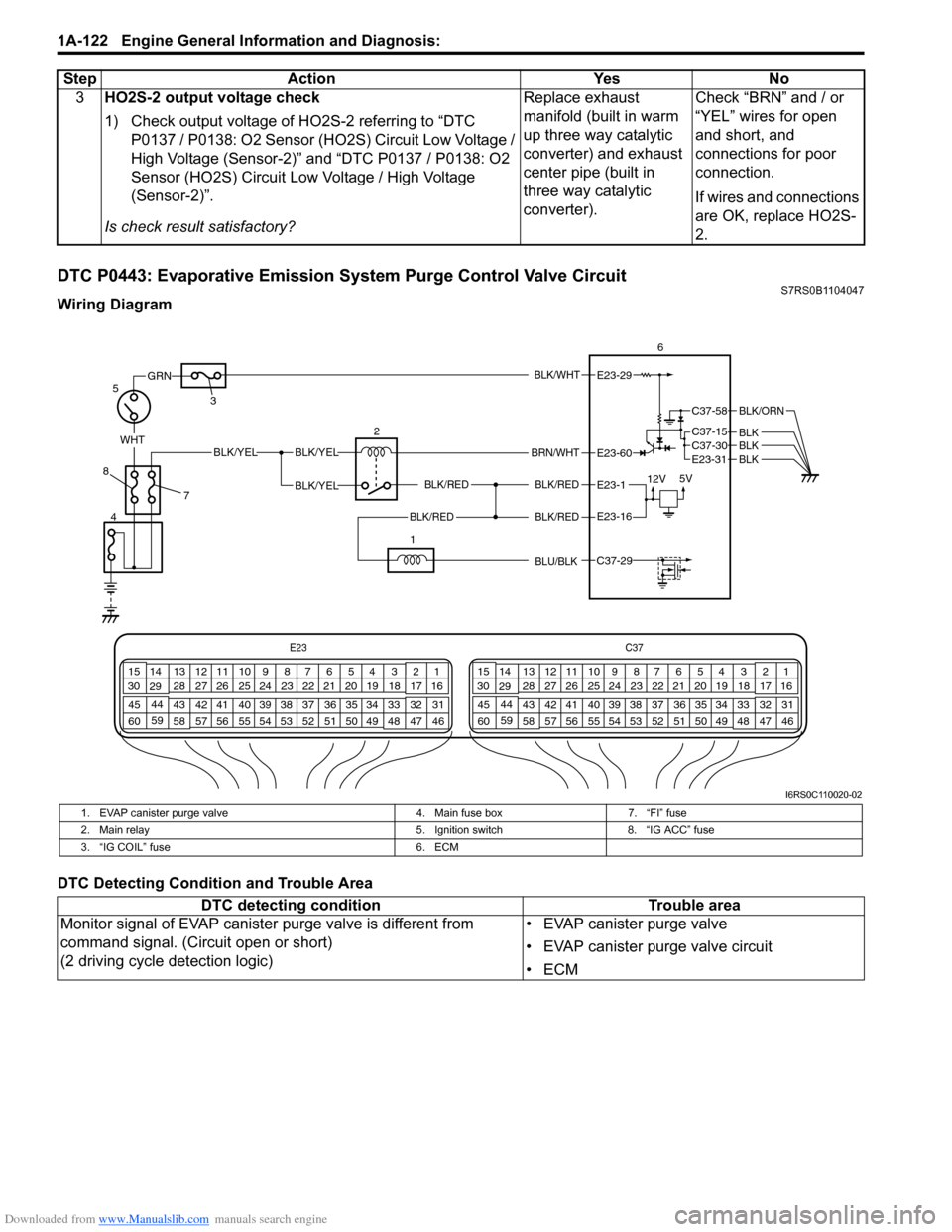
DTC P0443: Evaporative Emission System Purge Control Valve CircuitS7RS0B1104047
Wiring Diagram
DTC Detecting Condition and Trouble Area3
HO2S-2 output voltage check
1) Check output voltage of HO2S-2 referring to “DTC
P0137 / P0138: O2 Sensor (HO2S) Circuit Low Voltage /
High Voltage (Sensor-2)” and “DTC P0137 / P0138: O2
Sensor (HO2S) Circuit Low Voltage / High Voltage
(Sensor-2)”.
Is check result satisfactory? Replace exhaust
manifold (built in warm
up three way catalytic
converter) and exhaust
center pipe (built in
three way catalytic
converter).
Check “BRN” and / or
“YEL” wires for open
and short, and
connections for poor
connection.
If wires and connections
are OK, replace HO2S-
2.
Step Action Yes No
E23
C37
34
1819
567
1011
17
20
47 46
495051
2122
52 16
25 9
24
14
29
55
57 54 53
59
60 58 2
262728
15
30
56 4832 31
34353637
40
42 39 38
44
45 43 41 33 1
1213
238
34
1819
567
1011
17
20
47 46
495051
2122
52 16
25 9
24
14
29
55
57 54 53
59
60 58 2
262728
15
30
56 48 32 31
34353637
40
42 39 38
44
45 43 41 331
1213
238
BLK/WHT
BLK/RED
BLK/RED
WHTBLK/YELBLK/YEL
BLK/YEL
GRN
BRN/WHT
12V 5V
5
4 2
3 6E23-29
E23-1
E23-60
C37-58
C37-15 C37-30
BLK/ORN
BLKBLKE23-31 BLK
7
8
BLK/REDBLK/REDE23-16
1
C37-29 BLU/BLK
I6RS0C110020-02
1. EVAP canister purge valve
4. Main fuse box7. “FI” fuse
2. Main relay 5. Ignition switch8. “IG ACC” fuse
3. “IG COIL” fuse 6. ECM
DTC detecting conditionTrouble area
Monitor signal of EVAP canister purge valve is different from
command signal. (Circuit open or short)
(2 driving cycle detection logic) • EVAP canister purge valve
• EVAP canister purge valve circuit
•ECM
Page 174 of 1496
Downloaded from www.Manualslib.com manuals search engine 1A-124 Engine General Information and Diagnosis:
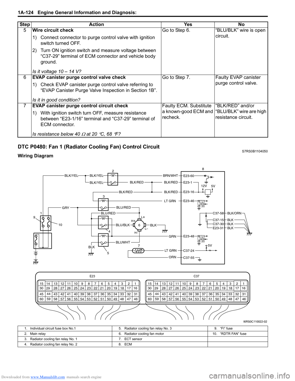
DTC P0480: Fan 1 (Radiator Cooling Fan) Control CircuitS7RS0B1104050
Wiring Diagram5
Wire circuit check
1) Connect connector to purge control valve with ignition
switch turned OFF.
2) Turn ON ignition switch and measure voltage between “C37-29” terminal of ECM connector and vehicle body
ground.
Is it voltage 10 – 14 V? Go to Step 6. “BLU/BLK” wire is open
circuit.
6 EVAP canister purge control valve check
1) Check EVAP canister purge control valve referring to
“EVAP Canister Purge Valve Inspection in Section 1B”.
Is it in good condition? Go to Step 7. Faulty EVAP canister
purge control valve.
7 EVAP canister purge control circuit check
1) With ignition switch turn OFF, measure resistance
between “E23-1/16” terminal and “C37-29” terminal of
ECM connector.
Is resistance below 40
Ω at 20 °C, 68 °F? Faulty ECM. Substitute
a known-good ECM and
recheck.
“BLK/RED” and/or
“BLU/BLK” wire are high
resistance circuit.
Step Action Yes No
E23
C37
34
1819
567
1011
17
20
47 46
495051
2122
52 16
25 9
24
14
29
55
57 54 53
59
60 58 2
262728
15
30
56 4832 31
34353637
40
42 39 38
44
45 43 41 331
1213
238
34
1819
567
1011
17
20
47 46
495051
2122
52 16
25 9
24
14
29
55
57 54 53
59
60 58 2
262728
15
30
56 4832 31
34353637
40
42 39 38
44
45 43 41 331
1213
238
BLK/REDBLK/RED
BLK/YELBLK/YEL
BLK/YEL
BRN/WHT
12V
5V5V
2
8
E23-1
E23-60
C37-58
C37-15 C37-30
BLK/ORN
BLKBLKE23-31BLK
BLK/RED
LT GRN
BLK/REDE23-16
E23-46
L+
L–
H–
H
+
BLU/RED
BLK
BLUWHTBLK
BLU/BLK
BLU/RED
4
GRN
GRY
E23-48
LT GRN
ORN
C37-24
C37-55
35
6
7
10
9
1
I6RS0C110022-02
1. Individual circuit fuse box No.1
5. Radiator cooling fan relay No. 3 9. “FI” fuse
2. Main relay 6. Radiator cooling fan motor10. “RDTR FAN” fuse
3. Radiator cooling fan relay No. 1 7. ECT sensor
4. Radiator cooling fan relay No. 2 8. ECM
Page 178 of 1496
Downloaded from www.Manualslib.com manuals search engine 1A-128 Engine General Information and Diagnosis:
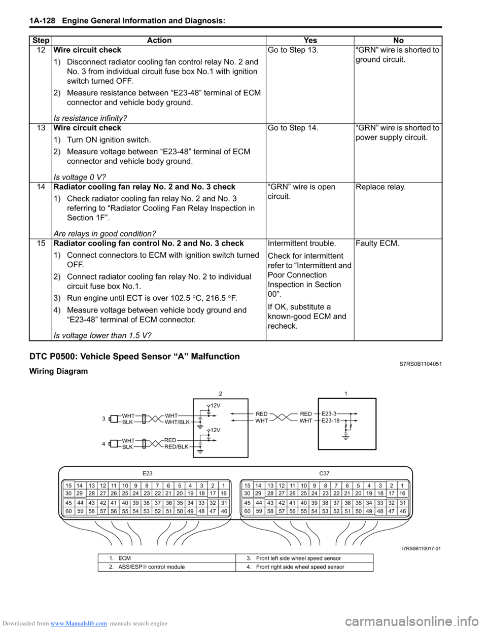
DTC P0500: Vehicle Speed Sensor “A” MalfunctionS7RS0B1104051
Wiring Diagram12
Wire circuit check
1) Disconnect radiator cooling fan control relay No. 2 and
No. 3 from individual circuit fuse box No.1 with ignition
switch turned OFF.
2) Measure resistance between “E23-48” terminal of ECM connector and vehicle body ground.
Is resistance infinity? Go to Step 13. “GRN” wire is shorted to
ground circuit.
13 Wire circuit check
1) Turn ON ignition switch.
2) Measure voltage between “E23-48” terminal of ECM
connector and vehicle body ground.
Is voltage 0 V? Go to Step 14. “GRN” wire is shorted to
power supply circuit.
14 Radiator cooling fan relay No. 2 and No. 3 check
1) Check radiator cooling fan relay No. 2 and No. 3
referring to “Radiator Coolin g Fan Relay Inspection in
Section 1F”.
Are relays in good condition? “GRN” wire is open
circuit.
Replace relay.
15 Radiator cooling fan control No. 2 and No. 3 check
1) Connect connectors to ECM with ignition switch turned
OFF.
2) Connect radiator cooling fan relay No. 2 to individual circuit fuse box No.1.
3) Run engine until ECT is over 102.5 °C, 216.5 °F.
4) Measure voltage between vehicle body ground and “E23-48” terminal of ECM connector.
Is voltage lower than 1.5 V? Intermittent trouble.
Check for intermittent
refer to “Intermittent and
Poor Connection
Inspection in Section
00”.
If OK, substitute a
known-good ECM and
recheck.
Faulty ECM.
Step Action Yes No
E23
C37
34
1819
567
10
11
17
20
47 46
495051
2122
52 16
25 9
24
14
29
55
57 54 53
59
60 58 2
262728
15
30
56 4832 31
34353637
40
42 39 38
44
45 43 41 331
1213
238
34
1819
567
10
11
17
20
47 46
495051
2122
52 16
25 9
24
14
29
55
57 54 53
59
60 58 2
262728
15
30
56 4832 31
34353637
40
42 39 38
44
45 43 41 331
1213
238
E23-3E23-18REDWHTREDWHTWHT/BLKWHTBLKWHT
BLKWHTREDRED/BLK
12V
12V
3
4 21
I7RS0B110017-01
1. ECM
3. Front left side wheel speed sensor
2. ABS/ESP® control module 4. Front right side wheel speed sensor
Page 182 of 1496
Downloaded from www.Manualslib.com manuals search engine 1A-132 Engine General Information and Diagnosis:
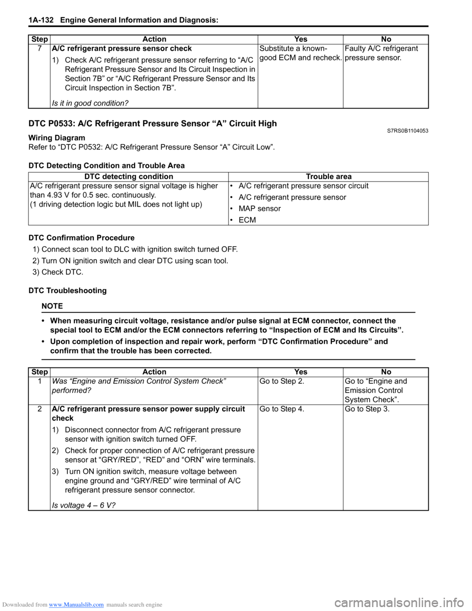
DTC P0533: A/C Refrigerant Pressure Sensor “A” Circuit HighS7RS0B1104053
Wiring Diagram
Refer to “DTC P0532: A/C Refrigerant Pressure Sensor “A” Circuit Low”.
DTC Detecting Condition and Trouble Area
DTC Confirmation Procedure1) Connect scan tool to DLC with ignition switch turned OFF.
2) Turn ON ignition switch and clear DTC using scan tool.
3) Check DTC.
DTC Troubleshooting
NOTE
• When measuring circuit voltage, resistance and/ or pulse signal at ECM connector, connect the
special tool to ECM and/or the ECM connectors re ferring to “Inspection of ECM and Its Circuits”.
• Upon completion of inspection and repair work, perform “DTC Confirmation Procedure” and confirm that the trouble has been corrected.
7 A/C refrigerant pressure sensor check
1) Check A/C refrigerant pressure sensor referring to “A/C
Refrigerant Pressure Sensor and Its Circuit Inspection in
Section 7B” or “A/C Refrigerant Pressure Sensor and Its
Circuit Inspection in Section 7B”.
Is it in good condition? Substitute a known-
good ECM and recheck.
Faulty A/C refrigerant
pressure sensor.
Step Action Yes No
DTC detecting condition
Trouble area
A/C refrigerant pressure sensor signal voltage is higher
than 4.93 V for 0.5 sec. continuously.
(1 driving detection logic but MIL does not light up) • A/C refrigerant pressure sensor circuit
• A/C refrigerant pressure sensor
• MAP sensor
•ECM
Step
Action YesNo
1 Was “Engine and Emission Control System Check”
performed? Go to Step 2.
Go to “Engine and
Emission Control
System Check”.
2 A/C refrigerant pressure sensor power supply circuit
check
1) Disconnect connector from A/C refrigerant pressure
sensor with ignition switch turned OFF.
2) Check for proper connection of A/C refrigerant pressure sensor at “GRY/RED”, “RED ” and “ORN” wire terminals.
3) Turn ON ignition switch, measure voltage between engine ground and “GRY/RED” wire terminal of A/C
refrigerant pressure sensor connector.
Is voltage 4 – 6 V? Go to Step 4.
Go to Step 3.
Page 186 of 1496
Downloaded from www.Manualslib.com manuals search engine 1A-136 Engine General Information and Diagnosis:
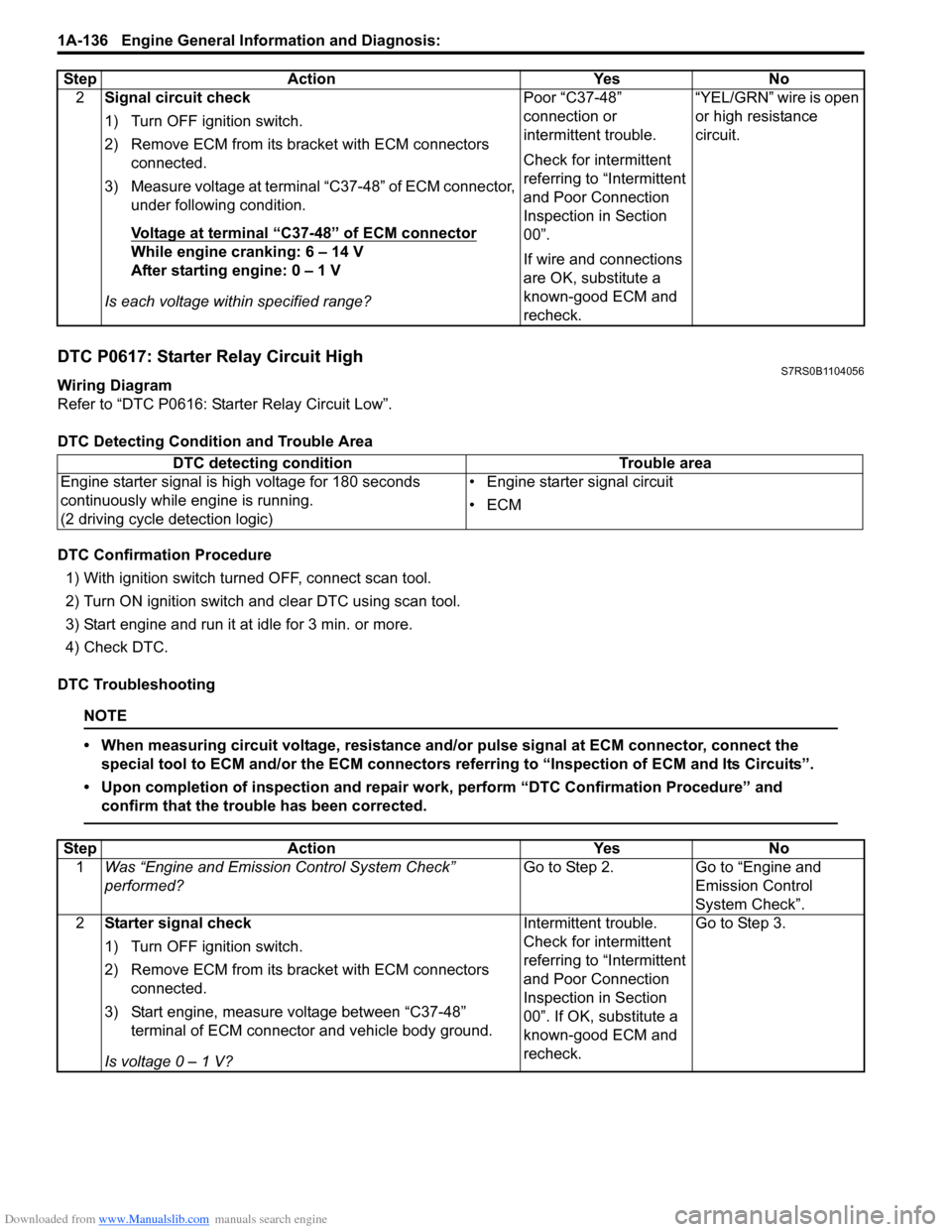
DTC P0617: Starter Relay Circuit HighS7RS0B1104056
Wiring Diagram
Refer to “DTC P0616: Starter Relay Circuit Low”.
DTC Detecting Condition and Trouble Area
DTC Confirmation Procedure1) With ignition switch turned OFF, connect scan tool.
2) Turn ON ignition switch and clear DTC using scan tool.
3) Start engine and run it at idle for 3 min. or more.
4) Check DTC.
DTC Troubleshooting
NOTE
• When measuring circuit voltage, resistance and/ or pulse signal at ECM connector, connect the
special tool to ECM and/or the ECM connectors re ferring to “Inspection of ECM and Its Circuits”.
• Upon completion of inspection and repair work, perform “DTC Confirmation Procedure” and confirm that the trouble has been corrected.
2 Signal circuit check
1) Turn OFF ignition switch.
2) Remove ECM from its br acket with ECM connectors
connected.
3) Measure voltage at terminal “C37-48” of ECM connector, under following condition.
Voltage at terminal “C37-48” of ECM connector
While engine cranking: 6 – 14 V
After starting engine: 0 – 1 V
Is each voltage within specified range? Poor “C37-48”
connection or
intermittent trouble.
Check for intermittent
referring to “Intermittent
and Poor Connection
Inspection in Section
00”.
If wire and connections
are OK, substitute a
known-good ECM and
recheck.“YEL/GRN” wire is open
or high resistance
circuit.
Step Action Yes No
DTC detecting condition
Trouble area
Engine starter signal is high voltage for 180 seconds
continuously while engine is running.
(2 driving cycle detection logic) • Engine starter signal circuit
•ECM
Step
Action YesNo
1 Was “Engine and Emission Control System Check”
performed? Go to Step 2.
Go to “Engine and
Emission Control
System Check”.
2 Starter signal check
1) Turn OFF ignition switch.
2) Remove ECM from its br acket with ECM connectors
connected.
3) Start engine, measure voltage between “C37-48” terminal of ECM connector and vehicle body ground.
Is voltage 0 – 1 V? Intermittent trouble.
Check for intermittent
referring to “Intermittent
and Poor Connection
Inspection in Section
00”. If OK, substitute a
known-good ECM and
recheck.
Go to Step 3.
Page 187 of 1496
Downloaded from www.Manualslib.com manuals search engine Engine General Information and Diagnosis: 1A-137
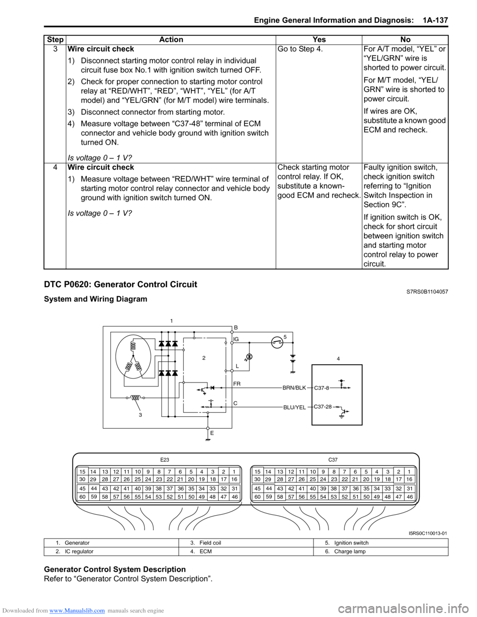
DTC P0620: Generator Control CircuitS7RS0B1104057
System and Wiring Diagram
Generator Control System Description
Refer to “Generator Control System Description”.3
Wire circuit check
1) Disconnect starting motor control relay in individual
circuit fuse box No.1 with ignition switch turned OFF.
2) Check for proper connection to starting motor control relay at “RED/WHT”, “RED”, “WHT”, “YEL” (for A/T
model) and “YEL/GRN” (for M/T model) wire terminals.
3) Disconnect connector from starting motor.
4) Measure voltage between “C37-48” terminal of ECM connector and vehicle body ground with ignition switch
turned ON.
Is voltage 0 – 1 V? Go to Step 4. For A/T model, “YEL” or
“YEL/GRN” wire is
shorted to power circuit.
For M/T model, “YEL/
GRN” wire is shorted to
power circuit.
If wires are OK,
substitute a known good
ECM and recheck.
4 Wire circuit check
1) Measure voltage between “RED/WHT” wire terminal of
starting motor control relay connector and vehicle body
ground with ignition switch turned ON.
Is voltage 0 – 1 V? Check starting motor
control relay. If OK,
substitute a known-
good ECM and recheck.
Faulty ignition switch,
check ignition switch
referring to “Ignition
Switch Inspection in
Section 9C”.
If ignition switch is OK,
check for short circuit
between ignition switch
and starting motor
control relay to power
circuit.
Step Action Yes No
IG
L
C
FR
E 4
2
BRN/BLKC37-8
BLU/YELC37-28
B
E23
C37
34
1819
567
1011
17
20
47 46
495051
2122
52 16
25 9
24
14
29
55
57 54 53
59
60 58 2
262728
15
30
56 4832 31
34353637
40
42 39 38
44
45 43 41 331
1213
238
34
1819
567
1011
17
20
47 46
495051
2122
52 16
25 9
24
14
29
55
57 54 53
59
60 58 2
262728
15
30
56 4832 31
34353637
40
42 39 38
44
45 43 41 331
1213
238 1
3 5
I5RS0C110013-01
1. Generator
3. Field coil 5. Ignition switch
2. IC regulator 4. ECM 6. Charge lamp
Page 189 of 1496
Downloaded from www.Manualslib.com manuals search engine Engine General Information and Diagnosis: 1A-139
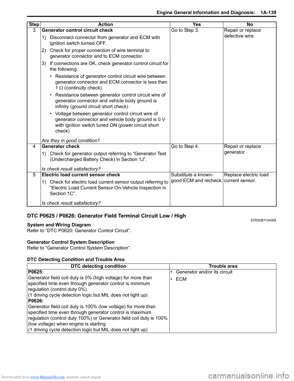
DTC P0625 / P0626: Generator Field Terminal Circuit Low / HighS7RS0B1104058
System and Wiring Diagram
Refer to “DTC P0620: Generator Control Circuit”.
Generator Control System Description
Refer to “Generator Control System Description”.
DTC Detecting Condition and Trouble Area 3
Generator control circuit check
1) Disconnect connector from generator and ECM with
ignition switch turned OFF.
2) Check for proper connection of wire terminal to generator connector and to ECM connector.
3) If connections are OK, check generator control circuit for
the following.
• Resistance of generator control circuit wire between generator connector and ECM connector is less than
1 Ω (continuity check)
• Resistance between generator control circuit wire of
generator connector and vehicle body ground is
infinity (ground circuit short check)
• Voltage between generator control circuit wire of generator connector and vehicle body ground is 0 V
with ignition switch tuned ON (power circuit short
check)
Are they in good condition? Go to Step 3. Repair or replace
defective wire.
4 Generator check
1) Check for generator output referring to “Generator Test
(Undercharged Battery Check) in Section 1J”.
Is check result satisfactory? Go to Step 4. Repair or replace
generator.
5 Electric load current sensor check
1) Check for electric load current sensor output referring to
“Electric Load Current Sensor On-Vehicle Inspection in
Section 1C”.
Is check result satisfactory? Substitute a known-
good ECM and recheck.
Replace electric load
current sensor.
Step Action Yes No
DTC detecting condition
Trouble area
P0625:
Generator field coil duty is 0% (high voltage) for more than
specified time even through generator control is minimum
regulation (control duty 0%).
(1 driving cycle detection logic but MIL does not light up)
P0626:
Generator field coil duty is 100% (low voltage) for more than
specified time even through ge nerator control is maximum
regulation (control duty 100%) or Generator field coil duty is 100%
(low voltage) when engine is starting.
(1 driving cycle detection logic but MIL does not light up) • Generator and/or its circuit
•ECM
Page 194 of 1496

Downloaded from www.Manualslib.com manuals search engine 1A-144 Engine General Information and Diagnosis:
DTC Troubleshooting
NOTE
• When measuring circuit voltage, resistance and/or pulse signal at ECM connector, connect the
special tool to ECM and/or the ECM connectors re ferring to “Inspection of ECM and Its Circuits”.
• Upon completion of inspection and repair work, perform “DTC Confirmation Procedure” and confirm that the trouble has been corrected.
DTC P1603: TCM Trouble Code DetectedS7RS0B1104061
Wiring Diagram
DTC Detecting Condition
When ECM receives a trouble code from TCM, which indicates that some problem occurred in sensor circuits and its
calculated values used for operations such as idle speed control, engine power control, and so on by TCM, ECM sets
DTC P1603. (TCM outputs the trouble code to ECM when TCM can not compute the engine control signal due to
malfunctions of sensor circuits used for gear shift control.) Step Action Yes No
1 Was “Engine and Emission Control System Check”
performed? Go to Step 2. Go to “Engine and
Emission Control
System Check”.
2 Battery voltage supply circuit check
1) Turn OFF ignition switch.
2) Remove ECM from its br acket with ECM connectors
connected.
3) With engine running, measure voltage between “E23-2” terminal of ECM connector and engine ground.
Is voltage 10 – 14 V? Poor “E23-2”
connection or
intermittent trouble.
Check for intermittent
referring to “Intermittent
and Poor Connection
Inspection in Section
00”.
If wire and connections
are OK, substitute a
known-good ECM and
recheck.“RADIO” fuse blown,
“WHT” or “WHT/RED”
wire is circuit open or
short circuit.
E23
C37
34
1819
567
1011
17
20
47 46
495051
2122
52 16
25 9
24
14
29
55
57 54 53
59
60 58 2
262728
15
30
56 4832 31
34353637
40
42 39 38
44
45 43 41 331
1213
238
34
1819
567
1011
17
20
47 46
495051
2122
52 16
25 9
24
14
29
55
57 54 53
59
60 58 2
262728
15
30
56 4832 31
34353637
40
42 39 38
44
45 43 41 331
1213
238
1
RED
WHT
C37-13
C37-12
RED
WHTC34-7
C34-17
2
I6RS0C110026-01
1. ECM
2. TCM (for A/T model)