2006 SUZUKI SWIFT power steering control module
[x] Cancel search: power steering control modulePage 620 of 1496

Downloaded from www.Manualslib.com manuals search engine 4F-46 Electronic Stability Program:
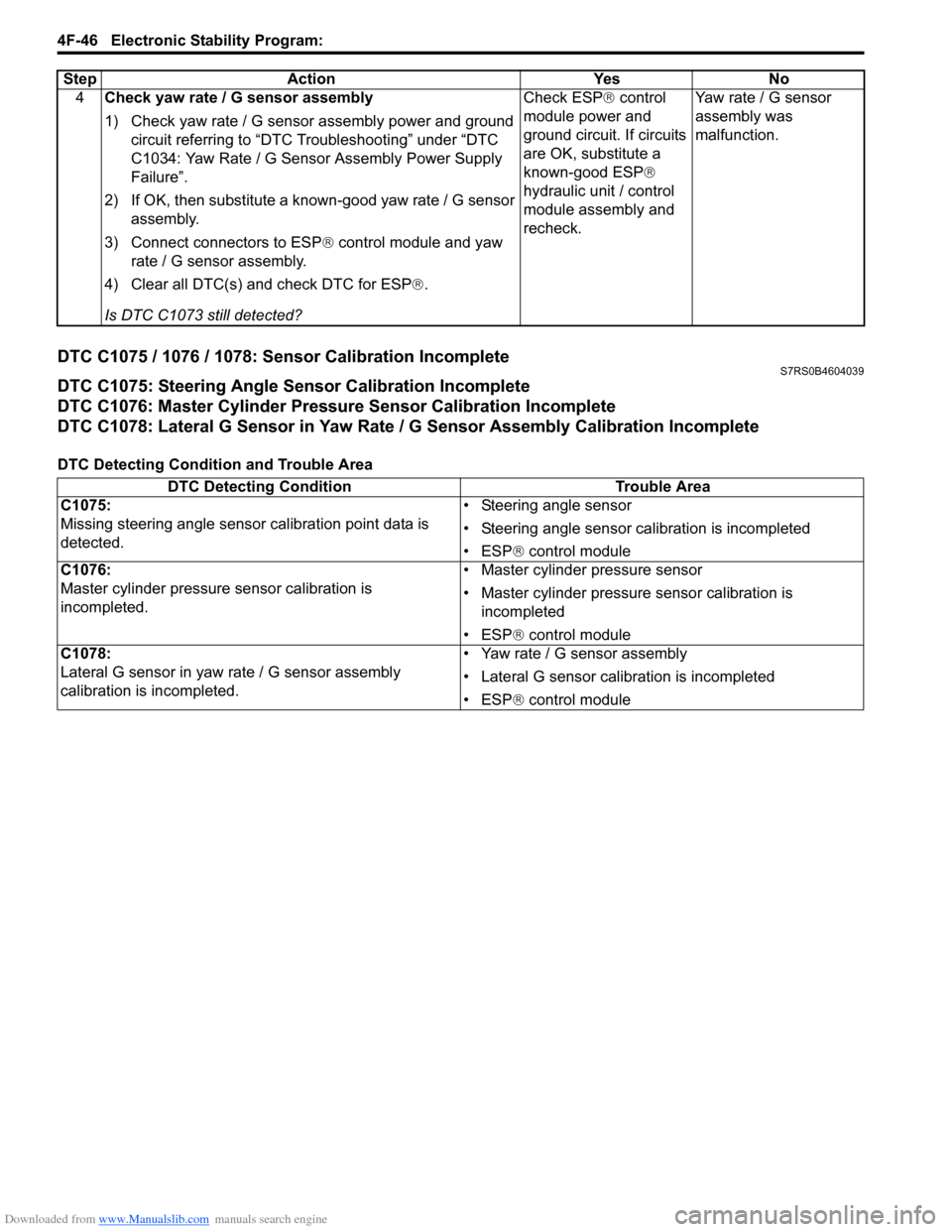
DTC C1075 / 1076 / 1078: Sensor Calibration IncompleteS7RS0B4604039
DTC C1075: Steering Angle Sensor Calibration Incomplete
DTC C1076: Master Cylinder Pressure Sensor Calibration Incomplete
DTC C1078: Lateral G Sensor in Yaw Rate / G Sensor Assembly Calibration Incomplete
DTC Detecting Condition and Trouble Area4
Check yaw rate / G sensor assembly
1) Check yaw rate / G sensor assembly power and ground
circuit referring to “DTC Troubleshooting” under “DTC
C1034: Yaw Rate / G Sensor Assembly Power Supply
Failure”.
2) If OK, then substitute a known-good yaw rate / G sensor assembly.
3) Connect connectors to ESP ® control module and yaw
rate / G sensor assembly.
4) Clear all DTC(s) and check DTC for ESP ®.
Is DTC C1073 still detected? Check ESP
® control
module power and
ground circuit. If circuits
are OK, substitute a
known-good ESP ®
hydraulic unit / control
module assembly and
recheck. Yaw rate / G sensor
assembly was
malfunction.
Step Action Yes No
DTC Detecting Condition
Trouble Area
C1075:
Missing steering angle sensor calibration point data is
detected. • Steering angle sensor
• Steering angle sensor ca
libration is incompleted
• ESP ® control module
C1076:
Master cylinder pressure sensor calibration is
incompleted. • Master cylinder pressure sensor
• Master cylinder pressure sensor calibration is
incompleted
• ESP ® control module
C1078:
Lateral G sensor in yaw ra te / G sensor assembly
calibration is incompleted. • Yaw rate / G sensor assembly
• Lateral G sensor calibration is incompleted
• ESP
® control module
Page 624 of 1496

Downloaded from www.Manualslib.com manuals search engine 4F-50 Electronic Stability Program:
DTC Troubleshooting
DTC U1100: Lost Communication with ECM (Reception Error)S7RS0B4604058
Wiring Diagram
Refer to “Wiring Diagram” under “DTC U1073: Control Module Communication Bus Off”.
DTC Detecting Condition and Trouble Area
DTC TroubleshootingStep Action Yes No
1 Was “Electronic Stability Pr ogram Check” performed? Go to Step 2. Go to “Electronic
Stability Program
System Check”.
2 DTC check for ESP®
1) Check connection of connectors of all control modules
communicating by means of CAN.
2) Recheck DTC for ESP ®.
Is DTC U1073 indicated? Go to Step 3. Intermittent trouble.
Check for intermittent
referring to “Intermittent
and Poor Connection
Inspection in Section
00”.
3 CAN communication circuit check
1) Turn ignition switch to OFF position.
2) Disconnect connectors of all control modules
communicating by means of CAN.
3) Check CAN communication circuit between control modules for open, short and high resistance.
Is each CAN communication circuit in good condition? Go to Step 4. Repair or replace the
CAN communication
line.
4 DTC check for ESP®
1) Connect connectors of disconnected control modules
communicating by means of CAN.
2) Disconnect each connector. •ECM
• Keyless start control module (if equipped)
• Combination meter
• Steering angle sensor
•BCM
3) Recheck DTC for ESP ®.
Is DTC U1073 detected? Check ESP
® control
module power and
ground circuit. If circuits
are OK, substitute a
known-good ESP ®
hydraulic unit / control
module assembly and
recheck. Check applicable
control module power
and ground circuit. If
circuit is OK, substitute
a known-good
applicable control
module and recheck.
DTC Detecting Condition
Trouble Area
ECM message data is missing from CAN communication. • CAN communication circuit
•ECM
• ESP® control module
Step Action YesNo
1 Was “Electronic Stability Pr ogram Check” performed? Go to Step 2.Go to “Electronic
Stability Program
System Check”.
2 DTC check for ESP®
1) Check DTC for ESP ®.
Is DTC U1100 and DTC U1073 detected together? Go to “DTC U1073:
Control Module
Communication Bus
Off”.Go to Step 3.
3 DTC check for ECM
1) Check DTC for ECM.
Is DTC P1674 detected? Go to “DTC P1674:
CAN Communication
(Bus Off Error) in
Section 1A”.Go to Step 4.
Page 625 of 1496

Downloaded from www.Manualslib.com manuals search engine Electronic Stability Program: 4F-51
DTC U1126: Lost Communication with Steering Angle Sensor (Reception Error)S7RS0B4604043
Wiring Diagram
Refer to “Wiring Diagram” under “DTC U1073: Control Module Communication Bus Off”.
DTC Detecting Condition and Trouble Area
DTC Troubleshooting4
Check each control module connectors
1) Check connection of connectors of all control modules
communicating by means of CAN.
2) Check DTC for ESP ®.
Is DTC U1100 detected? Go to Step 5. Check for intermittent
trouble referring to
“Intermittent and Poor
Connection Inspection
in Section 00”.
5 CAN communication circuit check
1) Turn ignition switch to OFF position.
2) Disconnect connectors of ESP ® control module and
ECM communicating by means of CAN.
3) Check CAN communication circuit between ESP®
control module and ECM for open, short and high
resistance.
Is each CAN communication circuit in good condition? Repair or replace the
CAN communication
line.
Go to Step 6.
6 CAN communication circuit check
1) Disconnect connectors of all control modules
communicating by means of CAN.
2) Check CAN communication circuit between control modules other than Step 5 for open, short and high
resistance.
Is each CAN communication circuit in good condition? Go to Step 7. Repair or replace the
CAN communication
line.
7 DTC check for ESP®
1) Connect connectors of disconnected control modules
communicating by means of CAN.
2) Disconnect each connector. •ECM
• Keyless start control module (if equipped)
• Combination meter
• Steering angle sensor
•BCM
3) Recheck DTC for ESP ®.
Is DTC U1100 detected? Check ESP
® control
module power and
ground circuit. If circuits
are OK, substitute a
known-good ESP ®
hydraulic unit / control
module assembly and
recheck. Check applicable
control module power
and ground circuit. If
circuit is OK, substitute
a known-good
applicable control
module and recheck.
Step Action Yes No
DTC Detecting Condition
Trouble Area
Steering angle sensor message data is missing from CAN
communication. • CAN communication circuit
• Steering angle sensor
• ESP
® control module
Step Action YesNo
1 Was “Electronic Stability Pr ogram Check” performed? Go to Step 2.Go to “Electronic
Stability Program
System Check”.
2 DTC check for ESP®
1) Check DTC for ESP ®.
Is DTC U1126 and DTC U1073 detected together? Go to “DTC U1073:
Control Module
Communication Bus
Off”.Go to Step 3.
Page 626 of 1496

Downloaded from www.Manualslib.com manuals search engine 4F-52 Electronic Stability Program:
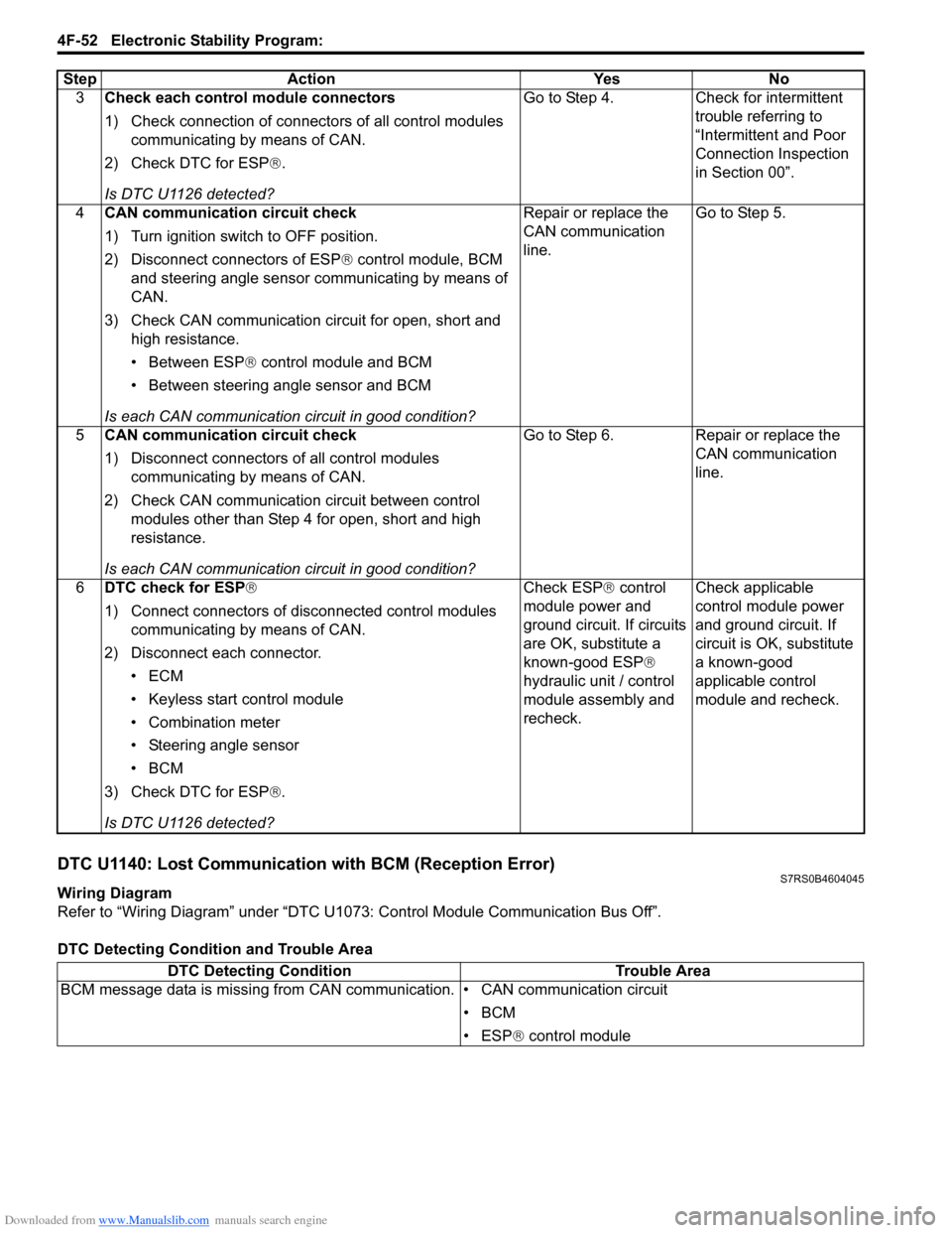
DTC U1140: Lost Communication with BCM (Reception Error)S7RS0B4604045
Wiring Diagram
Refer to “Wiring Diagram” under “DTC U1073: Control Module Communication Bus Off”.
DTC Detecting Condition and Trouble Area3
Check each control module connectors
1) Check connection of connectors of all control modules
communicating by means of CAN.
2) Check DTC for ESP ®.
Is DTC U1126 detected? Go to Step 4. Check for intermittent
trouble referring to
“Intermittent and Poor
Connection Inspection
in Section 00”.
4 CAN communication circuit check
1) Turn ignition switch to OFF position.
2) Disconnect connectors of ESP ® control module, BCM
and steering angle sensor communicating by means of
CAN.
3) Check CAN communication circuit for open, short and high resistance.
• Between ESP ® control module and BCM
• Between steering angle sensor and BCM
Is each CAN communication circuit in good condition? Repair or replace the
CAN communication
line.
Go to Step 5.
5 CAN communication circuit check
1) Disconnect connectors of all control modules
communicating by means of CAN.
2) Check CAN communication circuit between control modules other than Step 4 for open, short and high
resistance.
Is each CAN communication circuit in good condition? Go to Step 6. Repair or replace the
CAN communication
line.
6 DTC check for ESP®
1) Connect connectors of disconnected control modules
communicating by means of CAN.
2) Disconnect each connector. •ECM
• Keyless start control module
• Combination meter
• Steering angle sensor
•BCM
3) Check DTC for ESP ®.
Is DTC U1126 detected? Check ESP
® control
module power and
ground circuit. If circuits
are OK, substitute a
known-good ESP ®
hydraulic unit / control
module assembly and
recheck. Check applicable
control module power
and ground circuit. If
circuit is OK, substitute
a known-good
applicable control
module and recheck.
Step Action Yes No
DTC Detecting Condition
Trouble Area
BCM message data is missing from CAN communication. • CAN communication circuit
•BCM
• ESP® control module
Page 627 of 1496

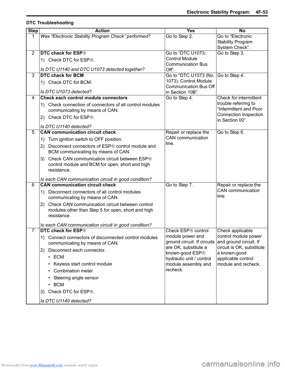
Downloaded from www.Manualslib.com manuals search engine Electronic Stability Program: 4F-53
DTC TroubleshootingStep Action Yes No 1 Was “Electronic Stability Pr ogram Check” performed? Go to Step 2. Go to “Electronic
Stability Program
System Check”.
2 DTC check for ESP®
1) Check DTC for ESP ®.
Is DTC U1140 and DTC U1073 detected together? Go to “DTC U1073:
Control Module
Communication Bus
Off”.Go to Step 3.
3 DTC check for BCM
1) Check DTC for BCM.
Is DTC U1073 detected? Go to “DTC U1073 (No.
1073): Control Module
Communication Bus Off
in Section 10B”.Go to Step 4.
4 Check each control module connectors
1) Check connection of connectors of all control modules
communicating by means of CAN.
2) Check DTC for ESP ®.
Is DTC U1140 detected? Go to Step 4. Check for intermittent
trouble referring to
“Intermittent and Poor
Connection Inspection
in Section 00”.
5 CAN communication circuit check
1) Turn ignition switch to OFF position.
2) Disconnect connectors of ESP ® control module and
BCM communicating by means of CAN.
3) Check CAN communication circuit between ESP®
control module and BCM for open, short and high
resistance.
Is each CAN communication circuit in good condition? Repair or replace the
CAN communication
line.
Go to Step 6.
6 CAN communication circuit check
1) Disconnect connectors of all control modules
communicating by means of CAN.
2) Check CAN communication circuit between control modules other than Step 5 for open, short and high
resistance.
Is each CAN communication circuit in good condition? Go to Step 7. Repair or replace the
CAN communication
line.
7 DTC check for ESP®
1) Connect connectors of disconnected control modules
communicating by means of CAN.
2) Disconnect each connector. •ECM
• Keyless start control module
• Combination meter
• Steering angle sensor
•BCM
3) Check DTC for ESP ®.
Is DTC U1140 detected? Check ESP
® control
module power and
ground circuit. If circuits
are OK, substitute a
known-good ESP ®
hydraulic unit / control
module assembly and
recheck. Check applicable
control module power
and ground circuit. If
circuit is OK, substitute
a known-good
applicable control
module and recheck.
Page 629 of 1496

Downloaded from www.Manualslib.com manuals search engine Electronic Stability Program: 4F-55
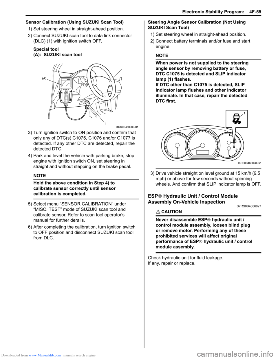
Sensor Calibration (Using SUZUKI Scan Tool)1) Set steering wheel in straight-ahead position.
2) Connect SUZUKI scan tool to data link connector (DLC) (1) with ignition switch OFF.
Special tool
(A): SUZUKI scan tool
3) Turn ignition switch to ON position and confirm that
only any of DTC(s) C1075, C1076 and/or C1077 is
detected. If any other DTC are detected, repair the
detected DTC.
4) Park and level the vehicle with parking brake, stop engine with ignition switch ON, set steering in
straight and without step ping on the brake pedal.
NOTE
Hold the above condition in Step 4) to
calibrate sensor correctly until sensor
calibration is completed.
5) Select menu “SENSOR CALIBRATION” under
“MISC. TEST” mode of SUZUKI scan tool and
calibrate sensor. Refer to scan tool operator's
manual for further derails.
6) After completing the calibra tion, turn ignition switch
to OFF position and disconnect SUZUKI scan tool
from DLC. Steering Angle Sensor Calibration (Not Using
SUZUKI Scan Tool)
1) Set steering wheel in straight-ahead position.
2) Connect battery terminals and/or fuse and start engine.
NOTE
When power is not supplied to the steering
angle sensor by removing battery or fuse,
DTC C1075 is detected and SLIP indicator
lamp (1) flashes.
If DTC other than C1075 is detected, SLIP
indicator lamp flushes and other indicator
illuminate. In that case, repair the detected
DTC first.
3) Drive vehicle straight on level ground at 15 km/h (9.5 mph) or above for few seconds without spinning
wheels. And confirm that SLIP indicator lamp is OFF.
ESP ® Hydraulic Unit / Control Module
Assembly On-Vehicle Inspection
S7RS0B4606027
CAUTION!
Never disassemble ESP ® hydraulic unit /
control module assembly, loosen blind plug
or remove motor. Pe rforming any of these
prohibited services will affect original
performance of ESP ® hydraulic unit / control
module assembly.
Check hydraulic unit for fluid leakage.
If any, repair or replace.
(A)
1
I4RS0B450003-01
1
I6RS0B460028-02
Page 867 of 1496

Downloaded from www.Manualslib.com manuals search engine Table of Contents 6- i
6
Section 6
CONTENTS
Steering
Precautions ................................................. 6-1
Precautions............................................................. 6-1
Precautions on Steering........................................ 6-1
Steering General Diagnosi s.................... 6A-1
Precautions........................................................... 6A-1
Precautions for Steering Diagnosis ..................... 6A-1
Diagnostic Information and Procedures ............ 6A-2 Steering Symptom Diagnosis .............................. 6A-2
Steering Wheel and Column ................... 6B-1
Precautions........................................................... 6B-1
Service Precautions of Steering Wheel and Column.............................................................. 6B-1
General Description ............................................. 6B-1 Steering Wheel and Column Construction .......... 6B-1
Diagnostic Information and Procedures ............ 6B-2 Checking Steering Column for Accident Damage ............................................................ 6B-2
Repair Instructions .............................................. 6B-3 Steering Wheel and Column Construction .......... 6B-3
Steering Wheel Removal and Installation ........... 6B-4
Contact Coil Cable Assembly Removal and Installation ......................................................... 6B-5
Centering Contact Coil Cable Assembly ............. 6B-6
Contact Coil Cable Assembly Inspection ............ 6B-6
Steering Angle Sensor Removal and Installation ......................................................... 6B-6
Steering Angle Sensor Inspection ....................... 6B-6
Steering Column Removal and Installation ......... 6B-7
Steering Column Inspecti on ................................ 6B-8
Ignition Switch Cylinder Assembly Removal and Installation (Non- Keyless Start Model)...... 6B-9
Steering Lock Assembly (Ignition Switch) Removal and Installation................................... 6B-9
Steering Lower Shaft Removal and Installation ....................................................... 6B-10
Specifications ..................................................... 6B-11
Tightening Torque Specifications ...................... 6B-11
Special Tools and Equipmen t ........................... 6B-11
Special Tool ...................................................... 6B-11
Power Assisted Steering System........... 6C-1
Precautions........................................................... 6C-1 Steering System Note .........................................6C-1
Precautions in Diagnosing Troubles ...................6C-1
General Description .............................................6C-2 P/S System Description ......................................6C-2
EPS Diagnosis General Descr iption ...................6C-3
On-Board Diagnostic System Description ...........6C-3
Schematic and Routing Diagram ........................6C-4 EPS System Wiring Circuit Diagram ...................6C-4
Diagnostic Information and Procedures ............6C-5 EPS System Check .............. ...............................6C-5
“EPS” Warning Light Check . ...............................6C-8
DTC Check..........................................................6C-8
DTC Clearance ...................................................6C-9
DTC Table ...........................................................6C-9
Scan Tool Data .................................................6C-11
Visual Inspection ...............................................6C-12
P/S System Symptom Diagnosis ......................6C-12
Serial Data Link Circuit Check ..........................6C-13
“EPS” Warning Light Do es Not Come ON with
Ignition Switch Turn ed ON before Engine
Starts ...............................................................6C-15
“EPS” Warning Light Remains ON Steady after Engine Starts ..........................................6C-16
DTC C1113: Steering Torque Sensor (Main and Sub) Circuit Correlation ............................6C-17
DTC C1114: Steering Torque Sensor Reference Power Supply Circuit .....................6C-19
DTC C1117: Steering Torque Sensor Failure Signal Circuit Low ...........................................6C-21
DTC C1118: Steering Torque Sensor Failure Signal Circuit High...........................................6C-22
DTC C1119: Steering Torque Sensor Power Supply Circuit ..................................................6C-24
DTC C1121 / C1123 / C1124: VSS Circuit
Failure .............................................................6C-26
DTC C1122: Engine Speed Signal....................6C-28
DTC C1141 / C1142 / C1143 / C1145: P/S Motor Circuit Failure ........................................6C-30
DTC C1153: P/S Control Module Power Supply Circuit Voltage Low .............................6C-32
DTC C1155: P/S Control Module Failure ..........6C-33
P/S Control Module Power Supply and Ground Circuit Check ......................................6C-34
Inspection of P/S Control Module and Its Circuits ............................................................6C-35
Page 883 of 1496

Downloaded from www.Manualslib.com manuals search engine Power Assisted Steering System: 6C-1
Steeri ng
Power Assisted Steering System
Precautions
Steering System NoteS7RS0B6300001
NOTE
All steering gear fasteners are important attaching parts in that they could affect the performance of
vital parts and systems, and/or could result in major repair expense. They must be replaced with one of
the same part number or with an equivalent part if replacement becomes necessary. Do not use a
replacement part of lesser quality or substitute design. Torque values must be used as specified
during reassembly to assure proper retention of these parts.
Precautions in Diagnosing TroublesS7RS0B6300002
• Take a note of DTC indicated on the SUZUKI scan tool.
• Before inspection, be sure to read “Pre cautions for Electrical Circuit Service in Section 00” and understand what is
written there.
• DTC C1122 (engine speed signal failure) is indicated when ignition switch is at ON position and engine is not
running, but it means there is nothing abnormal if indica tion changes to a normal one when engine is started.
• As DTC is stored in memory of the P/S control module, be sure to clear memory after repair by performing the
procedure described in “DTC Clearance”.