2006 SUZUKI SWIFT brake pad
[x] Cancel search: brake padPage 528 of 1496

Downloaded from www.Manualslib.com manuals search engine 4C-4 Rear Brakes:
5) Remove caliper pin bolts (1).
6) Remove caliper (2) from brake caliper carrier (3).
7) Disconnect parking brake cable (1) from lever (2) while rotating lever in direction of arrow.
8) Remove brake pads, slide pins and slide pin boots from brake caliper carrier.
9) Remove brake caliper carrier (1) from spindle (2). Installation
1) Install brake caliper ca rrier (1) to spindle (2).
Tightening torque
Brake caliper carrier bolt (a): 60 N·m (6.0 kgf-m,
43.5 lb-ft)
2) Install new slide pin boots (1) to brake caliper carrier.
3) Apply rubber grease to slide pins, then install slide pin to front side and slide pin to rear side of brake
caliper carrier.
NOTE
Be sure not to install wrongly because the
shape of slide pins are different as below.
1 3
2
I6RS0C430008-01
1
2
I6RS0B431011-01
1 2
I6RS0B431012-01
F: Vehicle front
1
2
(a)
I6RS0B431023-01
I6RS0C430009-02
Page 529 of 1496

Downloaded from www.Manualslib.com manuals search engine Rear Brakes: 4C-5
4) Pass parking brake cable (1) through bracket (3) of caliper.
5) Hang parking brake cable on lever (2) as follows.
NOTE
Make sure that lever (4) contacts pin (5).
6) Install brake pads and caliper referring to “Rear Disc Brake Pad Removal and Installation”.
7) Connect flexible hose (1) with new washers to caliper (2).
WARNING!
Make sure that flexible hose is not twisted
when tightening joint bolt. If it is twisted,
reconnect it using care not to twist it.
Tightening torque
Flexible hose joint bolt (a): 23 N·m (2.3 kgf-m,
17.0 lb-ft) 8) Install brake cable clip (1) securely to bracket (2).
9) After reassembling brake lines, bleed air from them
referring to “Air Bleeding of Brake System in Section
4A”.
10) Check to make sure that system is free from fluid
leakage.
11) Start engine and then depress brake pedal with about 300 N (30 kg, 66 lbs) load 3 times or more so
as to obtain proper disc to pad clearance.
12) Check to make sure that parking brake lever stroke is as specified. Refer to “Parking Brake Inspection
and Adjustment in Section 4D”.
13) Tighten wheel nuts to specified torque.
Tightening torque
Wheel bolt: 85 N·m (8.5 kgf-m, 61.5 lb-ft)
14) Remove vehicle from hoist and perform brake test (foot brake and parking brake).
1
23
45
I6RS0C430010-01
1 (a)2
I6RS0C430011-01
1
2
I6RS0C430012-01
Page 530 of 1496

Downloaded from www.Manualslib.com manuals search engine 4C-6 Rear Brakes:
Rear Disc Brake Pad InspectionS7RS0B4306004
Check pad lining for wear. When wear exceeds limit,
replace with new one.
CAUTION!
Never polish pad lining with sandpaper. If
lining is polished with sandpaper, hard
particles of sandpaper will be deposited in
lining and may damage disc. When pad lining
requires correction, replace it with a new one.
Rear brake pad thickness (lining thickness)
Standard: 9.0 mm (0.354 in.)
Limit: 1.0 mm (0.039 in.)
NOTE
When pads are removed, visually inspect
caliper for brake fluid leak. Correct leaky
point, if any.
Rear Disc Brake Caliper Disassembly and
Assembly
S7RS0B4306005
Disassembly
CAUTION!
Clean around caliper with brake fluid before
disassembly.
1) Remove disc brake piston (1) by turning piston counterclockwise with special tool.
CAUTION!
Be careful not to damage inside (bore side) of
cylinder.
Special tool
(A): 09945–16060 2) Remove cylinder boot and piston seal (1).
CAUTION!
Be careful not to damage inside (bore side) of
cylinder.
3) Remove bleeder plug and cap from caliper.
4) Remove return spring (1), parking nut (2), washer
(3), lever (4) and shaft cover (5).
I6RS0B431034-01
(A)
1
I6RS0B431013-01
1
I6RS0B431014-01
1
2
3
4
5
I6RS0B431015-01
Page 531 of 1496

Downloaded from www.Manualslib.com manuals search engine Rear Brakes: 4C-7
Assembly
CAUTION!
• Wash each part cleanly before installation in the same fluid as the one used in master
cylinder reservoir.
• Never use other fluid or thinner.
• Before installing caliper to brake caliper carrier, install slide pins with grease
applied into carrier hole and check for its
smooth movement in thrust direction.
• Before installing piston seal to cylinder, apply fluid to them.
• Install a piston seal into groove in cylinder securely making sure that it is not twisted.
1) Apply thread lock cement to shaft thread (6) of caliper.
“A”: Thread lock cement 99000–32110 (Thread
Lock Cement Super 1322)
2) Apply grease to inside of new shaft cover (1).
3) Install new shaft cover, leve r (2), washer (3), parking
nut (4) and return spring (5) to caliper.
Tightening torque
Parking nut (a): 27 N·m (2.7 kgf-m, 19.5 lb-ft) 4) Install bleeder plug and cap to caliper.
5) Install new piston seal to caliper.
6) Before inserting piston (2) into cylinder, install boot
(1) onto piston as shown.
7) Fit boot as it is in figure into boot groove in cylinder with fingers.
8) Turn brake caliper piston clockwise to obtain clearance between brake disc and pads.
NOTE
Check that boot is fitted in boot groove
securely all around piston.
Special tool
(A): 09945–16060
5
4, (a)
2
3
1
6, “A”
I6RS0C430016-01
[A]: Cylinder side
[B]: Brake pad side
[A] [B]
I6RS0B431017-01
I6RS0B431033-01
I6RS0B431018-01
Page 533 of 1496

Downloaded from www.Manualslib.com manuals search engine Rear Brakes: 4C-9
Rear Brake Disc Removal and InstallationS7RS0B4306008
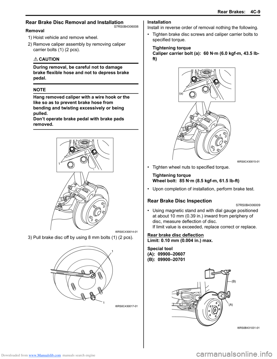
Removal1) Hoist vehicle and remove wheel.
2) Remove caliper assembly by removing caliper
carrier bolts (1) (2 pcs).
CAUTION!
During removal, be ca reful not to damage
brake flexible hose and not to depress brake
pedal.
NOTE
Hang removed caliper with a wire hook or the
like so as to prevent brake hose from
bending and twisting excessively or being
pulled.
Don’t operate brake pedal with brake pads
removed.
3) Pull brake disc off by using 8 mm bolts (1) (2 pcs). Installation
Install in reverse order of removal nothing the following.
• Tighten brake disc screws and caliper carrier bolts to
specified torque.
Tightening torque
Caliper carrier bolt (a): 60 N·m (6.0 kgf-m, 43.5 lb-
ft)
• Tighten wheel nuts to specified torque. Tightening torque
Wheel bolt: 85 N·m (8.5 kgf-m, 61.5 lb-ft)
• Upon completion of installation, perform brake test.
Rear Brake Disc InspectionS7RS0B4306009
• Using magnetic stand and with dial gauge positioned at about 10 mm (0.39 in.) inward from periphery of
disc, measure deflection of disc.
If limit value is exceeded, replace correct or replace.
Rear brake disc deflection
Limit: 0.10 mm (0.004 in.) max.
Special tool
(A): 09900–20607
(B): 09900–20701
1
I6RS0C430014-01
1 1I6RS0C430017-01
(a)
I6RS0C430015-01
(B)
(A)
I6RS0B431031-01
Page 580 of 1496

Downloaded from www.Manualslib.com manuals search engine 4F-6 Electronic Stability Program:
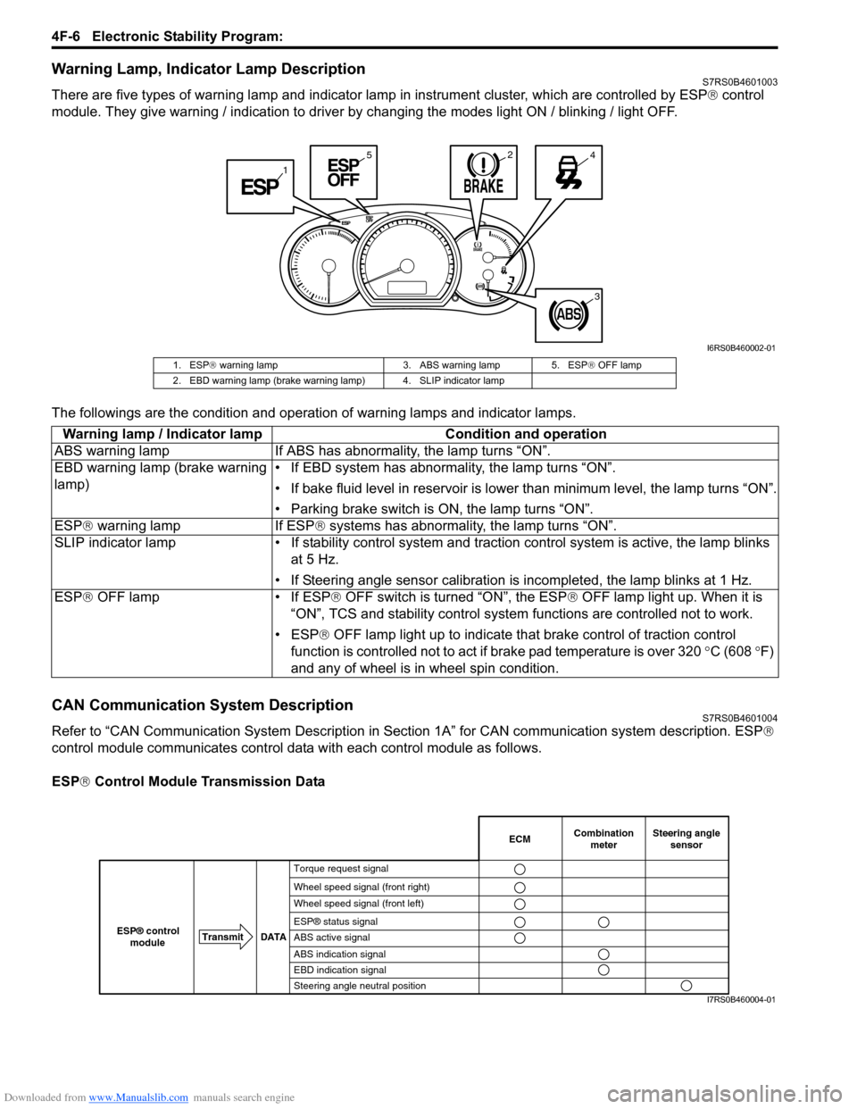
Warning Lamp, Indicator Lamp DescriptionS7RS0B4601003
There are five types of warning lamp and indicator lamp in instrument cluster, which are controlled by ESP ® control
module. They give warning / indication to driver by changing the modes light ON / blinking / light OFF.
The followings are the condition and operation of warning lamps and indicator lamps.
CAN Communication System DescriptionS7RS0B4601004
Refer to “CAN Communication System Description in Section 1A” for CAN communication system description. ESP ®
control module communicates control data with each control module as follows.
ESP ® Control Module Transmission Data
1
245
3
I6RS0B460002-01
1. ESP ® warning lamp 3. ABS warning lamp 5. ESP ® OFF lamp
2. EBD warning lamp (brake warning lamp) 4. SLIP indicator lamp
Warning lamp / Indicator lamp Condition and operation
ABS warning lamp If ABS has abnor mality, the lamp turns “ON”.
EBD warning lamp (brake warning
lamp) • If EBD system has abnormality, the lamp turns “ON”.
• If bake fluid level in reservoir is lower
than minimum level, the lamp turns “ON”.
• Parking brake switch is ON, the lamp turns “ON”.
ESP ® warning lamp If ESP ® systems has abnormality, the lamp turns “ON”.
SLIP indicator lamp • If stability cont rol system and traction control system is active, the lamp blinks
at 5 Hz.
• If Steering angle sensor calibration is incompleted, the lamp blinks at 1 Hz.
ESP ® OFF lamp • If ESP ® OFF switch is turned “ON”, the ESP ® OFF lamp light up. When it is
“ON”, TCS and stability control system functions are controlled not to work.
• ESP® OFF lamp light up to indicate th at brake control of traction control
function is controlled not to act if brake pad temperature is over 320 °C (608 °F)
and any of wheel is in wheel spin condition.
Combination
meter
Transmit DATA
ESP® control
moduleECMSteering angle sensor
Torque request signal
Wheel speed signal (front right)
Wheel speed signal (front left)
ESP® status signal
ABS active signal
ABS indication signal
EBD indication signal
Steering angle neutral position
I7RS0B460004-01
Page 609 of 1496

Downloaded from www.Manualslib.com manuals search engine Electronic Stability Program: 4F-35
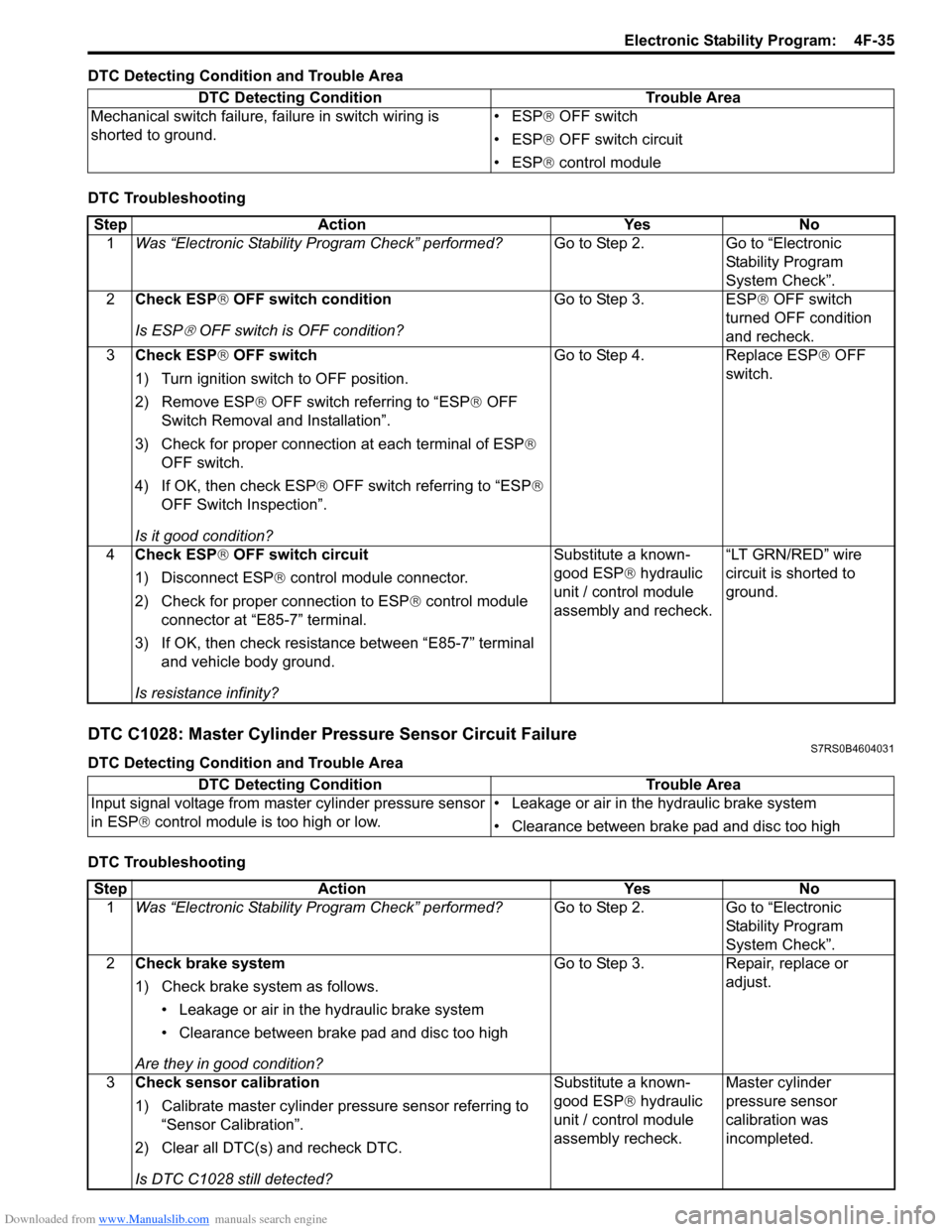
DTC Detecting Condition and Trouble Area
DTC Troubleshooting
DTC C1028: Master Cylinder Pressure Sensor Circuit FailureS7RS0B4604031
DTC Detecting Condition and Trouble Area
DTC TroubleshootingDTC Detecting Condition Trouble Area
Mechanical switch failure, fa ilure in switch wiring is
shorted to ground. • ESP
® OFF switch
• ESP ® OFF switch circuit
• ESP ® control module
Step Action YesNo
1 Was “Electronic Stability Pr ogram Check” performed? Go to Step 2.Go to “Electronic
Stability Program
System Check”.
2 Check ESP ® OFF switch condition
Is ESP
® OFF switch is OFF condition? Go to Step 3. ESP
® OFF switch
turned OFF condition
and recheck.
3 Check ESP ® OFF switch
1) Turn ignition switch to OFF position.
2) Remove ESP® OFF switch referring to “ESP ® OFF
Switch Removal and Installation”.
3) Check for proper connection at each terminal of ESP ®
OFF switch.
4) If OK, then check ESP ® OFF switch referring to “ESP ®
OFF Switch Inspection”.
Is it good condition? Go to Step 4. Replace ESP
® OFF
switch.
4 Check ESP ® OFF switch circuit
1) Disconnect ESP ® control module connector.
2) Check for proper connection to ESP ® control module
connector at “E85-7” terminal.
3) If OK, then check resistance between “E85-7” terminal and vehicle body ground.
Is resistance infinity? Substitute a known-
good ESP
® hydraulic
unit / control module
assembly and recheck. “LT GRN/RED” wire
circuit is shorted to
ground.
DTC Detecting Condition
Trouble Area
Input signal voltage from master cylinder pressure sensor
in ESP ® control module is too high or low. • Leakage or air in the hydraulic brake system
• Clearance between brake pad and disc too high
Step
Action YesNo
1 Was “Electronic Stability Pr ogram Check” performed? Go to Step 2.Go to “Electronic
Stability Program
System Check”.
2 Check brake system
1) Check brake system as follows.
• Leakage or air in the hydraulic brake system
• Clearance between brake pad and disc too high
Are they in good condition? Go to Step 3.
Repair, replace or
adjust.
3 Check sensor calibration
1) Calibrate master cylinder pressure sensor referring to
“Sensor Calibration”.
2) Clear all DTC(s) and recheck DTC.
Is DTC C1028 still detected? Substitute a known-
good ESP
® hydraulic
unit / control module
assembly recheck. Master cylinder
pressure sensor
calibration was
incompleted.
Page 859 of 1496

Downloaded from www.Manualslib.com manuals search engine Clutch: 5C-7
Clutch Operating Cylinder Removal and
Installation
S7RS0B5306010
Removal1) Clean around brake master cylinder reservoir cap and take out fluid with syringe or such from brake
master cylinder reservoir.
2) Disconnect clutch fluid pipe (2) from operating cylinder referring to “Clutch Fluid Pipe Removal and
Installation”.
3) Remove clutch operating cylinder (1).
Installation
Reverse removal procedure for installation noting the
following. • Apply grease to push rod tip.
“A”: Grease 99000–25100 (SUZUKI Silicone
Grease)
• Tighten clutch operating cylinder bolt to specified torque.
Tightening torque
Clutch operating cylinder bolt: 23 N·m (2.3 kgf-
m, 17.0 lb-ft)
Clutch Operating Cylinder InspectionS7RS0B5306011
Check operating cylinder for damage and fluid leakage.
If malfunction is found, repl ace clutch operating cylinder.
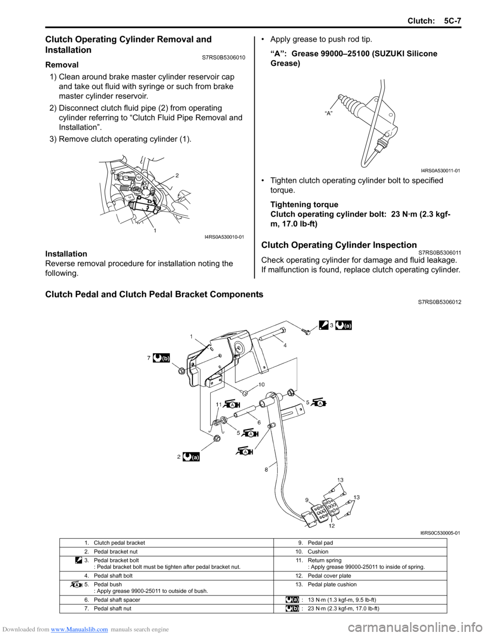
Clutch Pedal and Clutch Pedal Bracket ComponentsS7RS0B5306012
2
1I4RS0A530010-01
“A”
I4RS0A530011-01
I6RS0C530005-01
1. Clutch pedal bracket 9. Pedal pad
2. Pedal bracket nut 10. Cushion
3. Pedal bracket bolt : Pedal bracket bolt must be tighten after pedal bracket nut. 11. Return spring
: Apply grease 99000-25011 to inside of spring.
4. Pedal shaft bolt 12. Pedal cover plate
5. Pedal bush : Apply grease 9900-25011 to outside of bush. 13. Pedal plate cushion
6. Pedal shaft spacer : 13 N⋅m (1.3 kgf-m, 9.5 lb-ft)
7. Pedal shaft nut : 23 N⋅m (2.3 kgf-m, 17.0 lb-ft)