2006 SUZUKI SWIFT battery description
[x] Cancel search: battery descriptionPage 416 of 1496

Downloaded from www.Manualslib.com manuals search engine 1J-6 Charging System:
Generator Test (Overcharged Battery Check)S7RS0B1A04004
1) To determine battery condition, refer to “Battery Description”.
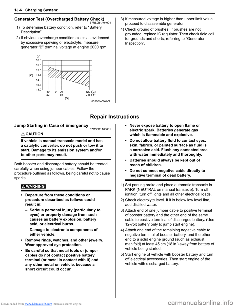
2) If obvious overcharge condition exists as evidenced by excessive spewing of electrolyte, measure
generator “B” terminal voltage at engine 2000 rpm. 3) If measured voltage is higher than upper limit value,
proceed to disassemble generator.
4) Check ground of brushes. If brushes are not grounded, replace IC regulator. Then check field coil
for grounds and shorts, referring to “Generator
Inspection”.
Repair Instructions
Jump Starting in Case of EmergencyS7RS0B1A06001
CAUTION!
If vehicle is manual transaxle model and has
a catalytic converter, do not push or tow it to
start. Damage to its emission system and/or
to other parts may result.
Both booster and discharged battery should be treated
carefully when using ju mper cables. Follow the
procedure outlined as follows, being careful not to cause
sparks.
WARNING!
• Departure from these conditions or procedure described as follows could
result in:
– Serious personal injury (particularly to eyes) or property damage from such
causes as battery explosion, battery
acid, or electrical burns.
– Damage to electronic components of either vehicle.
• Remove rings, watches, and other jewelry. Wear approved eye protection.
• Be careful so that metal tools or jumper cables do not contact positive battery
terminal (or metal in contact with it) and
any other metal on vehicle, because a
short circuit could occur. • Never expose battery to open flame or
electric spark. Batteries generate gas
which is flammable and explosive.
• Do not allow battery fluid to contact eyes, skin, fabrics, or painted surface as fluid is
a corrosive acid. Flush any contacted area
with water immediately and thoroughly.
• Batteries should always be kept out of reach of children.
• Do not connect negative cable directly to negative terminal of dead battery.
1) Set parking brake and place automatic transaxle in PARK (NEUTRAL on manual transaxle). Turn off
ignition, turn off lights and all other electrical loads.
2) Check electrolyte level. If it is below low level line, add distilled water.
3) Attach end of one jumper cable to positive terminal of booster battery and the other end of the same
cable to positive terminal of discharged battery. (Use
12-volt battery only to jump start engine).
4) Attach one end of the remaining negative cable to negative terminal of booster battery, and the other
end to a solid engine ground (such as exhaust
manifold) at least 45 cm (18 in.) away from battery of
vehicle being started.
5) Start engine of vehicle with booster battery and turn off electrical accessories. Then start engine of the
vehicle with discharged battery.
16.0
15.5
15.0
14.5
14.0
13.5
13.0 -30 0 20
[C]
[D]
68
22120 (˚C)
248 (˚F)
(V)
I6RS0C1A0001-02
Page 552 of 1496

Downloaded from www.Manualslib.com manuals search engine 4E-13 ABS:
ABS Warning Light Does Not Come ON at Ignition Switch ONS7RS0B4504008
Wiring Diagram
Circuit Description
Operation (ON/OFF) of ABS warning light is controlled by ABS contro l module through lamp driver module in
combination meter.
If the antilock brake system is in good condition, ABS control module turns ABS warning light ON at the ignition switch
ON, keeps it ON for 2 seconds and then turns it OFF. If an abnormality in the system is detected, ABS warning light is
turned ON continuously by ABS control module. Also, it is turned ON continuously by la mp driver module when the
connector of ABS control module is disconnected.
Troubleshooting
WHT/BLU
BLK 12V
9
BLK
E03-14
E03-13
E03-26
WHT/RED
GRN/ORNE03-7WHT/BLUGRN
1
2
3
48
RED/BLK
76
5
10
E03-112V[A]
E03
15
16
17
18
19
20
21
22
23
24
25 2
3
4
5
6
7
8
9
10
11
12
1
13
14
26
BLK/ORN
E03-12
E03-6
REDWHT
10
G28-8
G28-10
REDWHTE46-1
E46-2
RED/BLK
RED/BLK
RED
RED
WHT
WHT
12
13
11
10
G37-2
G37-4
I6RS0C450007-01
[A]: ABS hydraulic unit / control module connector (viewed from terminal side) 5. Combination meter 10. CAN driver
1. Battery 6. ABS warning light 11. BCM
2. Main fuse box 7. EBD warning light (Brake warning light) 12. Brake fluid level switch
3. Ignition switch 8. Lamp driver module 13. Parking brake switch
4. Circuit fuse box 9. ABS hydraulic unit / control module assembly
Step Action YesNo
1 1) Turn ignition switch to ON position.
Do other warning lights come ON? Go to Step 2.
Go to Step 3.
2 1) Connect scan tool to DLC with ignition switch turned OFF.
2) Turn ignition switch to ON position and check DTC.
Is there DTC U1073? Go to “DTC U1073:
Control Module
Communication Bus
Off”.
Substitute a known-
good combination meter
and recheck. If ABS
warning light remains
OFF, substitute a
known-good ABS
hydraulic unit / control
module assembly and
recheck.
3 Is Circuit fuse fo r combination meter in good condition? Go to Step 4.Replace fuse and check
for short circuit to
ground.
Page 576 of 1496

Downloaded from www.Manualslib.com manuals search engine 4F-2 Electronic Stability Program:
Perform sensor calibration according to “Sensor Calibration”.
Precautions in Speedometer Test or Other TestsS7RS0B4600005
When performing speedometer or other tests using speedometer tester or chassis dynamometer, ESP® function must
be deactivated by ESP ® OFF switch or using SUZUKI scan to ol to complete the tests correctly.
When using SUZUKI scan tool, set to the “MISC. TEST” mode to stop the ESP ® function. Refer to SUZUKI scan tool
operator's manual for further details.
General Description
Electronic Stability Program DescriptionS7RS0B4601006
Electronic Stability Program (ESP ®) is an auxiliary function to enable the vehicle to av oid a danger safely while the
vehicle is running, stopping or turning.
Electronic Stability Program (ESP ®) consists of following functions.
ESP ® is a registered trademark of Daimler Chrysler AG.
Antilock Brake System (ABS)
This system prevents tire locking which may occur when br ake is applied suddenly or on slippery roads. With this
function, as the vehicle body is kept in the stable state an d tires unlocked, the driver can avoid any obstacle by turning
the steering wheel.
Electronic Brake force Distribution (EBD)
This function distributes braking force of front and rear wheels properly according to the vehicle load condition.
With this function, the braking force of the front and rear wheels is controlled for the optimum effect to secure the
maximum braking force regardless of the loadage.
Traction Control System (TCS)
This system controls the engine and brake to prevent the dr iving wheels from spinning at the time of starting and
accelerating. Particularly, this fu nction is helpful for safe driving on muddy or icy roads. When ESP ® control module
detects wheel spinning using information from the yaw rate sensor and wheel speed sensor, it lower the engine torque
by closing the electronic controlled thro ttle and controlling ignition. At the same time, brake is applied to the spinning
tire.
Stability Control
This function controls the vehicle body in the stable state by controlling the engine and braking so as to prevent the
vehicle from over-steering or under-steering while turning.
When under-steering occurs, this function lowers the engine torque and applies brake to the inner rear wheel in the
vehicle forward direction so as to pr event the vehicle from moving outward.
When over-steering occurs, this function applies brake to the outer front wheel in the vehicle forward direction so as to
prevent the vehicle from moving inward. Sensor Procedures required calibration
Steering angle sensor • Power is not su pplied to steering angle sensor. (battery, fuse and/or connector is
removed.)
• Steering angle sensor is replaced.
• Power is not supplied to ESP ® control module. (battery, fuse and/or connector is
removed.)
• ESP® hydraulic unit / control module assembly is replaced.
Master cylinder pressure sensor • ESP® hydraulic unit / control module assembly is removed or replaced.
Yaw rate / G sensor assembly • Yaw rate / G sensor assembly is removed or replaced.
• ESP® hydraulic unit / control module assembly is replaced.
Page 595 of 1496

Downloaded from www.Manualslib.com manuals search engine Electronic Stability Program: 4F-21
Stability control (ACTIVE, INACTIVE): This indicates
stability control in acti vation / deactivation.
TCS control (brake) ( ACTIVE, INACTIVE): This
indicates brake function of TCS in activation /
deactivation.
TCS control (engine) (ACTIVE, INACTIVE): This
indicates torque control of TCS in activation /
deactivation. ESP®
off state (cont) (ESP ® ON, ESP ® OFF): State
of ESP ® OFF switch.
Steering angle Sen (Neutral, NON newtral): This
indicates steering wheel angle measured by steering
angle sensor is in straight-ahead or not.
Visual InspectionS7RS0B4604059
Check the following parts and systems visually.
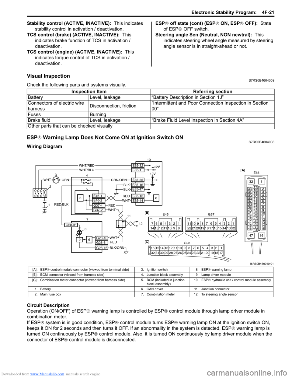
ESP ® Warning Lamp Does Not Come ON at Ignition Switch ONS7RS0B4604008
Wiring Diagram
Circuit Description
Operation (ON/OFF) of ESP ® warning lamp is controlled by ESP ® control module through lamp driver module in
combination meter.
If ESP ® system is in good condition, ESP ® control module turns ESP ® warning lamp ON at the ignition switch ON,
keeps it ON for 2 seconds and then turns it OFF. If an abnormality in the system is detected, ESP ® warning lamp is
turned ON continuously by ESP ® control module. Also, it is turned ON continuously by lamp driver module when the
connector of ESP ® control module is disconnected.Inspection Item Referring section
Battery Level, leakage “Battery Description in Section 1J”
Connectors of electric wire
harness Disconnection, friction“Intermittent and Poor Connec
tion Inspection in Section
00”
Fuses Burning
Brake fluid Level, leakage “Brake Fluid Level Inspection in Section 4A”
Other parts that can be checked visually
[A] E85
161
15
2
3
4
5
6
7
8
9
10
11
12
13
14
17
18
19
20
21
22
23
24
25
26
27
28
29
30
31
3233
34
35
36
37
38
39
40
41
42
43
44
45
46
47
WHTGRN
3
E85-13
E85-44REDWHT6 5E46-1E46-2
4 10
6
E85-16
E85-47BLKBLK
8
9
BLK/ORN
REDWHT
REDWHT
G37-4G37-2
G28-10G28-8
G28-16
12V
12VE85-32E85-1
E85-35
WHT/REDWHT/BLU
GRN/ORN
6
2
1
7 1112[B]
G37
E46124
53
67
891011121314124
53
67
891011
1213141516171819202122
[C] G28
12345678910111213141516
17181920212223242526272829303132
G28-31
RED/BLK
I6RS0B460010-01
[A]: ESP ® control module connector (viewed from terminal side) 3. Ignition switch 8. ESP ® warning lamp
[B]: BCM connector (viewed from harness side) 4. Junction block assembly 9. Lamp driver module
[C]: Combination meter connector (viewed from harness side) 5. BCM (included in junction
block assembly) 10. ESP
® hydraulic unit / control module assembly
1. Battery 6. CAN driver 11. Junction connector
2. Main fuse box 7. Combination meter 12. To steering angle sensor
Page 598 of 1496

Downloaded from www.Manualslib.com manuals search engine 4F-24 Electronic Stability Program:
Circuit Description
Operation (ON/OFF) of ABS warning lamp is controlled by ESP® control module through lamp driver module in
combination meter.
If antilock brake system is in good condition, ESP ® control module turns ABS warning lamp ON at the ignition switch
ON, keeps it ON for 2 seconds and then turns it OFF. If an abnormality in the system is detected, ABS warning lamp is
turned ON continuously by ESP ® control module. Also, it is turned ON continuously by lamp driver module when the
connector of ESP ® control module is disconnected.
Troubleshooting
Refer to “Troubleshooting” under “ESP ® Warning Lamp Does Not Come ON at Ignition Switch ON”.
ABS Warning Lamp Comes ON SteadyS7RS0B4604049
Wiring Diagram
Refer to “Wiring Diagram” under “ABS Warning Lamp Does Not Come ON at Ignition Switch ON”.
Circuit Description
Refer to “Circuit Description” u nder “ABS Warning Lamp Does Not Co me ON at Ignition Switch ON”.
Troubleshooting
Refer to “Troubleshooting” under “ESP ® Warning Lamp Comes ON Steady”.
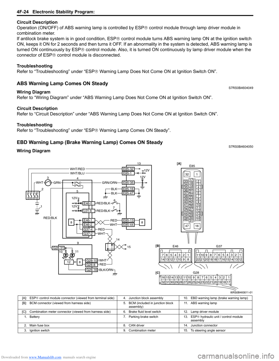
EBD Warning Lamp (Brake Warning Lamp) Comes ON SteadyS7RS0B4604050
Wiring Diagram
[A]
E85
161
15
2
3
4
5
6
7
8
9
10
11
12
13
14
17
18
19
20
21
22
23
24
25
26
27
28
29
30
31
3233
34
35
36
37
38
39
40
41
42
43
44
45
46
47WHTGRN
3
E85-13
E85-44REDWHT8 5E46-1E46-2
4
13
8
E85-16
E85-47BLKBLK
1110
12
BLK/ORN
REDWHT
REDWHT
G37-4G37-2
G28-10G28-8
G28-16
12V
12VE85-32E85-1
E85-35
WHT/REDWHT/BLU
GRN/ORN
8
2
1
9 1415
[B]
G37
E46
124
53
67
891011121314124
53
67
891011
1213141516171819202122
[C] G28
12345678910111213141516
17181920212223242526272829303132
12V
12V
6
7E46-5
L01-6
RED/BLK
RED/BLK
G28-31
RED/BLK
I6RS0B460011-01
[A]: ESP ® control module connector (viewed from terminal side) 4. Junction block assembly 10. EBD warning lamp (brake warning lamp)
[B]: BCM connector (viewed from harness side) 5. BCM (included in junction block
assembly) 11. ABS warning lamp
[C]: Combination meter connector (viewed from harness side) 6. Brake fluid level switch 12. Lamp driver module 1. Battery 7. Parking brake switch 13. ESP ® hydraulic unit / control module
assembly
2. Main fuse box 8. CAN driver 14. Junction connector
3. Ignition switch 9. Combination meter 15. To steering angle sensor
Page 884 of 1496

Downloaded from www.Manualslib.com manuals search engine 6C-2 Power Assisted Steering System:
General Description
P/S System DescriptionS7RS0B6301001
This power steering (P/S) system consists of a P/S control module (3), a torque sensor (4), a motor (5). In this system,
the P/S control module determines the level and direction of the assist force for the steering wheel (1) according to the
signals from the torque sensor and vehicle speed signal from ECM. The P/S control module runs the motor so as to
assist the operation of the steering wheel.
The P/S control module diagnoses troubles which may occur in the area including the following components when the
ignition switch is ON and the engine is running. When the P/S control module detects any malfunction, it stops the
motor operation.
• Torque sensor
• Vehicle speed signal
• Engine speed signal
• P/S motor
• P/S control module.
2. Steering column 7. Battery9. ABS/ESP® control module
6. Steering gear case assembly 8. ECM10. Wheel speed sensor (right-front, left-front)
7
3
9
10
10
1
2
4
5
6
8
I7RS0B630001-01
Page 894 of 1496

Downloaded from www.Manualslib.com manuals search engine 6C-12 Power Assisted Steering System:
Scan Tool Data Definitions
Battery Voltage
This parameter indicates battery positive voltage.
TQS Power Supply (Torque Sensor Power Supply, V)
This parameter indicates the power supply voltage which
the P/S control module supplies to the torque sensor.
TQS Main Torque (Torque Sensor Main Torque, N ⋅m)
The torque sensor is installed to detect the steering force
and the steering directio n. It consists of two
potentiometers and the main torque sensor is one of
these.
TQS Sub Torque (Torque Sensor Sub Torque, N ⋅m)
The torque sensor is installed to detect the steering force
and the steering directio n. It consists of two
potentiometers and the sub-torque sensor is one of
these. Its output characteristics are compared with those
of the main torque sensor.
Assist Torque (N ⋅m)
This parameter is an internal parameter of the P/S
control module. It is obtained by computing the torque
sensor input signal. Motor Control (Motor Control Current, A)
Based on the input signal, the P/S control module
determines the assist amount
and controls the current to
the motor suitable for that a ssist amount. This parameter
indicates that control value.
Motor Monitor (Motor Monitor Current, A)
This parameter indicates the actually measured value of
the current flowing to the motor. The motor circuit
condition is diagnosed by co mparing this parameter with
“Motor Control” parameter described previously.
Vehicle Speed (km/h, MPH)
Vehicle speed signal is fed from BCM. P/S control
module determines the amount of power assist based on
this vehicle speed signal and the torque sensor signal.
Engine Speed (rpm)
Engine speed signal is fed from the ECM so that it can
be used for trouble diagnos is of the electric power
steering system.
Motor Volt (V)
This parameter indicates the voltage between motor
terminals.
Ignition switch (ON, OFF)
This parameter indicates the condition of the power
supply through the ignition switch.
Visual InspectionS7RS0B6304007
Visually check the following pats and system.
P/S System Symptom DiagnosisS7RS0B6304008
This section describes trouble diagnosis of the P/S system parts whose trouble is not indicated by the on-board
diagnostic system (self-diagnostic functi on). When no malfunction is indicated by the on-board diagnostic system
(self-diagnosis function) and those stee ring basic parts as described in “Steering Symptom Diagnosis in Section 6A”
are all in good condition, check the following power steer ing system parts which may be a possible cause for each
symptom of the steering. Inspection Item Referring section
Battery Level, leakage, color “Batte ry Description in Section 1J”
Connectors of electric wire
harness Disconnection friction “Intermittent and Poor
Connection Inspection in Section 00”
Fuses Burning “Cautions in Body Electric al System Servicing in Section 9A”
Parts Installation, damage
Other parts that can be checked visually
Condition Possible cause Correction / Reference Item
Steering wheel feels
heavy (Perform “Steering
Force Check” before
diagnosis.) Steering wheel installed improperly
(twisted)
Install steering wheel correctly.
Poor performance of torque sensor Check torque sensor referring to “Torque
Sensor and Its Circuit Inspection”.
Poor performance of P/S motor Check motor referring to “P/S Motor and Its
Circuit Inspection”.
Steering gear case assembly faulty Replace.
Poor performance of vehicle speed
signal from ECM Check vehicle speed signal circuit referring to
“DTC C1121 / C1123 / C1124: VSS Circuit
Failure”.
Page 982 of 1496

Downloaded from www.Manualslib.com manuals search engine 7B-34 Air Conditioning System: Automatic Type
Automatic Type
Precautions
A/C System CautionS7RS0B7220001
Refer to “A/C System Caution”.
Precautions in Diagnosing TroubleS7RS0B7220002
• Do not disconnect couplers from HVAC control module, battery cable from battery, HVAC control module ground
wire harness from body or main fuse before confirming diagnostic information (diagnostic trouble code) stored in
HVAC control module memory.
• Diagnostic information (diagnostic trouble code) stored in HVAC control module can be checked by display of HVAC
control module. Also, it can be checked by using SU ZUKI scan tool. Before checking diagnostic information
(diagnostic trouble code), read this manual and operator's manual for SUZUKI scan tool to know how to read
diagnostic information (diagnostic trouble code).
• When trouble is diagnosed using diagnostic information (diagnostic trouble code) on display of HVAC control
module, keep in your mind that each diagnostic inform ation (diagnostic trouble code) has priority, and only
diagnostic information (diagnostic troub le code) which has the highest priority is indicated. Therefore, after
troubleshooting the malfunction, make sure if there exists any other diagnostic information (diagnostic trouble
code).
• Be sure to read “Precautions for Electrical Circuit Service in Section 00” before inspection.
Precautions on Servicing A/C SystemS7RS0B7220003
Refer to “Precautions on Servicing A/C System”.
General Description
Auto A/C System DescriptionS7RS0B7221001
The automatic type air conditioning system (auto A/C) is pr ovided with the function to automatically control the inside
air temperature, fan speed, air flow outl et direction and air intake position by HVAC control module in addition to
functions of the manual type air conditioning system (manua l A/C). Once the inside air temperature is set using the
temperature selector, HVAC control module automatically controls the inside air temperature at the constant level at all
times based on the inside air temperature, outside ai r temperature, amount of sunlight and engine coolant
temperature detected respectively by the inside air te mperature sensor, outside air temperature sensor, sunload
sensor and ECT sensor. At this time, “FULL AUTO A/ C” appears on the display of HVAC control module.
With the air intake selector pushed in the above state, it is possible to select any position of the air intake actuator.
Then, “FULL AUTO A/C” on the display changes to “AUTO A/C”.