2006 SUZUKI SWIFT Lamp sign
[x] Cancel search: Lamp signPage 641 of 1496
Downloaded from www.Manualslib.com manuals search engine Table of Contents 5- i
5
Section 5
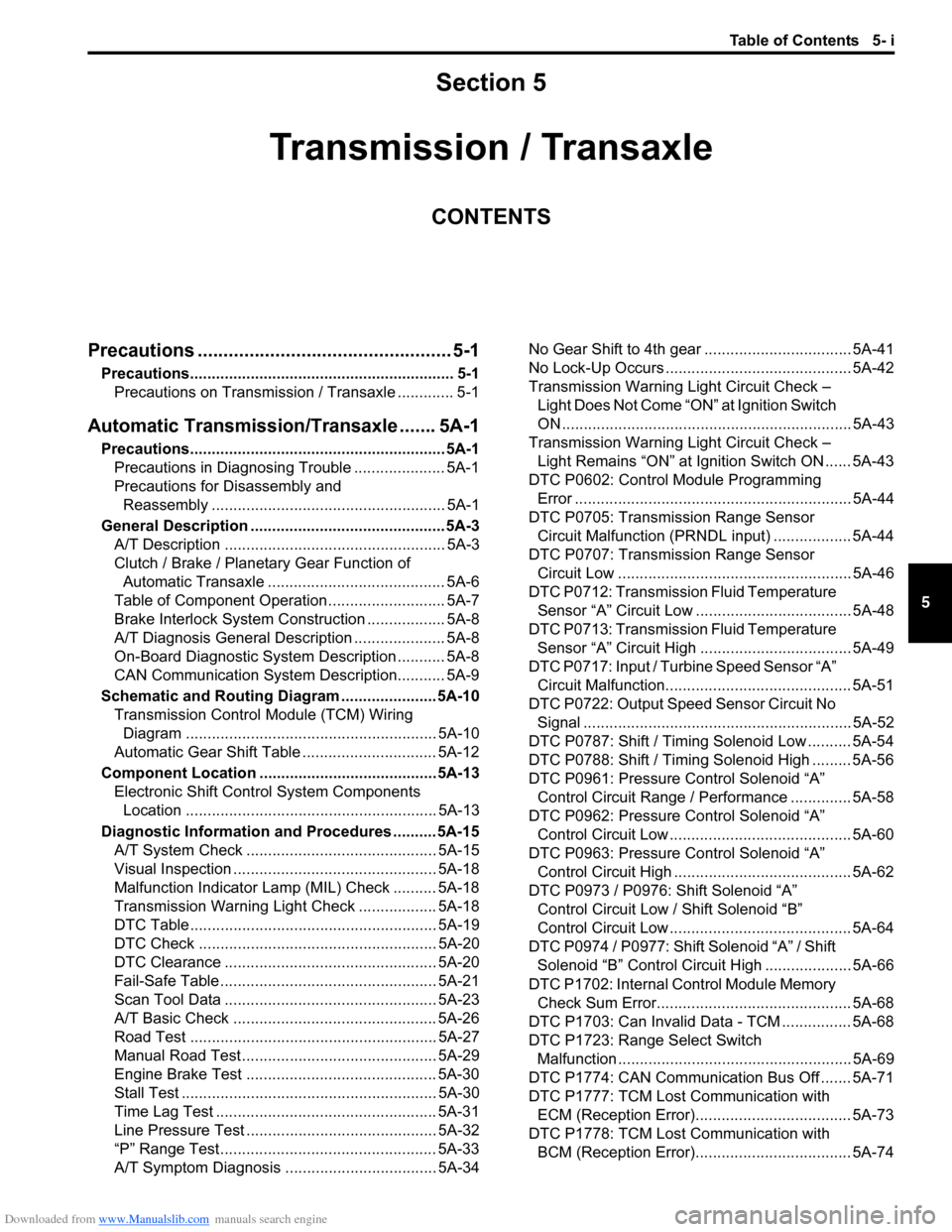
CONTENTS
Transmission / Transaxle
Precautions ................................................. 5-1
Precautions............................................................. 5-1
Precautions on Transmission / Transaxle ............. 5-1
Automatic Transmission/Transaxle ....... 5A-1
Precautions........................................................... 5A-1Precautions in Diagnosing Trouble ..................... 5A-1
Precautions for Disassembly and Reassembly ...................................................... 5A-1
General Description ............................................. 5A-3 A/T Description ................................................... 5A-3
Clutch / Brake / Planetary Gear Function of Automatic Transaxle ......................................... 5A-6
Table of Component Operation ........................... 5A-7
Brake Interlock System Construction .................. 5A-8
A/T Diagnosis General Description ..................... 5A-8
On-Board Diagnostic System Description ........... 5A-8
CAN Communication System Description........... 5A-9
Schematic and Routing Diagram ...................... 5A-10 Transmission Control Module (TCM) Wiring
Diagram .......................................................... 5A-10
Automatic Gear Shift Table ............................... 5A-12
Component Locatio n ......................................... 5A-13
Electronic Shift Cont rol System Components
Location .......................................................... 5A-13
Diagnostic Information and Procedures .......... 5A-15 A/T System Check ............................................ 5A-15
Visual Inspection ............................................... 5A-18
Malfunction Indicator Lamp (MIL) Check .......... 5A-18
Transmission Warning Ligh t Check .................. 5A-18
DTC Table ......................................................... 5A-19
DTC Check ....................................................... 5A-20
DTC Clearance ................................................. 5A-20
Fail-Safe Table ................ .................................. 5A-21
Scan Tool Data ................................................. 5A-23
A/T Basic Check ............................................... 5A-26
Road Test ......................................................... 5A-27
Manual Road Test ........... .................................. 5A-29
Engine Brake Test ............................................ 5A-30
Stall Test ........................................................... 5A-30
Time Lag Test ................................................... 5A-31
Line Pressure Test .......... .................................. 5A-32
“P” Range Test.................................................. 5A-33
A/T Symptom Diagnosis ..... .............................. 5A-34 No Gear Shift to 4th gear .................................. 5A-41
No Lock-Up Occurs ........................................... 5A-42
Transmission Warning Light Circuit Check –
Light Does Not Come “ON” at Ignition Switch
ON ................................................................... 5A-43
Transmission Warning Light Circuit Check – Light Remains “ON” at Ignition Switch ON ...... 5A-43
DTC P0602: Control Module Programming Error ................................................................ 5A-44
DTC P0705: Transmission Range Sensor Circuit Malfunction (PRNDL input) .................. 5A-44
DTC P0707: Transmission Range Sensor Circuit Low ...................................................... 5A-46
DTC P0712: Transmission Fluid Temperature Sensor “A” Circuit Low ... ................................. 5A-48
DTC P0713: Transmission Fluid Temperature Sensor “A” Circuit High .. ................................. 5A-49
DTC P0717: Input / Turbine Speed Sensor “A” Circuit Malfunction........................................... 5A-51
DTC P0722: Output Speed Sensor Circuit No Signal .............................................................. 5A-52
DTC P0787: Shift / Timing Solenoid Low .......... 5A-54
DTC P0788: Shift / Timing Solenoid High ......... 5A-56
DTC P0961: Pressure Control Solenoid “A”
Control Circuit Range / Performance .............. 5A-58
DTC P0962: Pressure Control Solenoid “A”
Control Circuit Low .......................................... 5A-60
DTC P0963: Pressure Control Solenoid “A”
Control Circuit High ......................................... 5A-62
DTC P0973 / P0976: Shift Solenoid “A” Control Circuit Low / Shift Solenoid “B”
Control Circuit Low .......................................... 5A-64
DTC P0974 / P0977: Shift Solenoid “A” / Shift Solenoid “B” Control Circuit High .................... 5A-66
DTC P1702: Internal Co ntrol Module Memory
Check Sum Error............................................. 5A-68
DTC P1703: Can Invalid Data - TCM ................ 5A-68
DTC P1723: Range Select Switch Malfunction ...................................................... 5A-69
DTC P1774: CAN Communication Bus Off ....... 5A-71
DTC P1777: TCM Lost Communication with ECM (Reception Error).................................... 5A-73
DTC P1778: TCM Lost Communication with BCM (Reception Error).................................... 5A-74
Page 670 of 1496
Downloaded from www.Manualslib.com manuals search engine 5A-26 Automatic Transmission/Transaxle:
TRANSAXLE RANGE
Transaxle range detected by signal fed from
transmission range sensor.
D RANGE SIGNAL
ON: Signal which TCM require ECM to increase idle
speed
OFF: Signal which TCM does not require ECM to
increase idle speed
THROTTLE POSITION (%)
Throttle opening ratio computed by CAN signal from
ECM.
BRAKE SWITCH
Inputted signal from brake light switch on pedal bracket.
ON: Brake pedal depressed
OFF: Brake pedal released
TORQUE REDUCTION SIGNAL
ON: Signal which TCM require ECM to reduce output
torque at shifting gear
OFF: Signal which TCM does not require ECM to reduce
output torque
ENGINE COOLANT TEMPERATURE ( °C, °F)
Engine coolant temperature computed by CAN signal
from ECM. AIR CONDITIONER SIGNAL
ON: Signal which inform that air conditioner compressor
is turned ON.
OFF: Signal which inform that air conditioner
compressor is not turned ON.
ENGINE TORQUE SIGNAL (N
⋅m)
Engine torque computed by duty pulse signal outputted
from ECM.
SLIP RPM (RPM)
This parameter indicates slip ping rotation in the torque
converter (difference between input shaft rotation and
engine rotation)
MIL REQUEST
ON: Signal which TCM requires combination meter to
turn on malfunction indicator lamp.
OFF: Signal which TCM does not require combination
meter to turn on malf unction indicator lamp.
FUEL CUT FLAG
ON: Signal which inform that fuel cut is operating.
OFF: Signal which inform that fuel cut is not operating.
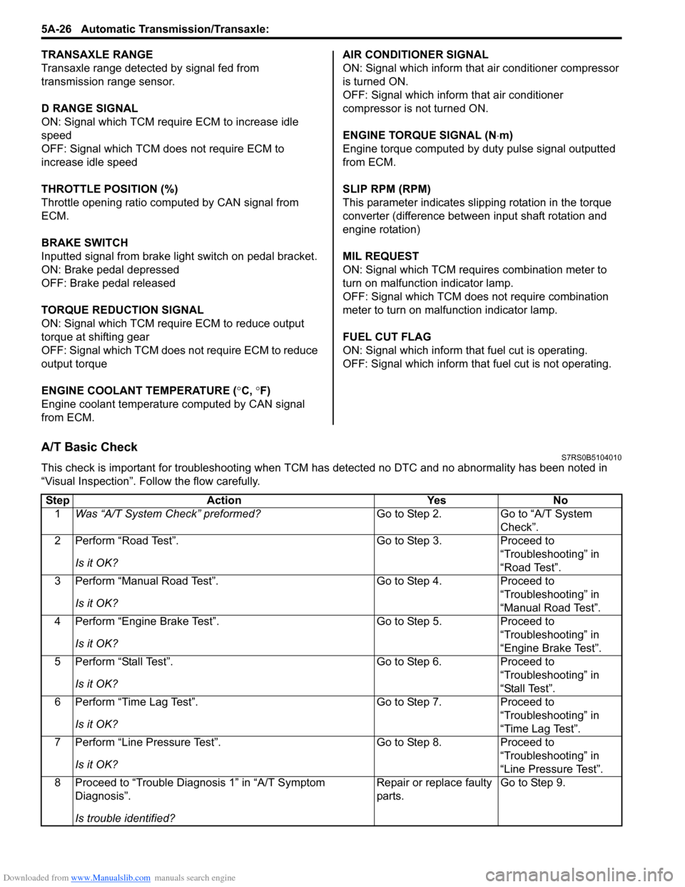
A/T Basic CheckS7RS0B5104010
This check is important for troubleshooting when TCM has detected no DTC and no abnormality has been noted in
“Visual Inspection”. Fo llow the flow carefully.
Step Action YesNo
1 Was “A/T System Check” preformed? Go to Step 2.Go to “A/T System
Check”.
2 Perform “Road Test”.
Is it OK? Go to Step 3.
Proceed to
“Troubleshooting” in
“Road Test”.
3 Perform “Manual Road Test”.
Is it OK? Go to Step 4.
Proceed to
“Troubleshooting” in
“Manual Road Test”.
4 Perform “Engine Brake Test”.
Is it OK? Go to Step 5.
Proceed to
“Troubleshooting” in
“Engine Brake Test”.
5 Perform “Stall Test”.
Is it OK? Go to Step 6.
Proceed to
“Troubleshooting” in
“Stall Test”.
6 Perform “Time Lag Test”.
Is it OK? Go to Step 7.
Proceed to
“Troubleshooting” in
“Time Lag Test”.
7 Perform “Line Pressure Test”.
Is it OK? Go to Step 8.
Proceed to
“Troubleshooting” in
“Line Pressure Test”.
8 Proceed to “Trouble Diag nosis 1” in “A/T Symptom
Diagnosis”.
Is trouble identified? Repair or replace faulty
parts.
Go to Step 9.
Page 690 of 1496
Downloaded from www.Manualslib.com manuals search engine 5A-46 Automatic Transmission/Transaxle:
Table for Step 4
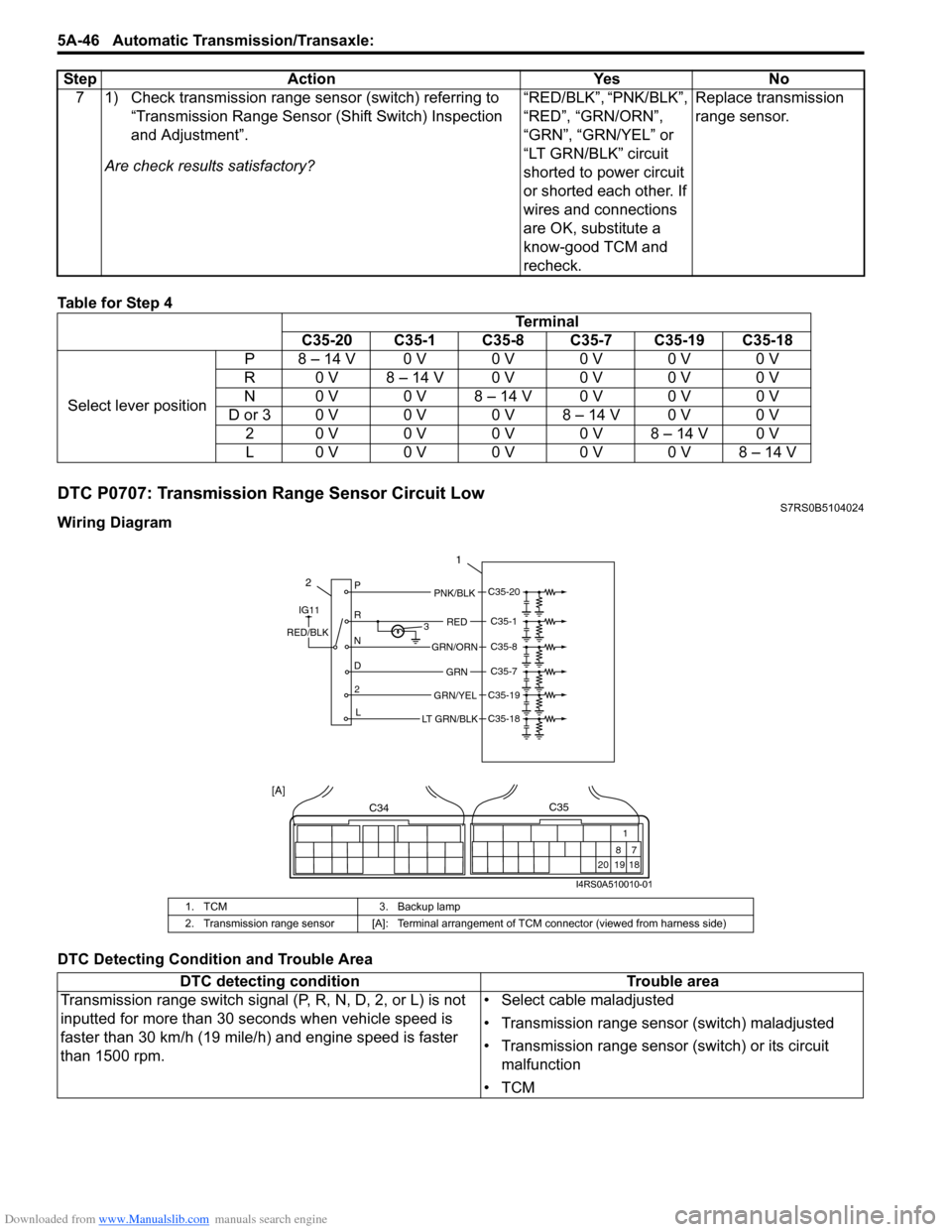
DTC P0707: Transmission Range Sensor Circuit LowS7RS0B5104024
Wiring Diagram
DTC Detecting Condition and Trouble Area7 1) Check transmission range sensor (switch) referring to
“Transmission Range Sensor (Shift Switch) Inspection
and Adjustment”.
Are check results satisfactory? “RED/BLK”, “PNK/BLK”,
“RED”, “GRN/ORN”,
“GRN”, “GRN/YEL” or
“LT GRN/BLK” circuit
shorted to power circuit
or shorted each other. If
wires and connections
are OK, substitute a
know-good TCM and
recheck.Replace transmission
range sensor.
Step Action Yes No
Terminal
C35-20 C35-1 C35-8 C35-7 C35-19 C35-18
Select lever position P 8 – 14 V 0 V 0 V 0 V 0 V 0 V
R 0 V 8 – 14 V 0 V 0 V 0 V 0 V
N 0 V 0 V 8 – 14 V 0 V 0 V 0 V
D or 3 0 V 0 V 0 V 8 – 14 V 0 V 0 V 2 0 V 0 V 0 V 0 V 8 – 14 V 0 V
L0 V0 V0 V0 V0 V8 – 14 V
1. TCM 3. Backup lamp
2. Transmission range sensor [A]: Terminal arrangem ent of TCM connector (viewed from harness side)
DTC detecting condition Trouble area
Transmission range switch signal (P, R, N, D, 2, or L) is not
inputted for more than 30 seconds when vehicle speed is
faster than 30 km/h (19 mile/h) and engine speed is faster
than 1500 rpm. • Select cable maladjusted
• Transmission range sensor (switch) maladjusted
• Transmission range sensor (switch) or its circuit
malfunction
•TCM
2P
R
N
D 2 L 3
1
PNK/BLK
RED
GRN
GRN/ORN
GRN/YEL
IG11
RED/BLK
LT GRN/BLK
C35-20
C35-1
C35-8
C35-7
C35-19
C35-18
C34
20 19
87
18
1
C35
[A]
I4RS0A510010-01
Page 992 of 1496
Downloaded from www.Manualslib.com manuals search engine 7B-44 Air Conditioning System: Automatic Type
3) Light over sunload sensor vertically with an incandescent lamp approximately 100 W apart from
about 100 mm (3.94 in.).
NOTE
If sunload sensor is not lighted over with an
incandescent lamp, DTC B1504 is detected
as current DTC even though there is not any
malfunction.
4) Turn ignition switch to ON position.
5) Erase DTC according to instructions displayed on SUZUKI scan tool.
NOTE
To know how to use SUZUKI scan tool, refer
to operator’s manual for SUZUKI scan tool.
6) After completing the clearance, turn ignition switch to OFF position, and then di sconnect SUZUKI scan
tool from DLC.
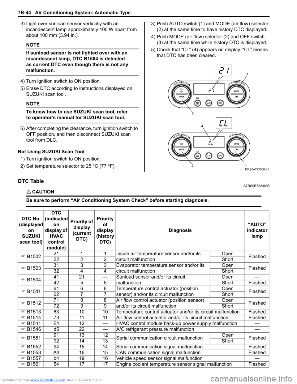
Not Using SUZUKI Scan Tool 1) Turn ignition switch to ON position.
2) Set temperature selector to 25 °C (77 °F). 3) Push AUTO switch (1) and
MODE (air flow) selector
(2) at the same time to have history DTC displayed.
4) Push MODE (air flow) selector (2) and OFF switch (3) at the same time while history DTC is displayed.
5) Check that “CL” (4) appears on display. “CL” means that DTC has been cleared.
DTC TableS7RS0B7224005
CAUTION!
Be sure to perform “Air Conditioning Sy stem Check” before starting diagnosis.
1
2
3
2
4
I5RS0A722008-01
DTC No.
(displayed on
SUZUKI
scan tool) DTC
(indicated on
display of HVAC
control
module) Priority of
display
(current DTC) Priority
of
display
(history DTC) Diagnosis
“AUTO”
indicator lamp
�) B1502 21 1 1 Inside air temperature sensor and/or its
circuit malfunction Open
Flashed
22 2 2 Short
�) B1503 31 3 3 Evaporator temperature sensor and/or its
circuit malfunction Open
Flashed
32 4 4 Short
�) B1504 41 21 — Sunload sensor and/or its circuit
malfunction Open —
42 5 5 Short Flashed
�) B1511 61 6 6 Temperature control actuator (position
sensor) and/or its circuit malfunction Open
Flashed
62 7 7 Short
�) B1512 71 8 8 Air flow control actuator (position sensor)
and/or its circuit malfunction Open
Flashed
72 9 9 Short
�) B1513 63 10 10 Temperature control actuator and/or its circuit malfunction Flashed
�) B1514 73 11 11 Air flow control actuator and/or its circuit malfunction Flashed
�) B1541 E1 12 — HVAC control module back-up power supply malfunction —
�) B1546 d5 22 — A/C refrigerant pressure malfunction —
�) B1551 91 13 12
Serial communication circuit malfunction Open
Flashed
92 14 13 Short
�) B1552 94 15 14 Serial communication signal malfunction Flashed
�) B1553 A4 16 15 CAN communication signal malfunction Flashed
�) B1557 b4 19 16 Vehicle speed sensor signal malfunction —
�) B1561 54 17 17 Engine coolant temperature sensor signal malfunction Flashed
Page 993 of 1496
Downloaded from www.Manualslib.com manuals search engine Air Conditioning System: Automatic Type 7B-45
NOTE
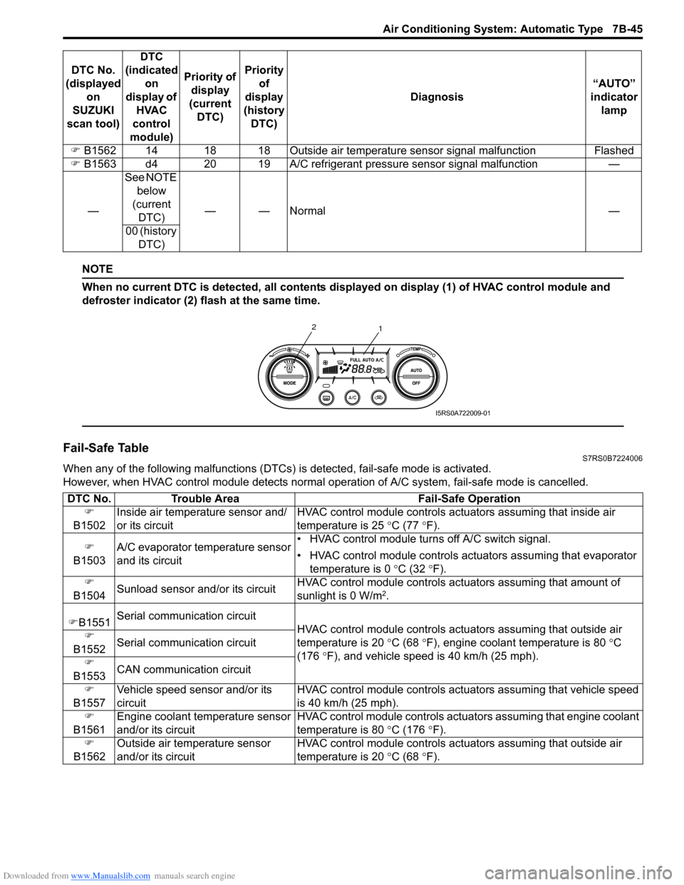
When no current DTC is detected, all contents displayed on display (1) of HVAC control module and
defroster indicator (2) flash at the same time.
Fail-Safe TableS7RS0B7224006
When any of the following malfunctions (DTCs) is detected, fail-safe mode is activated.
However, when HVAC control module detects normal ope ration of A/C system, fail-safe mode is cancelled.
�)
B1562 14 18 18 Outside air temperatur e sensor signal malfunction Flashed
�) B1563 d4 20 19 A/C refrigerant pressure sensor signal malfunction —
— See NOTE
below
(current DTC) ——Normal —
00 (history DTC)
DTC No.
(displayed on
SUZUKI
scan tool) DTC
(indicated on
display of HVAC
control
module) Priority of
display
(current DTC) Priority
of
display
(history DTC) Diagnosis
“AUTO”
indicator lamp
1
2
I5RS0A722009-01
DTC No.
Trouble Area Fail-Safe Operation
�)
B1502 Inside air temperature sensor and/
or its circuit HVAC control module controls actu
ators assuming that inside air
temperature is 25 ° C (77 °F).
�)
B1503 A/C evaporator temperature sensor
and its circuit • HVAC control module turn
s off A/C switch signal.
• HVAC control module controls actu ators assuming that evaporator
temperature is 0 ° C (32 °F).
�)
B1504 Sunload sensor and/or its circuit HVAC control module controls actu
ators assuming that amount of
sunlight is 0 W/m
2.
�) B1551 Serial communication circuit
HVAC control module controls actuators assuming that outside air
temperature is 20 ° C (68 °F), engine coolant temperature is 80 °C
(176 °F), and vehicle speed is 40 km/h (25 mph).
�)
B1552 Serial communication circuit
�)
B1553 CAN communication circuit
�)
B1557 Vehicle speed sensor and/or its
circuit HVAC control module controls act
uators assuming that vehicle speed
is 40 km/h (25 mph).
�)
B1561 Engine coolant temperature sensor
and/or its circuit HVAC control module controls act
uators assuming that engine coolant
temperature is 80 ° C (176 °F).
�)
B1562 Outside air temperature sensor
and/or its circuit HVAC control module controls actu
ators assuming that outside air
temperature is 20 ° C (68 °F).
Page 995 of 1496
Downloaded from www.Manualslib.com manuals search engine Air Conditioning System: Automatic Type 7B-47
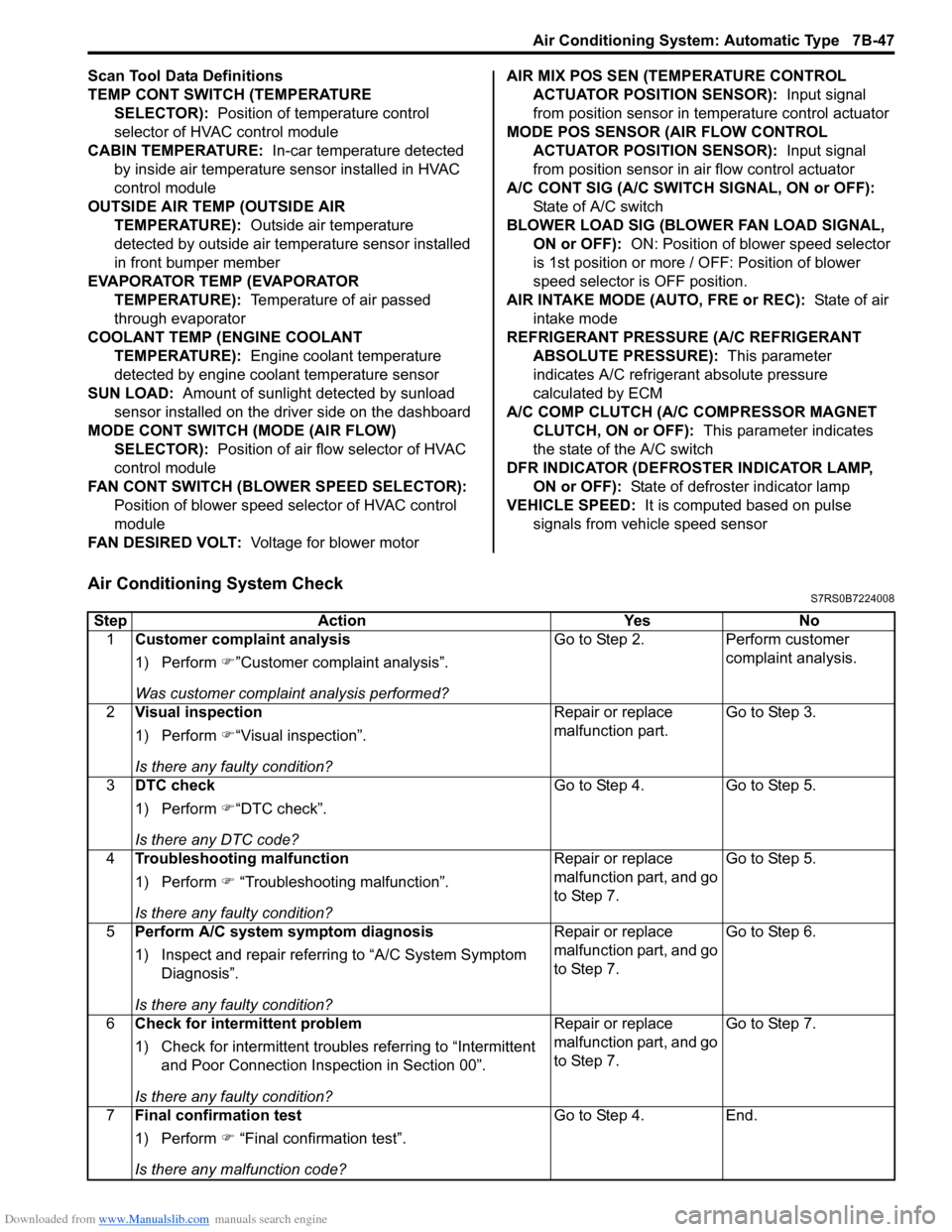
Scan Tool Data Definitions
TEMP CONT SWITCH (TEMPERATURE SELECTOR): Position of temperature control
selector of HVAC control module
CABIN TEMPERATURE: In-car temperature detected
by inside air temperature sensor installed in HVAC
control module
OUTSIDE AIR TEMP (OUTSIDE AIR TEMPERATURE): Outside air temperature
detected by outside air temperature sensor installed
in front bumper member
EVAPORATOR TEMP (EVAPORATOR TEMPERATURE): Temperature of air passed
through evaporator
COOLANT TEMP (ENGINE COOLANT TEMPERATURE): Engine coolant temperature
detected by engine coolant temperature sensor
SUN LOAD: Amount of sunlight detected by sunload
sensor installed on the driver side on the dashboard
MODE CONT SWITCH (MODE (AIR FLOW) SELECTOR): Position of air flow selector of HVAC
control module
FAN CONT SWITCH (BLOWER SPEED SELECTOR): Position of blower speed selector of HVAC control
module
FAN DESIRED VOLT: Voltage for blower motor AIR MIX POS SEN (TEMPERATURE CONTROL
ACTUATOR POSITI ON SENSOR): Input signal
from position sensor in temperature control actuator
MODE POS SENSOR (AIR FLOW CONTROL ACTUATOR POSITI ON SENSOR): Input signal
from position sensor in air flow control actuator
A/C CONT SIG (A/C SWITCH SIGNAL, ON or OFF): State of A/C switch
BLOWER LOAD SIG (BLO WER FAN LOAD SIGNAL,
ON or OFF): ON: Position of blower speed selector
is 1st position or more / OFF: Position of blower
speed selector is OFF position.
AIR INTAKE MODE (AUTO, FRE or REC): State of air
intake mode
REFRIGERANT PRESSURE (A/C REFRIGERANT ABSOLUTE PRESSURE): This parameter
indicates A/C refrigerant absolute pressure
calculated by ECM
A/C COMP CLUTCH (A/C COMPRESSOR MAGNET CLUTCH, ON or OFF): This parameter indicates
the state of the A/C switch
DFR INDICATOR (DEFROSTER INDICATOR LAMP, ON or OFF): State of defroster indicator lamp
VEHICLE SPEED: It is computed based on pulse
signals from vehicle speed sensor
Air Conditioning System CheckS7RS0B7224008
Step Action YesNo
1 Customer complaint analysis
1) Perform �)”Customer complaint analysis”.
Was customer complaint analysis performed? Go to Step 2.
Perform customer
complaint analysis.
2 Visual inspection
1) Perform �)“Visual inspection”.
Is there any faulty condition? Repair or replace
malfunction part.
Go to Step 3.
3 DTC check
1) Perform �)“DTC check”.
Is there any DTC code? Go to Step 4.
Go to Step 5.
4 Troubleshooting malfunction
1) Perform �) “Troubleshooting malfunction”.
Is there any faulty condition? Repair or replace
malfunction part, and go
to Step 7.
Go to Step 5.
5 Perform A/C system symptom diagnosis
1) Inspect and repair referri ng to “A/C System Symptom
Diagnosis”.
Is there any faulty condition? Repair or replace
malfunction part, and go
to Step 7.
Go to Step 6.
6 Check for intermittent problem
1) Check for intermittent troubles referring to “Intermittent
and Poor Connection Inspection in Section 00”.
Is there any faulty condition? Repair or replace
malfunction part, and go
to Step 7.
Go to Step 7.
7 Final confirmation test
1) Perform �) “Final confirmation test”.
Is there any malfunction code? Go to Step 4.
End.
Page 1051 of 1496
Downloaded from www.Manualslib.com manuals search engine Air Bag System: 8B-13
Scan Tool DataS7RS0B8204006
Data list of SDM
Definition
Back Up Volt (V)
This parameter indicates the capacity of the backup
condenser installed to maintain the ignition current (as
much as possible) even when the power supply to SDM
that ignites the inflator is shut off.
Battery Voltage (V)
Battery voltage is an analog input signal read by SDM.
System ID (4ch/8ch)
This parameter indicates the number of initiator circuits.
Driv A/B Ini Res (Driver air bag initiator resistance)
(ohm)
This parameter indicates the resistance of the driver air
bag initiator circuit. Pass A/B Ini Res (Passenger air bag initiator
resistance) (ohm)
This parameter indicates the
resistance of the passenger
air bag initiator circuit.
Driv Preten Ini Res (Dri ver pretensioner initiator
resistance) (ohm)
This parameter indicates the resistance of the driver seat
belt pretensioner initiator circuit.
Pass Preten Ini Res (Passenger pretensioner
initiator resistance) (ohm)
This parameter indicates the resistance of the passenger
seat belt pretensioner initiator circuit.
Driv Sidebag Ini Res (Driver side-air bag initiator
resistance) (ohm)
This parameter indicates the resistance of the driver
side-air bag initiator circuit.
Pass Sidebag Ini Res (Passenger side-air bag
initiator resistance) (ohm)
This parameter indicates the resistance of the
Passenger side-air bag initiator circuit.
Driv curtain Ini Res (Driver side curtain-air bag
initiator resistance) (ohm)
This parameter indicates the re sistance of the driver side
curtain-air bag initiator circuit.
Pass curtain Ini Res (Passenger side curtain-air bag
initiator resistance) (ohm)
This parameter indicates the resistance of the passenger
side curtain-air bag initiator circuit.
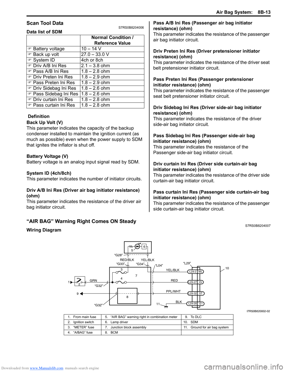
“AIR BAG” Warning Right Comes ON SteadyS7RS0B8204007
Wiring Diagram Normal Condition /
Reference Value
�) Battery voltage 10 – 14 V
�) Back up volt 27.0 – 33.0 V
�) System ID 4ch or 8ch
�) Driv A/B Ini Res 2.1 – 3.8 ohm
�) Pass A/B Ini Res 1.8 – 2.8 ohm
�) Driv Preten Ini Res 1.8 – 2.9 ohm
�) Pass Preten Ini Res 1.8 – 2.9 ohm
�) Driv Sidebag Ini Res 1.8 – 2.6 ohm
�) Pass Sidebag Ini Res 1.8 – 2.6 ohm
�) Driv curtain Ini Res 1.8 – 2.8 ohm
�) Pass curtain Ini Res 1.8 – 2.8 ohm
1
2 GRN
11
BLK
L29-27
L29-2
L29-28 WL
E1
IG
L29-32
ST
10
8
“L29”
RED
PPL/WHT
7
3
4 “L04”
“G34”
“G33”
“G28”
“G32”
5 6
“G32”
YEL/BLK
YEL/BLK
RED/BLK
9
I7RS0B820002-02
1. From main fuse 5. “AIR BAG” warning right in combination meter 9. To DLC
2. Ignition switch 6. Lamp driver 10. SDM
3. “METER” fuse 7. Junction block assembly 11. Ground for air bag system
4. “A/BAG” fuse 8. BCM
Page 1210 of 1496
Downloaded from www.Manualslib.com manuals search engine 9A-39 Wiring Systems:
1IG2FL2
6
Lamp FL (FL BOX)
1A/B CONT4A/B SIG
3K-LINE2A/B SIGNAL
9A/B SIGNAL8K-LINE
2311BCM ;IG1
22D/UL-IN21D/L-IN D/SL-IN
18SECURITY IN6Serial OUT
14TAIL BCM WNG, etc12ANSWER BACK
17RR DEF CONTROL1D/L (+B)
2BCM15DEICER CONTROL
10ACC (BCM)7DOME LP CONT
20GND (POWER)16R-WIP (CONT)
3SIGNAL GND (BCM)
7IG
1LP-L5LP-R
8+B6SW-L
3GND4SW-R
2HAZ
DOME LP POWER5DOME LP DOOR4*3GND (Roof)6HTR4Starter SW1IG 25ACC SW3IG2SW2IG 1
18107G33415G347G3419G341G3412G339G3311G343G342G348G34166G336G345G33810511G3313G344G341G3320G342G339G343G3312G3414G34
10E395E4112E419E4114E411E418E412E4111E413E416E395E3916E417E414E392E399E393E397E3910E41
DEF LP
RR FOG SW DEICER LP
*TAIL SW (Upper)
TAIL SW (HAZ,ASH,ILL) TURN-L
TURN-R
METER (L)
METER (R)
HAZARD SW HORN SW
Serial INF DISP
A/C PANEL
*MTR Power,etc
IMMOBI IG
A/C PANEL
*
*
RADIO, CLOCK
A/B SIGCIGAR
*F-WIP*
*GND (IP)
SIGNAL GND (IP)
*
*
*
IG Coil, etc EPS AT
ABS CONT
BACK (SHIFT) STOP SW
ABS CONT EPI
BUL IN
HORN
FR TURN (R)
FR TURN (L) POSI LP
EPI
DEICER
*F-Washer
F.WIP
HTR Fuse (30A)
ST RLY COIL
4L0515L0516L055L059L05212L0513L0614L067L0615L0614L0511L056L065L068L057L056L0518L053L051L0510L059L0610L061L063L062L068L0611L064L06
SIGNAL GND (FL)
SEAT HEATER
P/W
R-WIP (+) R-WIP (-)*
ACC SOCKET
R/C MIR (ACC)
*
*
*
LUGGAGE LAMPMTA SHIFT LEVER SW
*
*
RR DEF
HTR MIR (L)
HTR MIR (R)
P/W DR
TAIL LP, LICENSE
R-TURN (L)
RR-TURN (R)
D/ULD/L
D-SL
BUL-L
STOP LP
MTA
*
*
IG COIL 15AMETER 10A A/BAG 15A
IG1 SIG 10A ABS 10A
BACK 10A
TAIL 10AD/L 20A
P/WT 20A
RR DEF 20A
DEICER/RR FOG 15A
MTA/HID R 10A
ACC 1 15A
ACC 2 15A
WIPER 15A P/W 30A
*Spare-1
SEAT HTR 15A IG2 SIG 10AST SIG 10A
HAZ-HORN 15A
DIESEL/HID L 10A *Spare-2 RR DEF RLY
DEICER RLY HORN RLY
P-WIP RLY
BLOWER MOTOR RLY
G34 G34
G33
G34
G33
G34 G33
L05
RADIO 15A
To instrument panel harness
(G32) To roof harness
(K01)
To instrument panel
harness
(G33 , G34 )
To main harness
(E39 , E41) To floor harness (L05 , L06 ) To main
harness
(E40)
BCM
To flasher
relay To floor
harness
(L04)
* : Not used
I7RS0B910949-01