2006 SUZUKI SWIFT D-4
[x] Cancel search: D-4Page 1167 of 1496

Downloaded from www.Manualslib.com manuals search engine Table of Contents 9- i
9
Section 9
CONTENTS
Body, Cab and Accessories
Precautions ................................................. 9-1
Precautions............................................................. 9-1
Precautions on Body, Cab and Accessories ......... 9-1
Precautions for Body Service ................................ 9-1
Fastener Caution for Body Service ....................... 9-1
Wiring Systems............... ......................... 9A-1
Precautions........................................................... 9A-1
Cautions in Body Electrical System Servicing..... 9A-1
General Description ............................................. 9A-1 Abbreviations ...................................................... 9A-1
Wire / Connector Color Sy mbols ......................... 9A-1
Symbols and Marks ............................................ 9A-2
How to Read Connector Layout Diagram ........... 9A-4
How to Read Connector Codes and Terminal Nos.................................................................... 9A-5
How to Read Ground Point ................................. 9A-7
How to Read Power Supply Diagram.................. 9A-8
How to Read System Circuit Diagram................. 9A-8
Connector Layout Diagram . .............................. 9A-10
Connector Layout Diagram ............................... 9A-10
Engine Compartment .......... .............................. 9A-10
Instrument Panel ............................................... 9A-16
Door, Roof......................................................... 9A-20
Floor .................................................................. 9A-23
Rear .................................................................. 9A-29
Ground Point ...................................................... 9A-30 Ground (earth) Point ......................................... 9A-30
Power Supply Diagram ........ .............................. 9A-31
Power Supply Diagram ....... .............................. 9A-31
Fuses and the Protected Parts ......................... 9A-33
Fuses in Main Fuse Box (RHD) ........................ 9A-33
Fuses in Main Fuse Box (LHD) ......................... 9A-33
Individual Circuit Fuse Box No. 1 ...................... 9A-34
Individual Circuit Fuse Box No. 2 (In J/B) ......... 9A-35
Junction Block (J/B) Connector / Fuse Layout .. 9A-37
Junction Block Inner Circuit (Overview) ............ 9A-38
Junction Block Inner Circuit (Detail) .................. 9A-40
System Circuit Diagram... .................................. 9A-45
System Circuit Diagram .. .................................. 9A-45
A-1 Cranking System Circ uit Diagram .............. 9A-46
A-2 Charging System Circu it Diagram .............. 9A-47
A-3 Ignition System Circu it Diagram ................. 9A-48
A-4 Cooling System Circuit Diagram................. 9A-49 A-5 Engine and A/C Control System Circuit
Diagram........................................................... 9A-50
A-6 A/T Control System Circuit Diagram........... 9A-55
A-7 Immobilizer System Circuit Diagram .......... 9A-57
A-8 Body Control System Circuit Diagram ........ 9A-58
B-1 Windshield Wiper and Washer Circuit Diagram........................................................... 9A-62
B-2 Rear Wiper and Washer Circuit Diagram ... 9A-63
B-3 Rear Defogger Circuit Diagram .................. 9A-64
B-4 Power Window Circuit Diagram .................. 9A-65
B-5 Power Door Lock Circu it Diagram .............. 9A-67
B-6 Power Mirror Circuit Diagram ..................... 9A-69
B-7 Horn Circuit Diagram .................................. 9A-70
B-8 Seat Heater Circuit Diagram....................... 9A-71
B-9 Keyless Start System Circuit Diagram........ 9A-72
C-1 Combination Mete r Circuit Diagram
(Meter)............................................................. 9A-73
C-2 Combination Mete r Circuit Diagram
(Indicator) ........................................................ 9A-74
C-3 Combination Mete r Circuit Diagram
(Warning Light)................................................ 9A-75
D-1 Headlight System Circuit Diagram ............. 9A-77
D-2 Position, Tail and Licence Plate Light System Circuit Diagram .................................. 9A-79
D-3 Front Fog Light System Circuit Diagram .... 9A-80
D-4 Illumination Light System Circuit Diagram .. 9A-81
D-5 Interior Light System Circuit Diagram......... 9A-82
D-6 Turn Signal and Hazard Warning Light System Circuit Diagram .................................. 9A-83
D-7 Brake Light System Circuit Diagram .......... 9A-85
D-8 Back-Up Light System Circuit Diagram ...... 9A-86
D-9 Headlight Beam Leveling System Circuit Diagram........................................................... 9A-87
D-10 Rear Fog Light Circuit Diagram ................ 9A-88
E-1 Heater System Circuit Diagram .................. 9A-89
E-2 Auto A/C System Circuit Diagram .............. 9A-91
F-1 Air-Bag System Circuit Diagram ................. 9A-93
F-2 Anti-Lock Brake System Circuit Diagram.... 9A-95
F-3 Electronic Stab ility Program System
Circuit Diagram .................. ............................. 9A-97
F-4 Power Steering System Circuit Diagram .... 9A-99
G-1 Audio System Circuit Diagram ................. 9A-101
G-2 Multi Information Display / Accessory Socket System Circuit Diagram .................... 9A-102
List of Connector .............................................9A-103
Page 1169 of 1496

Downloaded from www.Manualslib.com manuals search engine Table of Contents 9-iii
Door Switch (Front / Rear Door) Inspection ...... 9C-17
Rear End Door Switch Inspection ..................... 9C-17
Outside Air Temperature Sensor Removal and Installation (If Equipped) .......................... 9C-17
Outside Air Temperature Sensor Inspection (If Equipped) ................................................... 9C-17
Instrument Panel Removal and Installation....... 9C-18
Information Display (Clock) Removal and Installation ....................................................... 9C-19
Audio Unit Removal and In stallation ................. 9C-19
Front Speaker Removal and Installation ........... 9C-19
Rear Speaker Removal and Installation............ 9C-20
Horn Removal and Installation .......................... 9C-20
Horn Inspection ................................................. 9C-20
Horn Relay Inspection ....................................... 9C-20
Antenna Amplifier Removal and Installation ..... 9C-21
Remote Audio Control Switch Removal and Installation (If Equipped) ................................. 9C-21
Remote Audio Control Switch Inspection (If Equipped)........................................................ 9C-22
Vehicle Speed Signal Inspection (For Audio Unit) (If Equipped) ........................................... 9C-22
Specifications ..................................................... 9C-22
Tightening Torque Specifications ...................... 9C-22
Wipers / Washers............ ......................... 9D-1
Diagnostic Information and Procedures ............ 9D-1
Front Wiper and Washer Symptom Diagnosis .... 9D-1
Rear Wiper and Washer Symptom Diagnosis..... 9D-1
Repair Instructions .............................................. 9D-2 Wipers and Washers Components ..................... 9D-2
Washer Tank and Washer Pump Removal and Installation .................................................. 9D-3
Washer Pump Inspection .................................... 9D-3
Windshield Wiper Removal and Installation ........ 9D-4
Windshield Wiper Motor Inspection..................... 9D-5
Rear Wiper Removal and Installation.................. 9D-6
Rear Wiper Motor Inspection .............................. 9D-7
Windshield Wiper and Washer Switch Removal and Installation................................... 9D-7
Windshield Wiper and Washer Switch Inspection.......................................................... 9D-8
Rear Wiper and Washer Switch Removal and Installation ......................................................... 9D-9
Rear Wiper and Washer Switch Inspection......... 9D-9
Rear Wiper Relay Removal and Installation ..... 9D-10
Rear Wiper Relay Inspection ............................ 9D-10
Specifications ..................................................... 9D-10
Tightening Torque Specifications ...................... 9D-10
Glass / Windows / Mirrors.. ..................... 9E-1
General Description ............................................. 9E-1
Rear End Door Window Defogger System Description ........................................................ 9E-1
Windshield Construction ..................................... 9E-1
Diagnostic Information and Procedures ............ 9E-2 Rear End door Window Defogger Symptom Diagnosis .......................................................... 9E-2 Power Window Control System Symptom
Diagnosis .......................................................... 9E-2
Power Door Mirror Control System Symptom Diagnosis .......................................................... 9E-3
Door Mirror Heater Symptom Diagnosis (If
Equipped) .......................................................... 9E-3
Repair Instructions ........... ................................... 9E-4
Windshield Removal and In stallation .................. 9E-4
Front Door Window Components ........................ 9E-8
Front Door Glass Removal and Installation ........ 9E-8
Front Door Window Re gulator Removal and
Installation ......................................................... 9E-9
Front Door Window Regula tor Inspection ......... 9E-10
Rear Door Window Components ...................... 9E-10
Rear Door Glass Removal and Installation ....... 9E-11
Rear Door Window Regulator Removal and Installation ....................................................... 9E-12
Rear Door Window Regulato r Inspection .......... 9E-12
Rear End Door Window Components ............... 9E-13
Rear End Door Glass Removal and Installation ....................................................... 9E-13
Rear End Door Window Defogger Switch Inspection ........................................................ 9E-14
Rear End Door Window Defogger Relay Inspection ........................................................ 9E-14
Rear End Door Window Defogger Wire Inspection ........................................................ 9E-15
Rear End Door Window Defogger Wire
Repair.............................................................. 9E-15
Power Window Main Switch Inspection ............ 9E-16
Power Window Sub Switch Inspection .............. 9E-17
Door Mirror Components.. ................................. 9E-18
Door Mirror Removal and In stallation................ 9E-18
Power Door Mirror Switch Inspection ................ 9E-18
Power Door Mirror Actuator Inspection ............. 9E-19
Door Mirror Heater Switch Inspection (If Equipped) ........................................................ 9E-19
Door Mirror Heater Inspec tion (If Equipped) ..... 9E-19
Special Tools and Equipmen t ........................... 9E-19
Recommended Service Material ....................... 9E-19
Security and Locks......... ..........................9F-1
General Description ............................................. 9F-1
Key Coding Construction .................................... 9F-1
Rear End Door Opener System Description ....... 9F-1
Component Location ............ ............................... 9F-2
Power Door Lock and Keyless Entry System
Component Location ......................................... 9F-2
Diagnostic Information and Procedures ............ 9F-3 Power Door Lock System Symptom Diagnosis .......................................................... 9F-3
Power Door Lock System Operation Inspection .......................................................... 9F-3
Keyless Entry System Symptom Diagnosis (If
Equipped) .......................................................... 9F-4
Keyless Entry System Operation Inspection ....... 9F-5
Door Lock Function of Keyless Start System Symptom Diagnosis (If Equipped)..................... 9F-5
Page 1216 of 1496

Downloaded from www.Manualslib.com manuals search engine 9A-45 Wiring Systems:
System Circuit Diagram
System Circuit DiagramS7RS0B910E001
Refer to “A-1 Cranking System Circuit Diagram”.
Refer to “A-2 Charging System Circuit Diagram”.
Refer to “A-3 Ignition System Circuit Diagram”.
Refer to “A-4 Cooling System Circuit Diagram”.
Refer to “A-5 Engine and A/C Control System Circuit Diagram”.
Refer to “A-6 A/T Control System Circuit Diagram”.
Refer to “A-7 Immobilizer System Circuit Diagram”.
Refer to “A-8 Body Control System Circuit Diagram”.
Refer to “B-1 Windshield Wiper and Washer Circuit Diagram”.
Refer to “B-2 Rear Wiper and Washer Circuit Diagram”.
Refer to “B-3 Rear Defogger Circuit Diagram”.
Refer to “B-4 Power Window Circuit Diagram”.
Refer to “B-5 Power Door Lock Circuit Diagram”.
Refer to “B-6 Power Mi rror Circuit Diagram”.
Refer to “B-7 Horn Circuit Diagram”.
Refer to “B-8 Seat Heater Circuit Diagram”.
Refer to “B-9 Keyless Star t System Circuit Diagram”.
Refer to “C-1 Combination Me ter Circuit Diagram (Meter)”.
Refer to “C-2 Combination Mete r Circuit Diagram (Indicator)”.
Refer to “C-3 Combination Meter Circuit Diagram (Warning Light)”.
Refer to “D-1 Headlight System Circuit Diagram”.
Refer to “D-2 Position, Tail and Licence Plate Light System Circuit Diagram”.
Refer to “D-3 Front Fog Light System Circuit Diagram”.
Refer to “D-4 Illumination Light System Circuit Diagram”.
Refer to “D-5 Interior Li ght System Circuit Diagram”.
Refer to “D-6 Turn Signal and Hazard Warning Light System Circuit Diagram”.
Refer to “D-7 Brake Light System Circuit Diagram”.
Refer to “D-8 Back-Up Light System Circuit Diagram”.
Refer to “D-9 Headlight Beam Leveling System Circuit Diagram”.
Refer to “D-10 Rear Fog Light Circuit Diagram”.
Refer to “E-1 Heater System Circuit Diagram”.
Refer to “E-2 Auto A/C System Circuit Diagram”.
Refer to “F-1 Air-Bag System Circuit Diagram”.
Refer to “F-2 Anti-Lock Brake System Circuit Diagram”.
Refer to “F-3 Electronic Stabilit y Program System Circuit Diagram”.
Refer to “F-4 Power Steeri ng System Circuit Diagram”.
Refer to “G-1 Audio Sy stem Circuit Diagram”.
Refer to “G-2 Multi Information Display / Accessory Socket System Circuit Diagram”.
Page 1230 of 1496
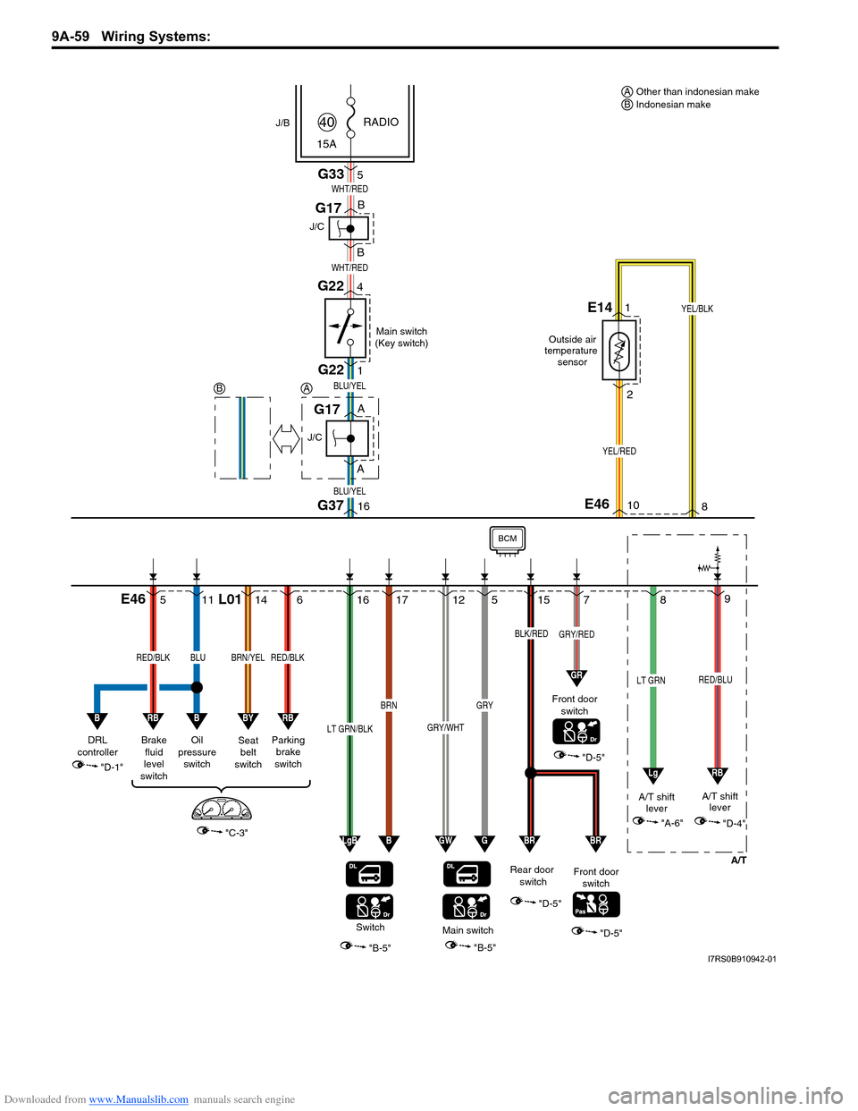
Downloaded from www.Manualslib.com manuals search engine 9A-59 Wiring Systems:
9
15 7
"D-5"
"A-6"
A/T
GRY/RED
RED/BLU
16
A A
B
BG37
BLU/YEL
BLU/YEL
J/C
G17
J/C
G17
G22
G22
1
4
Main switch
(Key switch)
RADIO
G335
15A
40
WHT/RED
WHT/RED
YEL/RED
YEL/BLK1E14
2
Outside air
temperature sensor
"B-5"
Switch
6L0114
1617125
RED/BLKBRN/YEL
LT GRN/BLK
BRN
GRY/WHT
GRY
Parking
brake
switch
Seat
belt
switch
"C-3"
"D-1"
RBBY
8
LT GRN
A/T shift lever A/T shift
lever
115
"D-4"
LgRB
GR
Oil
pressure switchBrakefluid
level
switch
B
DRL
controller
B
E46
10E468
LgBBGWG
Main switch
"B-5"
Front door switch
Front door switch
Rear door switch
"D-5"
"D-5"
BRBR
BLK/RED
J/B
BCM
BLURED/BLK
RB
Other than indonesian make
Indonesian make
A
AB
B
I7RS0B910942-01
Page 1232 of 1496
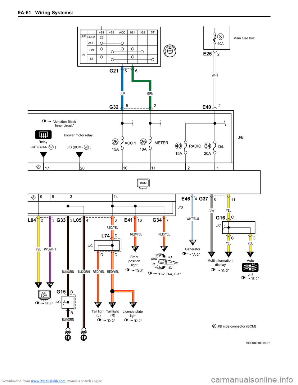
Downloaded from www.Manualslib.com manuals search engine 9A-61 Wiring Systems:
50A
3
J/B
15ARADIO
40
2
15A
ACC 1
26
10
1
20AD/L
34
11
10A
METER
25
Main fuse box
WHT
E402
20
Blower motor relay
"Junction Block Inner circuit"
Relay
J/B (BCM- 20 )J/B (BCM- 17 )
17
2L04
9
3
83
B BG33
3
4L05
10
J/C
G15
BLK/ORN
BLK/ORN
16
BLK/ORN
"F-1"
YELPPL/WHT
A/B
SDM
14
316E417G34
Front
position light
"D-2"
"D-2, D-4, G-1"
J/B
RED/YELRED/YEL
J/C
L74D
DD
Licence plate light
"D-2"
YPW
"A-2"
Generator
E464
WHT/BLU
WB
RYRY
RYRYRY
Tail light
(R)
Tail light
(L)
"D-2"
RED/YEL
RED/YEL
RED/YEL
811
C CG37
J/C
G16
YEL
GRYYEL
GY
C
YEL
Y
"G-2"
Multi information
display Auto
unit
"E-2"
A
A
J/C
2E26
+B1
LOCK
ACC
ON
ST ACC IG1 IG2
STOUT
IN
+B2
BLUGRN
G3252
56G21
J/B side connector (BCM)
A
BCM
I7RS0B910919-01
Page 1242 of 1496
Downloaded from www.Manualslib.com manuals search engine 9A-71 Wiring Systems:
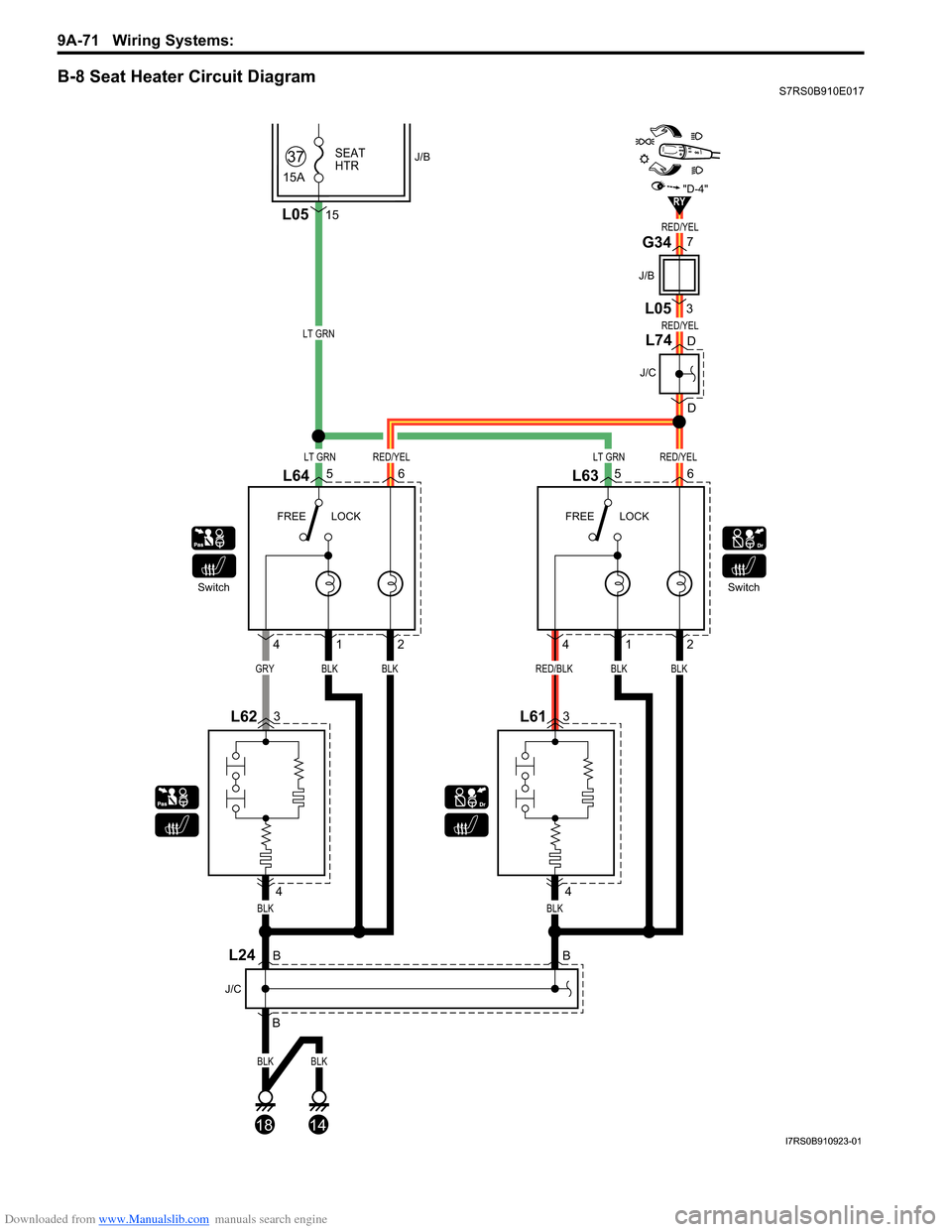
B-8 Seat Heater Circuit DiagramS7RS0B910E017
LT GRN
LT GRNLT GRNRED/YEL
RED/YEL
RED/YEL
RED/YEL
GRYBLK
L6456
L623
4
4
12
L635
18
L613
4
BLKRED/BLKBLK
412
BLK
BLK
BLK
14
BLK
BLK
Switch FREE LOCK FREE LOCKSwitch
L0515
15A
SEAT
HTR37J/B
6
RY"D-4"
7
3
J/B
G34 L05
B
BB
J/C
L24
D D
J/C
L74
I7RS0B910923-01
Page 1248 of 1496
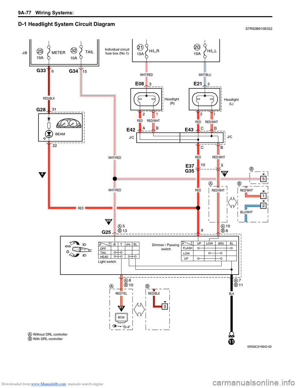
Downloaded from www.Manualslib.com manuals search engine 9A-77 Wiring Systems:
D-1 Headlight System Circuit DiagramS7RS0B910E022
1
Headlight (R) Headlight
(L)
WHT/BLU
RED
Dimmer / Passing switch
Light switch
2
2
BA BC
B
C
33
15
1
22G28
E08
G34
E21
G336
31
RED/BLK
WHT/RED
WHT/RED
10A
25METER
WHT/RED
9
BLK
11
G25
15A
21
15A
20H/L,R H/L,L
RED/WHTRED
10
RED
RED
J/B
10ATAIL
32
RED/WHTRED/WHT
BLU/WHT
5
RED/WHT
E37
G35
E42
J/C
REDRED/WHT
BEAM
FLASH UPLOW
T
P(ED)EL
UP
LOW
OFF
TAIL
HEAD -BT
T
P(H) EL
RY
RED/YEL
"D-4"
BCM
R
WR
RW
E43
J/C
Individual circuit
fuse box (No.1)
Without DRL controller
AWith DRL controller
B
A
5
1
2
3
AB
B
RED/BLK
B
AB5
13AB10
8
AB7
11AB8
10
I5RS0C910942-02
Page 1249 of 1496
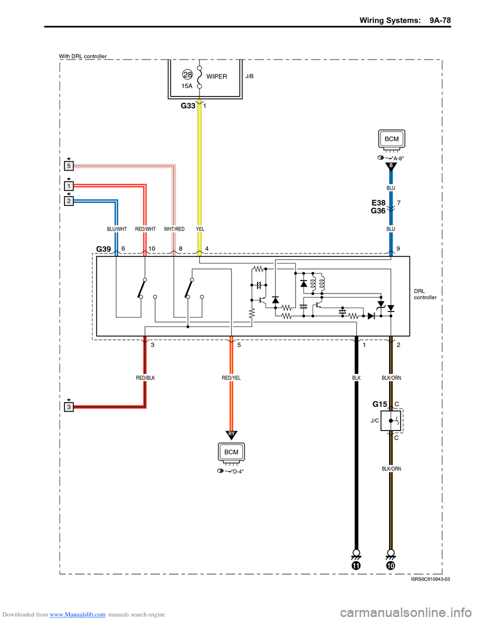
Downloaded from www.Manualslib.com manuals search engine Wiring Systems: 9A-78
YELRED/WHT
RED/BLK
3
RED/YEL
5
7 E38 G36
15A WIPER
28
DRL
controller
G3910
WHT/RED
8
BLU/WHT
6
G331
4
9
BLU
BLU
BLK/ORN
BLK/ORN
2
BLK
1
"A-8"
1
5
2
3
B
RY
J/B
BCM
"D-4"
BCM
1110
C
C
J/C
With DRL controller
G15
I5RS0C910943-03