2006 SUZUKI SWIFT eco
[x] Cancel search: ecoPage 974 of 1496
Downloaded from www.Manualslib.com manuals search engine 7B-26 Air Conditioning System: Manual Type
Expansion Valve Removal and InstallationS7RS0B7216010
Removal1) Recover refrigerant fr om the A/C system with
recovery and recycling equipment referring to
“Recovery” in “Operation Procedure for Refrigerant
Charge”.
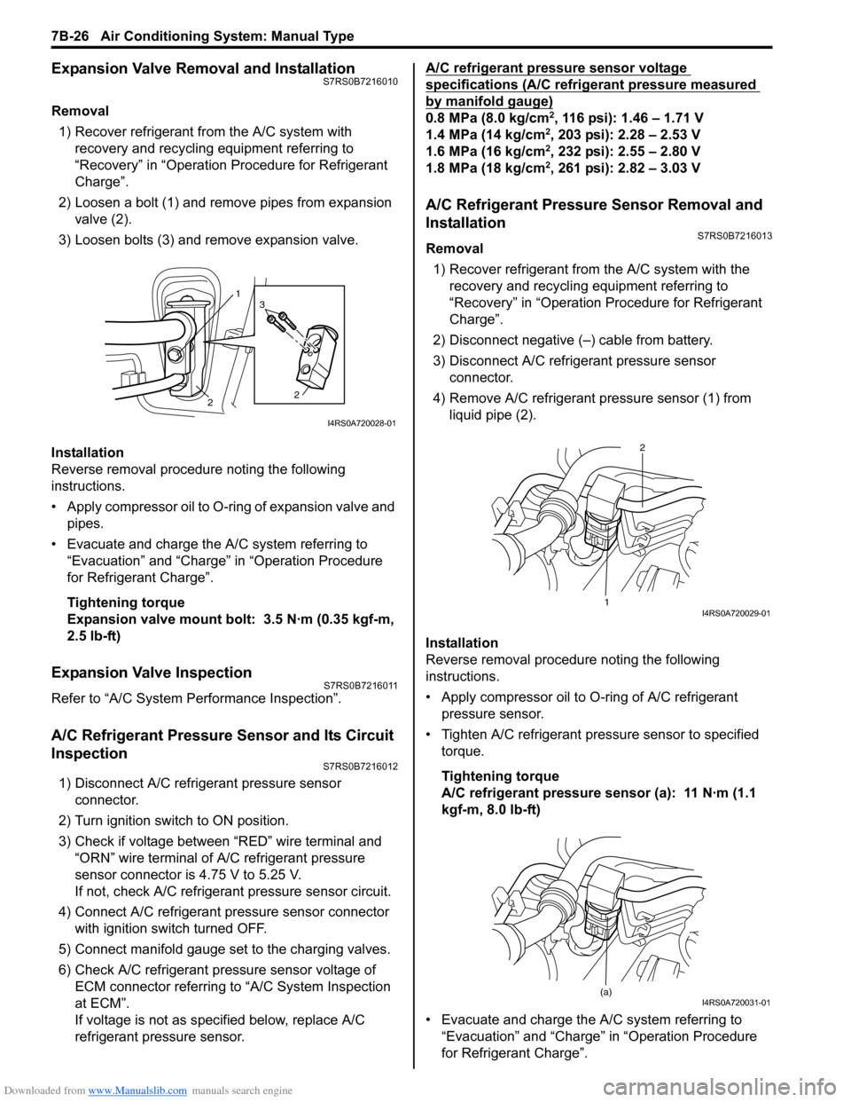
2) Loosen a bolt (1) and remove pipes from expansion valve (2).
3) Loosen bolts (3) and remove expansion valve.
Installation
Reverse removal procedure noting the following
instructions.
• Apply compressor oil to O-ring of expansion valve and pipes.
• Evacuate and charge the A/C system referring to “Evacuation” and “Charge” in “Operation Procedure
for Refrigerant Charge”.
Tightening torque
Expansion valve mount bolt: 3.5 N·m (0.35 kgf-m,
2.5 lb-ft)
Expansion Valve InspectionS7RS0B7216011
Refer to “A/C System Performance Inspection”.
A/C Refrigerant Pressure Sensor and Its Circuit
Inspection
S7RS0B7216012
1) Disconnect A/C refrigerant pressure sensor connector.
2) Turn ignition switch to ON position.
3) Check if voltage between “RED” wire terminal and “ORN” wire terminal of A/C refrigerant pressure
sensor connector is 4.75 V to 5.25 V.
If not, check A/C refrigerant pressure sensor circuit.
4) Connect A/C refrigerant pressure sensor connector with ignition switch turned OFF.
5) Connect manifold gauge set to the charging valves.
6) Check A/C refrigerant pressure sensor voltage of ECM connector referring to “A/C System Inspection
at ECM”.
If voltage is not as specified below, replace A/C
refrigerant pressure sensor. A/C refrigerant pressure sensor voltage
specifications (A/C refrigerant pressure measured
by manifold gauge)
0.8 MPa (8.0 kg/cm2, 116 psi): 1.46 – 1.71 V
1.4 MPa (14 kg/cm2, 203 psi): 2.28 – 2.53 V
1.6 MPa (16 kg/cm2, 232 psi): 2.55 – 2.80 V
1.8 MPa (18 kg/cm2, 261 psi): 2.82 – 3.03 V
A/C Refrigerant Pressure Sensor Removal and
Installation
S7RS0B7216013
Removal
1) Recover refrigerant from the A/C system with the recovery and recycling equipment referring to
“Recovery” in “Operation Procedure for Refrigerant
Charge”.
2) Disconnect negative (–) cable from battery.
3) Disconnect A/C refrigerant pressure sensor connector.
4) Remove A/C refrigerant pressure sensor (1) from liquid pipe (2).
Installation
Reverse removal procedure noting the following
instructions.
• Apply compressor oil to O-ring of A/C refrigerant
pressure sensor.
• Tighten A/C refrigerant pressure sensor to specified torque.
Tightening torque
A/C refrigerant pressure sensor (a): 11 N·m (1.1
kgf-m, 8.0 lb-ft)
• Evacuate and charge the A/C system referring to “Evacuation” and “Charge” in “Operation Procedure
for Refrigerant Charge”.
1
2 2
3
I4RS0A720028-01
1 2I4RS0A720029-01
(a)I4RS0A720031-01
Page 976 of 1496
Downloaded from www.Manualslib.com manuals search engine 7B-28 Air Conditioning System: Manual Type
Compressor Drive Belt Removal and
Installation
S7RS0B7216017
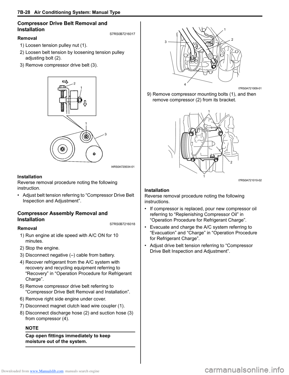
Removal1) Loosen tension pulley nut (1).
2) Loosen belt tension by loosening tension pulley adjusting bolt (2).
3) Remove compressor drive belt (3).
Installation
Reverse removal procedure noting the following
instruction.
• Adjust belt tension referring to “Compressor Drive Belt Inspection and Adjustment”.
Compressor Assembly Removal and
Installation
S7RS0B7216018
Removal
1) Run engine at idle speed with A/C ON for 10 minutes.
2) Stop the engine.
3) Disconnect negative (–) cable from battery.
4) Recover refrigerant fr om the A/C system with
recovery and recycling equipment referring to
“Recovery” in “Operation Procedure for Refrigerant
Charge”.
5) Remove compressor drive belt referring to “Compressor Drive Belt Re moval and Installation”.
6) Remove right side engine under cover.
7) Disconnect magnet clutch lead wire coupler (1).
8) Disconnect discharge hose (2) and suction hose (3) from compressor (4).
NOTE
Cap open fittings immediately to keep
moisture out of the system.
9) Remove compressor mounting bolts (1), and then remove compressor (2 ) from its bracket.
Installation
Reverse removal procedure noting the following
instructions.
• If compressor is replaced, pour new compressor oil referring to “Replenishi ng Compressor Oil” in
“Operation Procedure for Refrigerant Charge”.
• Evacuate and charge the A/C system referring to “Evacuation” and “Charge” in “Operation Procedure
for Refrigerant Charge”.
• Adjust drive belt tension referring to “Compressor Drive Belt Inspecti on and Adjustment”.
I4RS0A720034-01
3
4 2
1
I7RS0A721009-01
1
1 2
I7RS0A721010-02
Page 980 of 1496

Downloaded from www.Manualslib.com manuals search engine 7B-32 Air Conditioning System: Manual Type
Relief Valve Removal and InstallationS7RS0B7216030
Removal1) Recover refrigerant fr om the A/C system with
recovery and recycling equipment referring to
“Recovery” in “Operation Procedure for Refrigerant
Charge”.
2) Remove relief valve (1) from compressor (2). Installation
Reverse removal procedure nothing the following
instructions.
• Use new O-ring.
• Apply compressor oil to O-ring.
• Tighten relive valve to the specified torque.
Tightening torque
Relief valve (a): 8 N·m (0.8 kgf-m, 6.0 lb-ft)
• Evacuate and charge the A/C system referring to “Evacuation” and “Charge” in “Operation Procedure
for Refrigerant Charge”.
Specifications
Tightening Torque SpecificationsS7RS0B7217001
NOTE
The specified tightening torque is also described in the following.
“Compressor Assembly Components”
Reference:
For the tightening torque of fastener not specified in this section, refer to “Fasteners Information in Section 0A”.
12I4RS0A720048-01
(a)I4RS0A720049-01
Fastening part
Tightening torque
Note
N ⋅mkgf-mlb-ft
Receiver/dryer bolt 10 1.0 7.5 �)
Expansion valve mount bolt 3.5 0.35 2.5 �)
A/C refrigerant pressure sensor 11 1.1 8.0 �)
Armature plate bolt 15 1.5 11.0 �)
Relief valve 8 0.8 6.0 �)
Page 981 of 1496

Downloaded from www.Manualslib.com manuals search engine Air Conditioning System: Manual Type 7B-33
Special Tools and Equipment
Recommended Service MaterialS7RS0B7218001
NOTE
Required service material is also described in the following.
“Precautions on Servicing A/C System”
Special ToolS7RS0B7218002
Material SUZUKI recommended product or Specification Note
Compressor oil MATSUSHITADEN KI GU10 P/No.: 99000–99015–
00A �)
/ �)
Silicon sealant SUZUKI SILICON SEALANT KE-
347W (100g) P/No.: 99000–34220
�)
09900–06107 09990–86012
Snap ring pliers (opening
type) Gas leak detector
�) / �) / �) / �) This kit includes following
items. 1. Gas leak detector,
2. Instruction manual, 3.
Filter, 4. Sensor, 5. Dri-sell
battery (size D)�) / �)
09991–06310
Armature plate holder
�) / �)
1 2
3 4
5
Page 984 of 1496
Downloaded from www.Manualslib.com manuals search engine 7B-36 Air Conditioning System: Automatic Type
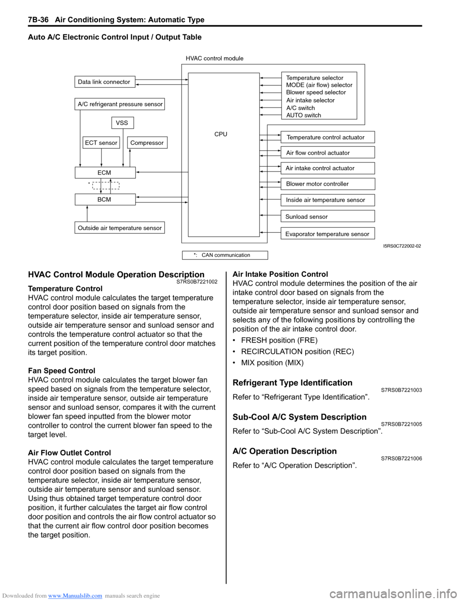
Auto A/C Electronic Control Input / Output Table
HVAC Control Module Operation DescriptionS7RS0B7221002
Temperature Control
HVAC control module calculates the target temperature
control door position based on signals from the
temperature selector, inside air temperature sensor,
outside air temperature sensor and sunload sensor and
controls the temperature control actuator so that the
current position of the temperature control door matches
its target position.
Fan Speed Control
HVAC control module calculates the target blower fan
speed based on signals from the temperature selector,
inside air temperature sensor, outside air temperature
sensor and sunload sensor, compares it with the current
blower fan speed inputted from the blower motor
controller to control the current blower fan speed to the
target level.
Air Flow Outlet Control
HVAC control module calculates the target temperature
control door position based on signals from the
temperature selector, inside air temperature sensor,
outside air temperature sensor and sunload sensor.
Using thus obtained target temperature control door
position, it further calculates the target air flow control
door position and controls the ai r flow control actuator so
that the current air flow c ontrol door position becomes
the target position. Air Intake Position Control
HVAC control module determines the position of the air
intake control door based on signals from the
temperature selector, inside air temperature sensor,
outside air temperature sensor and sunload sensor and
selects any of the following positions by controlling the
position of the air intake control door.
• FRESH position (FRE)
• RECIRCULATION position (REC)
• MIX position (MIX)
Refrigerant Type IdentificationS7RS0B7221003
Refer to “Refrigerant Type Identification”.
Sub-Cool A/C System DescriptionS7RS0B7221005
Refer to “Sub-Cool A/C System Description”.
A/C Operation DescriptionS7RS0B7221006
Refer to “A/C Operation Description”.
Sunload sensor
Outside air temperature sensor Evaporator temperature sensor
A/C refrigerant pressure sensor
Temperature selector
MODE (air flow) selector
Blower speed selector
Air intake selector
AUTO switch
A/C switch
Compressor
Blower motor controller
Temperature control actuator
Air flow control actuator
Air intake control actuator
BCM
ECM
Data link connector
HVAC control module
CPU
ECT sensor
Inside air temperature sensor
VSS
*
I5RS0C722002-02
*: CAN communication
Page 987 of 1496
Downloaded from www.Manualslib.com manuals search engine Air Conditioning System: Automatic Type 7B-39
Diagnostic Information and Procedures
A/C System Symptom DiagnosisS7RS0B7224001
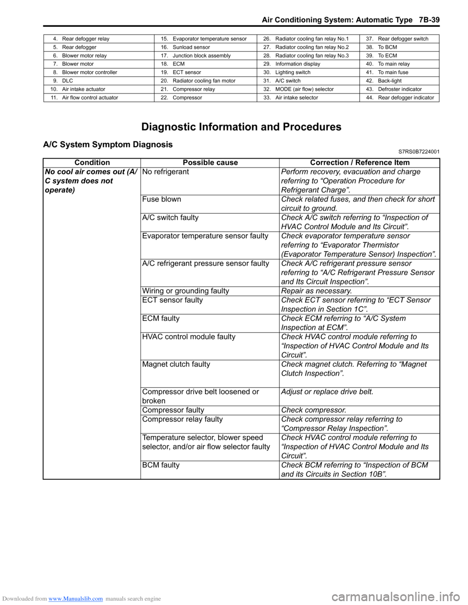
4. Rear defogger relay 15. Evaporator temperature sensor 26. Radiator cooling fan relay No.1 37. Rear defogger switch
5. Rear defogger 16. Sunload sensor 27. Radiator cooling fan relay No.2 38. To BCM
6. Blower motor relay 17. Junction block assembly 28. Radiator cooling fan relay No.3 39. To ECM
7. Blower motor 18. ECM 29. Information display 40. To main relay
8. Blower motor controller 19. ECT sensor 30. Lighting switch 41. To main fuse
9. DLC 20. Radiator cooling fan motor 31. A/C switch 42. Back-light
10. Air intake actuator 21. Compressor relay 32. MODE (air flow) selector 43. Defroster indicator 11. Air flow control actuator 22. Compressor 33. Air intake selector 44. Rear defogger indicator
Condition Possible cause Correction / Reference Item
No cool air comes out (A/
C system does not
operate) No refrigerant
Perform recovery, evacuation and charge
referring to “Operation Procedure for
Refrigerant Charge”.
Fuse blown Check related fuses, and then check for short
circuit to ground.
A/C switch faulty Check A/C switch referring to “Inspection of
HVAC Control Module and Its Circuit”.
Evaporator temperature sensor faulty Check evaporator temperature sensor
referring to “Evaporator Thermistor
(Evaporator Temperature Sensor) Inspection”.
A/C refrigerant pressure sensor faulty Check A/C refrigerant pressure sensor
referring to “A/C Refrigerant Pressure Sensor
and Its Circuit Inspection”.
Wiring or grounding faulty Repair as necessary.
ECT sensor faulty Check ECT sensor referring to “ECT Sensor
Inspection in Section 1C”.
ECM faulty Check ECM referring to “A/C System
Inspection at ECM”.
HVAC control module faulty Check HVAC control module referring to
“Inspection of HVAC Control Module and Its
Circuit”.
Magnet clutch faulty Check magnet clutch. Referring to “Magnet
Clutch Inspection”.
Compressor drive belt loosened or
broken Adjust or replace drive belt.
Compressor faulty Check compressor.
Compressor relay faulty Check compressor relay referring to
“Compressor Relay Inspection”.
Temperature selector, blower speed
selector, and/or air flow selector faulty Check HVAC control module referring to
“Inspection of HVAC Control Module and Its
Circuit”.
BCM faulty Check BCM referring to “Inspection of BCM
and its Circuits in Section 10B”.
Page 991 of 1496
Downloaded from www.Manualslib.com manuals search engine Air Conditioning System: Automatic Type 7B-43
Not Using SUZUKI Scan Tool
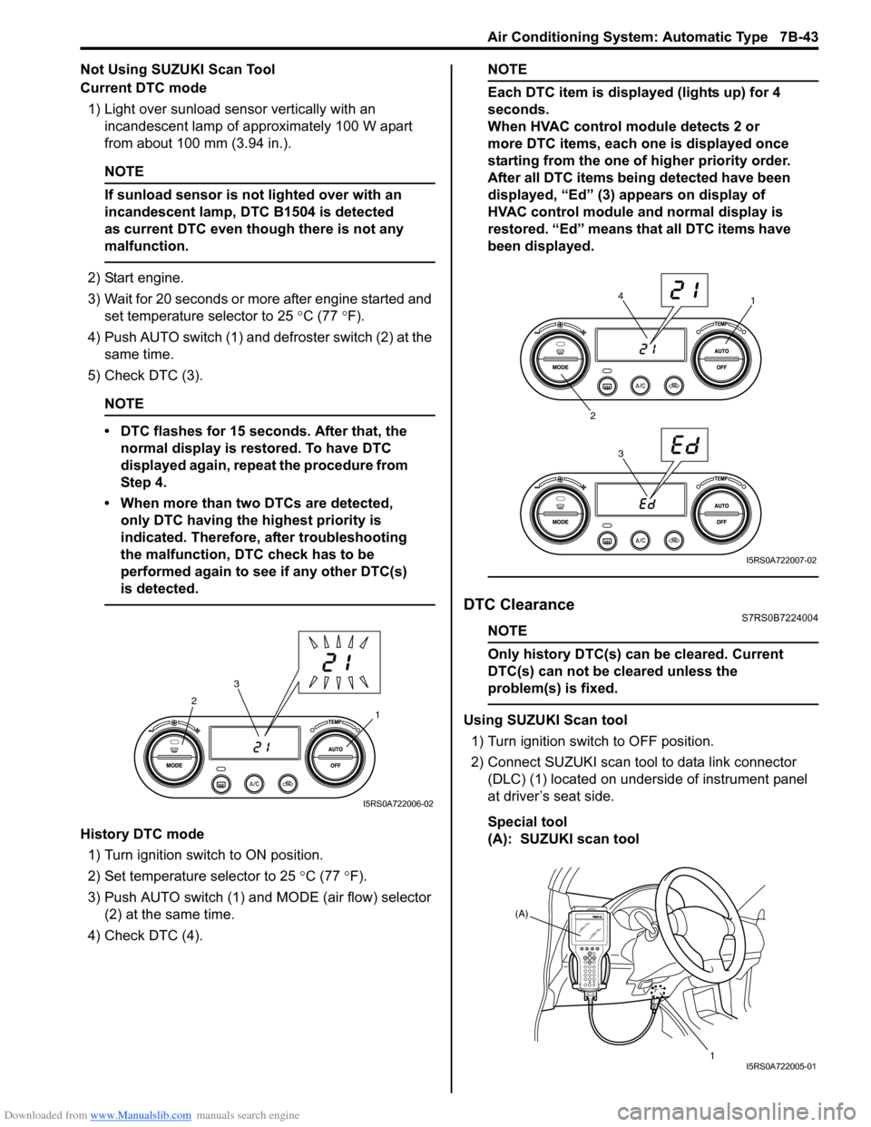
Current DTC mode1) Light over sunload sensor vertically with an incandescent lamp of approximately 100 W apart
from about 100 mm (3.94 in.).
NOTE
If sunload sensor is not lighted over with an
incandescent lamp, DTC B1504 is detected
as current DTC even though there is not any
malfunction.
2) Start engine.
3) Wait for 20 seconds or more after engine started and set temperature selector to 25 °C (77 °F).
4) Push AUTO switch (1) and defroster switch (2) at the same time.
5) Check DTC (3).
NOTE
• DTC flashes for 15 seconds. After that, the normal display is rest ored. To have DTC
displayed again, repeat the procedure from
Step 4.
• When more than two DTCs are detected, only DTC having the highest priority is
indicated. Therefore, after troubleshooting
the malfunction, DTC check has to be
performed again to see if any other DTC(s)
is detected.
History DTC mode
1) Turn ignition switch to ON position.
2) Set temperature selector to 25 °C (77 °F).
3) Push AUTO switch (1) and MODE (air flow) selector
(2) at the same time.
4) Check DTC (4).
NOTE
Each DTC item is displayed (lights up) for 4
seconds.
When HVAC control module detects 2 or
more DTC items, each one is displayed once
starting from the one of higher priority order.
After all DTC items being detected have been
displayed, “Ed” (3) appears on display of
HVAC control module and normal display is
restored. “Ed” means that all DTC items have
been displayed.
DTC ClearanceS7RS0B7224004
NOTE
Only history DTC(s) can be cleared. Current
DTC(s) can not be cleared unless the
problem(s) is fixed.
Using SUZUKI Scan tool
1) Turn ignition switch to OFF position.
2) Connect SUZUKI scan tool to data link connector (DLC) (1) located on underside of instrument panel
at driver’s seat side.
Special tool
(A): SUZUKI scan tool1
2
3
I5RS0A722006-02
1
2 34
I5RS0A722007-02
(A)
1
I5RS0A722005-01
Page 996 of 1496
Downloaded from www.Manualslib.com manuals search engine 7B-48 Air Conditioning System: Automatic Type
Description for Each Step
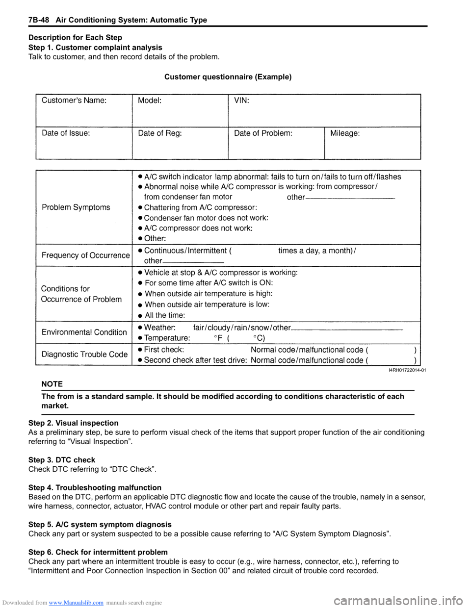
Step 1. Customer complaint analysis
Talk to customer, and then record details of the problem.
Customer questionnaire (Example)
NOTE
The from is a standard sample. It should be modified according to conditions characteristic of each
market.
Step 2. Visual inspection
As a preliminary step, be sure to perform visual check of th e items that support proper function of the air conditioning
referring to “Visual Inspection”.
Step 3. DTC check
Check DTC referring to “DTC Check”.
Step 4. Troubleshooting malfunction
Based on the DTC, perform an applicable DTC diagnostic flow and locate the cause of the trouble, namely in a sensor,
wire harness, connector, actuat or, HVAC control module or other part and repair faulty parts.
Step 5. A/C system symptom diagnosis
Check any part or system suspected to be a possible cause referring to “A/C System Symptom Diagnosis”.
Step 6. Check for intermittent problem
Check any part where an intermittent trouble is easy to oc cur (e.g., wire harness, connector, etc.), referring to
“Intermittent and Poor Connection Inspection in Sect ion 00” and related circuit of trouble cord recorded.
I4RH01722014-01