2006 SUZUKI SWIFT Nut
[x] Cancel search: NutPage 1314 of 1496
Downloaded from www.Manualslib.com manuals search engine 9C-19 Instrumentation / Driver Info. / Horn:
Installation
Reverse removal procedure noting the following.
• When installing each part, be careful not to catch any
cable or wiring harness.
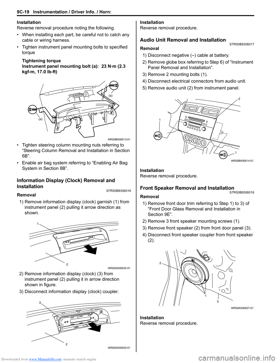
• Tighten instrument panel mounting bolts to specified
torque
Tightening torque
Instrument panel mounting bolt (a): 23 N·m (2.3
kgf-m, 17.0 lb-ft)
• Tighten steering column mounting nuts referring to “Steering Column Removal an d Installation in Section
6B”.
• Enable air bag system referring to “Enabling Air Bag System in Section 8B”.
Information Display (Clock) Removal and
Installation
S7RS0B9306016
Removal
1) Remove information display (clock) garnish (1) from instrument panel (2) pulling it arrow direction as
shown.
2) Remove information di splay (clock) (3) from
instrument panel (2) pulli ng it in arrow direction
shown in figure.
3) Disconnect information display (clock) coupler. Installation
Reverse removal procedure.
Audio Unit Removal and InstallationS7RS0B9306017
Removal
1) Disconnect negative (–) cable at battery.
2) Remove globe box referring to Step 6) of “Instrument Panel Removal and Installation”.
3) Remove 2 mounting bolts (1).
4) Disconnect electrical connectors from audio unit.
5) Remove audio unit (2) from instrument panel.
Installation
Reverse removal procedure.
Front Speaker Removal and InstallationS7RS0B9306018
Removal 1) Remove front door trim refe rring to Step 1) to 3) of
“Front Door Glass Remo val and Installation in
Section 9E”.
2) Remove 3 front speaker mounting screws (1).
3) Remove front speaker (2) from front door panel (3).
4) Disconnect front speaker coupler from front speaker (2).
Installation
Reverse removal procedure.
(a) (a)
I4RS0B930013-01
1
2I4RS0A930032-01
3
2I4RS0A930025-01
2
1
1
I4RS0B930014-01
1
2
3
I4RS0A930027-01
Page 1316 of 1496
Downloaded from www.Manualslib.com manuals search engine 9C-21 Instrumentation / Driver Info. / Horn:
Antenna Amplifier Removal and InstallationS7RS0B9306023
NOTE
Antenna amplifier incorporated with antenna
base.
Removal1) Remove head lining referring to “Head Lining Removal and Installa tion in Section 9H”.
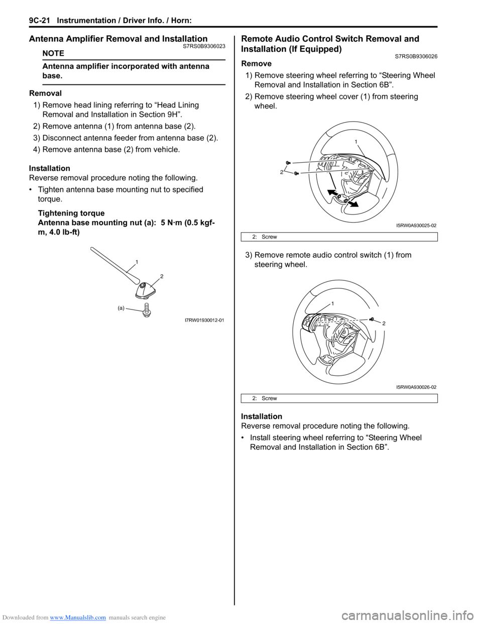
2) Remove antenna (1) from antenna base (2).
3) Disconnect antenna feeder from antenna base (2).
4) Remove antenna base (2) from vehicle.
Installation
Reverse removal procedure noting the following.
• Tighten antenna base mounting nut to specified torque.
Tightening torque
Antenna base mounting nut (a): 5 N·m (0.5 kgf-
m, 4.0 lb-ft)
Remote Audio Control Switch Removal and
Installation (If Equipped)
S7RS0B9306026
Remove
1) Remove steering wheel re ferring to “Steering Wheel
Removal and Installati on in Section 6B”.
2) Remove steering wheel cover (1) from steering wheel.
3) Remove remote audio control switch (1) from steering wheel.
Installation
Reverse removal procedure noting the following.
• Install steering wheel referring to “Steering Wheel Removal and Installati on in Section 6B”.
(a)1
2
I7RW01930012-01
2: Screw
2: Screw
2
1
I5RW0A930025-02
1
2
I5RW0A930026-02
Page 1317 of 1496
Downloaded from www.Manualslib.com manuals search engine Instrumentation / Driver Info. / Horn: 9C-22
Remote Audio Control Switch Inspection (If
Equipped)
S7RS0B9306024
1) Remove driver air bag (inflator) module referring to
“Driver Air Bag (Inflator) Module Removal and
Installation in Section 8B”.
2) Disconnect remote audio control switch connector
from contact coil.
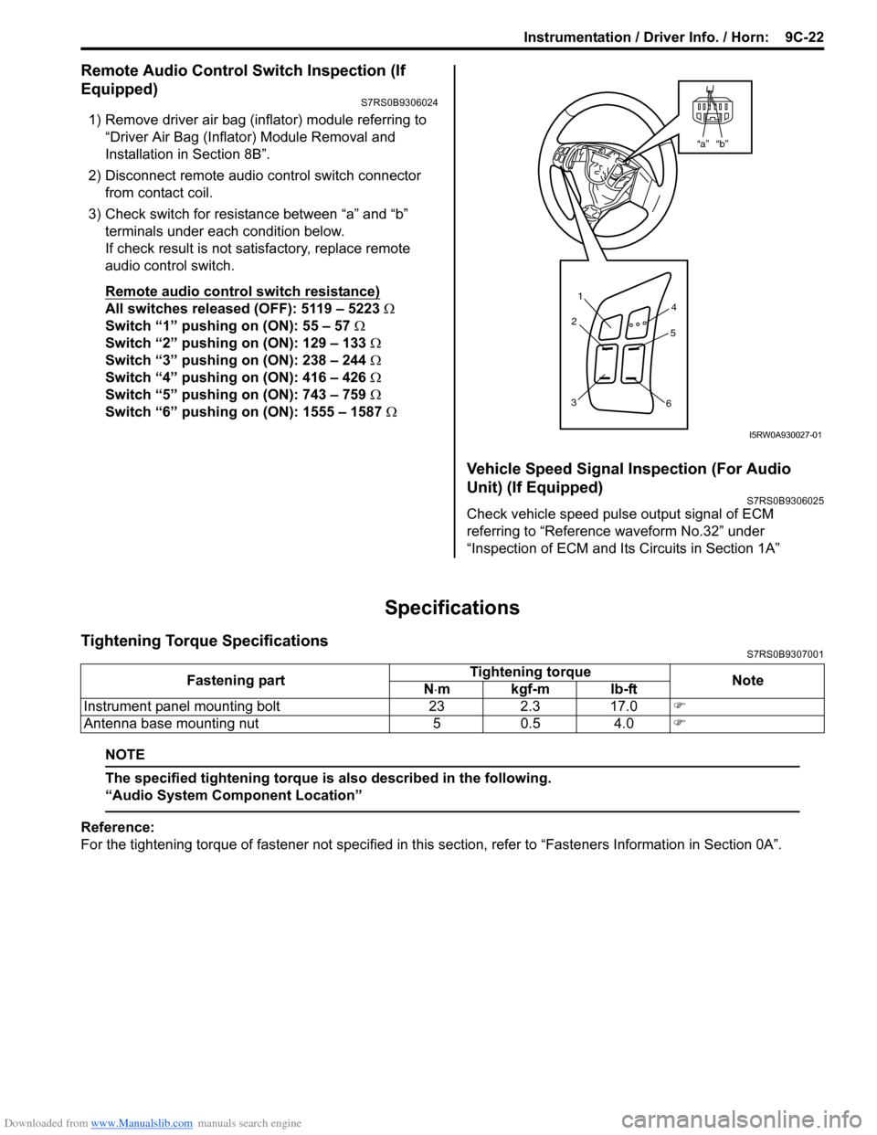
3) Check switch for resistance between “a” and “b” terminals under each condition below.
If check result is not satisfactory, replace remote
audio control switch.
Remote audio control switch resistance)
All switches released (OFF): 5119 – 5223 Ω
Switch “1” pushing on (ON): 55 – 57 Ω
Switch “2” pushing on (ON): 129 – 133 Ω
Switch “3” pushing on (ON): 238 – 244 Ω
Switch “4” pushing on (ON): 416 – 426 Ω
Switch “5” pushing on (ON): 743 – 759 Ω
Switch “6” pushing on (ON): 1555 – 1587 Ω
Vehicle Speed Signal Inspection (For Audio
Unit) (If Equipped)
S7RS0B9306025
Check vehicle speed pulse output signal of ECM
referring to “Reference waveform No.32” under
“Inspection of ECM and Its Circuits in Section 1A”
Specifications
Tightening Torque SpecificationsS7RS0B9307001
NOTE
The specified tightening torque is also described in the following.
“Audio System Component Location”
Reference:
For the tightening torque of fastener not specified in this section, refer to “Fasteners Information in Section 0A”.
“b”“a”
1
2
3 4
5
6
I5RW0A930027-01
Fastening part Tightening torque
Note
N ⋅mkgf-mlb-ft
Instrument panel mounting bolt 23 2.3 17.0 �)
Antenna base mounting nut 5 0.5 4.0 �)
Page 1321 of 1496
Downloaded from www.Manualslib.com manuals search engine Wipers / Washers: 9D-4
Windshield Wiper Removal and InstallationS7RS0B9406004
Removal1) Disconnect negative (–) cable at battery.
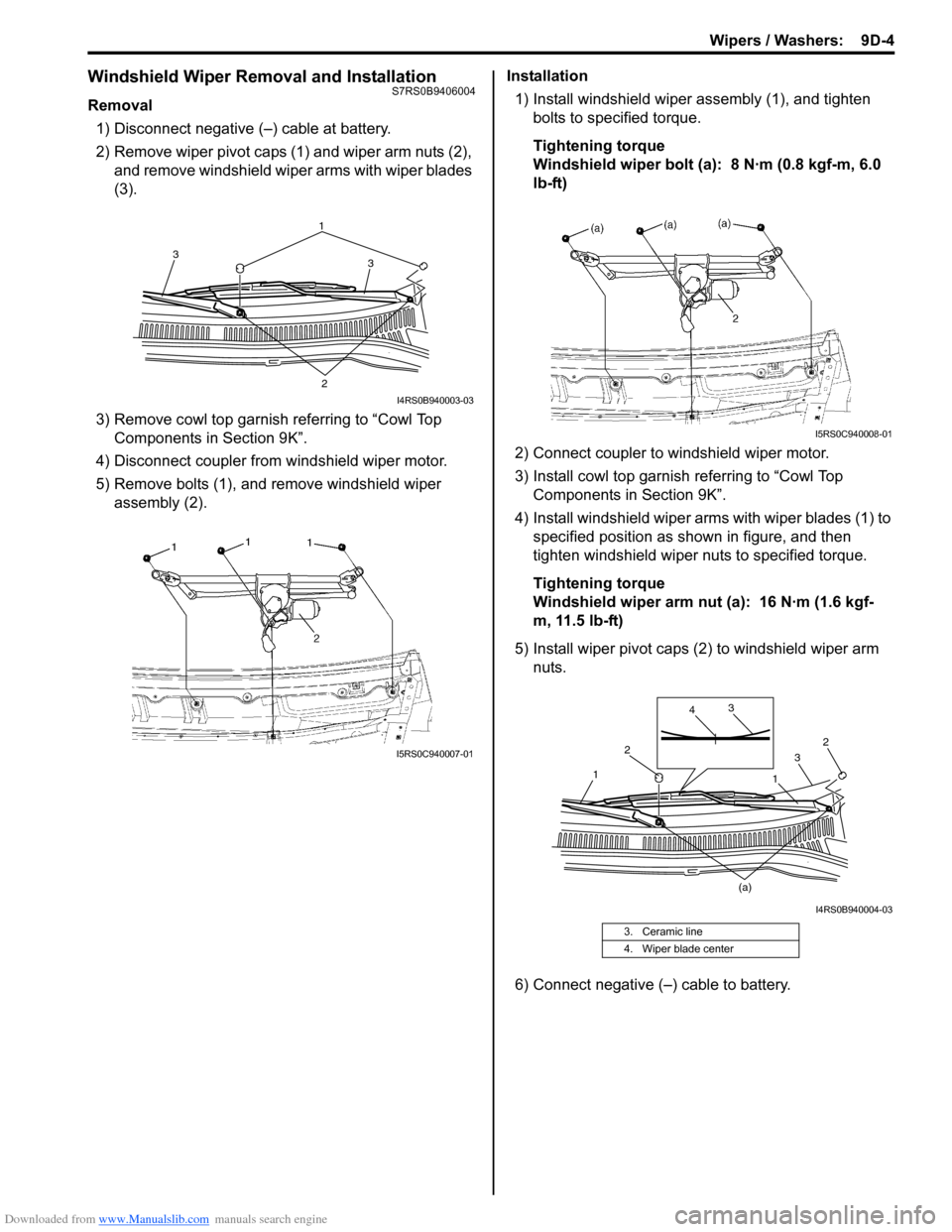
2) Remove wiper pivot caps (1) and wiper arm nuts (2), and remove windshield wiper arms with wiper blades
(3).
3) Remove cowl top garnish referring to “Cowl Top Components in Section 9K”.
4) Disconnect coupler from windshield wiper motor.
5) Remove bolts (1), and remove windshield wiper assembly (2). Installation
1) Install windshield wiper assembly (1), and tighten bolts to specified torque.
Tightening torque
Windshield wiper bolt (a): 8 N·m (0.8 kgf-m, 6.0
lb-ft)
2) Connect coupler to windshield wiper motor.
3) Install cowl top garnish referring to “Cowl Top
Components in Section 9K”.
4) Install windshield wiper arms with wiper blades (1) to specified position as shown in figure, and then
tighten windshield wiper nuts to specified torque.
Tightening torque
Windshield wiper arm nut (a): 16 N·m (1.6 kgf-
m, 11.5 lb-ft)
5) Install wiper pivot caps (2 ) to windshield wiper arm
nuts.
6) Connect negative (–) cable to battery.
1 3
3
2
I4RS0B940003-03
I5RS0C940007-01
3. Ceramic line
4. Wiper blade center
I5RS0C940008-01
2
2 3
3
4
1
1
(a)
I4RS0B940004-03
Page 1323 of 1496
Downloaded from www.Manualslib.com manuals search engine Wipers / Washers: 9D-6
Rear Wiper Removal and InstallationS7RS0B9406006
Removal1) Disconnect negative (–) cable at battery.
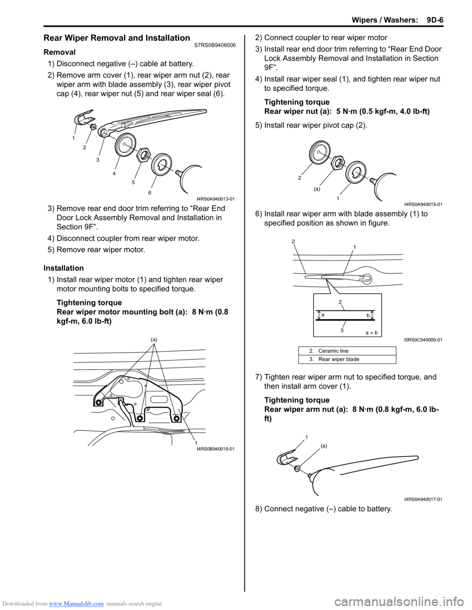
2) Remove arm cover (1), rear wiper arm nut (2), rear wiper arm with blade assembly (3), rear wiper pivot
cap (4), rear wiper nut (5) and rear wiper seal (6).
3) Remove rear end door trim referring to “Rear End Door Lock Assembly Remo val and Installation in
Section 9F”.
4) Disconnect coupler from rear wiper motor.
5) Remove rear wiper motor.
Installation 1) Install rear wiper motor (1) and tighten rear wiper motor mounting bolts to specified torque.
Tightening torque
Rear wiper motor mounting bolt (a): 8 N·m (0.8
kgf-m, 6.0 lb-ft) 2) Connect coupler to rear wiper motor
3) Install rear end door trim referring to “Rear End Door
Lock Assembly Removal and Installation in Section
9F”.
4) Install rear wiper seal (1), and tighten rear wiper nut to specified torque.
Tightening torque
Rear wiper nut (a): 5 N·m (0.5 kgf-m, 4.0 lb-ft)
5) Install rear wiper pivot cap (2).
6) Install rear wiper arm with blade assembly (1) to specified position as shown in figure.
7) Tighten rear wiper arm nut to specified torque, and then install arm cover (1).
Tightening torque
Rear wiper arm nut (a): 8 N·m (0.8 kgf-m, 6.0 lb-
ft)
8) Connect negative (–) cable to battery.
1 2
3
4 5
6
I4RS0A940013-01
1
(a)I4RS0B940018-01
2. Ceramic line
3. Rear wiper blade
2
1
(a)
I4RS0A940015-01
1
2
3
2a = b
a
bI5RS0C940009-01
1
(a)
I4RS0A940017-01
Page 1327 of 1496
Downloaded from www.Manualslib.com manuals search engine Wipers / Washers: 9D-10
Rear Wiper Relay Removal and InstallationS7RS0B9406012
Removal1) Disconnect negative (–) cable at battery.
2) Remove junction block assembly referring to “BCM (Included in Junction Block Assembly) Removal and
Installation in Section 10B”.
3) Remove rear wiper relay.
Installation
Reverse removal procedure for installation.
Rear Wiper Relay InspectionS7RS0B9406013
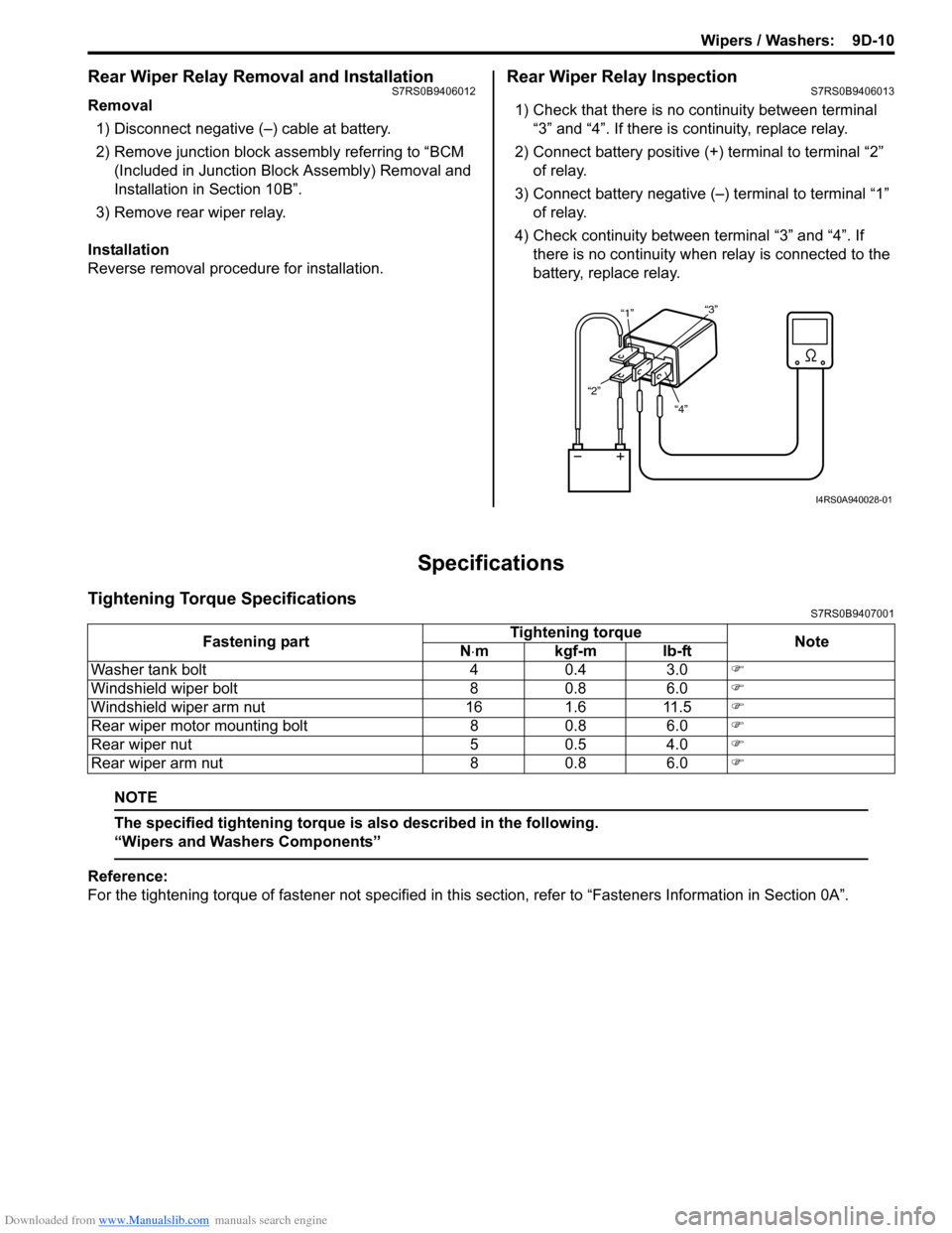
1) Check that there is no continuity between terminal “3” and “4”. If there is continuity, replace relay.
2) Connect battery positive (+ ) terminal to terminal “2”
of relay.
3) Connect battery negative (–) terminal to terminal “1” of relay.
4) Check continuity between terminal “3” and “4”. If
there is no continuity when relay is connected to the
battery, replace relay.
Specifications
Tightening Torque SpecificationsS7RS0B9407001
NOTE
The specified tightening torque is also described in the following.
“Wipers and Washers Components”
Reference:
For the tightening torque of fastener not specified in this section, refer to “Fasteners Information in Section 0A”.
“4”
“2” “1”
“3”
I4RS0A940028-01
Fastening part Tightening torque
Note
N ⋅mkgf-mlb-ft
Washer tank bolt 4 0.4 3.0 �)
Windshield wiper bolt 8 0.8 6.0 �)
Windshield wiper arm nut 16 1.6 11.5 �)
Rear wiper motor mounting bolt 8 0.8 6.0 �)
Rear wiper nut 5 0.5 4.0 �)
Rear wiper arm nut 8 0.8 6.0 �)
Page 1332 of 1496
Downloaded from www.Manualslib.com manuals search engine 9E-5 Glass / Windows / Mirrors:
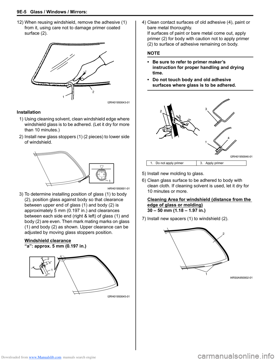
12) When reusing windshield, remove the adhesive (1) from it, using care not to damage primer coated
surface (2).
Installation 1) Using cleaning solvent, clean windshield edge where windshield glass is to be adhered. (Let it dry for more
than 10 minutes.)
2) Install new glass stoppers (1) (2 pieces) to lower side of windshield.
3) To determine installing position of glass (1) to body (2), position glass against body so that clearance
between upper end of glass (1) and body (2) is
approximately 5 mm (0.197 in.) and clearances
between each side end (right & left) of glass (1) and
body (2) are even. Then mark mating marks on glass
(1) and body (2) as shown. Upper clearance can be
adjusted by moving glass stoppers position.
Windshield clearance
“a”: approx. 5 mm (0.197 in.) 4) Clean contact surfaces of old adhesive (4), paint or
bare metal thoroughly.
If surfaces of paint or ba re metal come out, apply
primer (2) for body with caution not to apply primer
(2) to surface of adhesive remaining on body.
NOTE
• Be sure to refer to primer maker’s instruction for proper handling and drying
time.
• Do not touch body and old adhesive surfaces where glass is to be adhered.
5) Install new molding to glass.
6) Clean glass surface to be adhered to body with clean cloth. If cleaning solvent is used, let it dry for
10 minutes or more.
Cleaning Area for windshie ld (distance from the
edge of glass or molding)
30 – 50 mm (1.18 – 1.97 in.)
7) Install new spacers (1) to windshield (2).
I2RH01950043-01
1
I4RH01950001-01
2
1“a”
I2RH01950045-01
1. Do not apply primer 3. Apply primer
I2RH01950046-01
2
1I4RS0A950002-01
Page 1342 of 1496
Downloaded from www.Manualslib.com manuals search engine 9E-15 Glass / Windows / Mirrors:
Rear End Door Window Defogger Wire
Inspection
S7RS0B9506014
NOTE
• When cleaning rear end door window glass, use a dry cloth to wipe it along heat
wire (1) direction.
• When cleaning glass, do not use detergent or abrasive-containing glass cleaner.
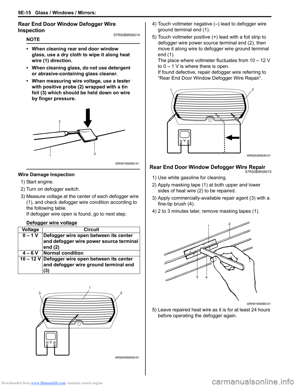
• When measuring wire voltage, use a tester with positive probe (2) wrapped with a tin
foil (3) which should be held down on wire
by finger pressure.
Wire Damage Inspection
1) Start engine.
2) Turn on defogger switch.
3) Measure voltage at the center of each defogger wire (1), and check defogger wire condition according to
the following table.
If defogger wire open is found, go to next step.
Defogger wire voltage
4) Touch voltmeter negative (–) lead to defogger wire ground terminal end (1).
5) Touch voltmeter positive (+) lead with a foil strip to defogger wire power source terminal end (2), then
move it along wire to defogger wire ground terminal
end (1).
The place where voltmeter fluctuates from 10 – 12 V
to 0 – 1 V is where there is open.
If found defective, repair defogger wire referring to
“Rear End Door Window Defogger Wire Repair”.
Rear End Door Window Defogger Wire RepairS7RS0B9506015
1) Use white gasoline for cleaning.
2) Apply masking tape (1) at both upper and lower sides of heat wire (2) to be repaired.
3) Apply commercially-available repair agent (3) with a fine-tip brush (4).
4) 2 to 3 minutes later, remove masking tapes (1).
5) Leave repaired heat wire as it is for at least 24 hours before operating the defogger again.
Voltage Circuit
0 – 1 V Defogger wire open between its center and defogger wire power source terminal
end (2)
4 – 6 V Normal condition
10 – 12 V Defogger wire open between its center and defogger wire ground terminal end
(3)
I2RH01950002-01
2
1
3
I4RS0A950029-01
21
I4RS0A950030-01
I2RH01950005-01