2006 SUZUKI SWIFT Nut
[x] Cancel search: NutPage 966 of 1496
Downloaded from www.Manualslib.com manuals search engine 7B-18 Air Conditioning System: Manual Type
When replacing other parts
Replenish the following amount of oil to compressor.
Amount of compressor oil to be replenished
Evaporator: 25 cm3 (25 ml, 0.85 US. oz, 0.88 Imp. oz)
Condenser: 15 cm3 (15 ml, 0.51 US. oz, 0.53 Imp. oz)
Receiver/dryer: 10 cm3 (10 ml, 0.34 US. oz, 0.35 lmp.
oz)
Hoses: 10 cm
3 (10 ml, 0.34 US. oz, 0.35 Imp. oz) each
Pipes: 10 cm3 (10 ml, 0.34 US. oz, 0.35 Imp. oz) each
Evacuation
CAUTION!
Do not evacuate before recovering
refrigerant in A/C system.
NOTE
Once air conditioning system circuit is
opened (exposed) to atmospheric air, system
must be evacuated by using a vacuum pump.
The A/C system should be attached with a
manifold gauge set, and should be evacuated
for approximately 15 minutes.
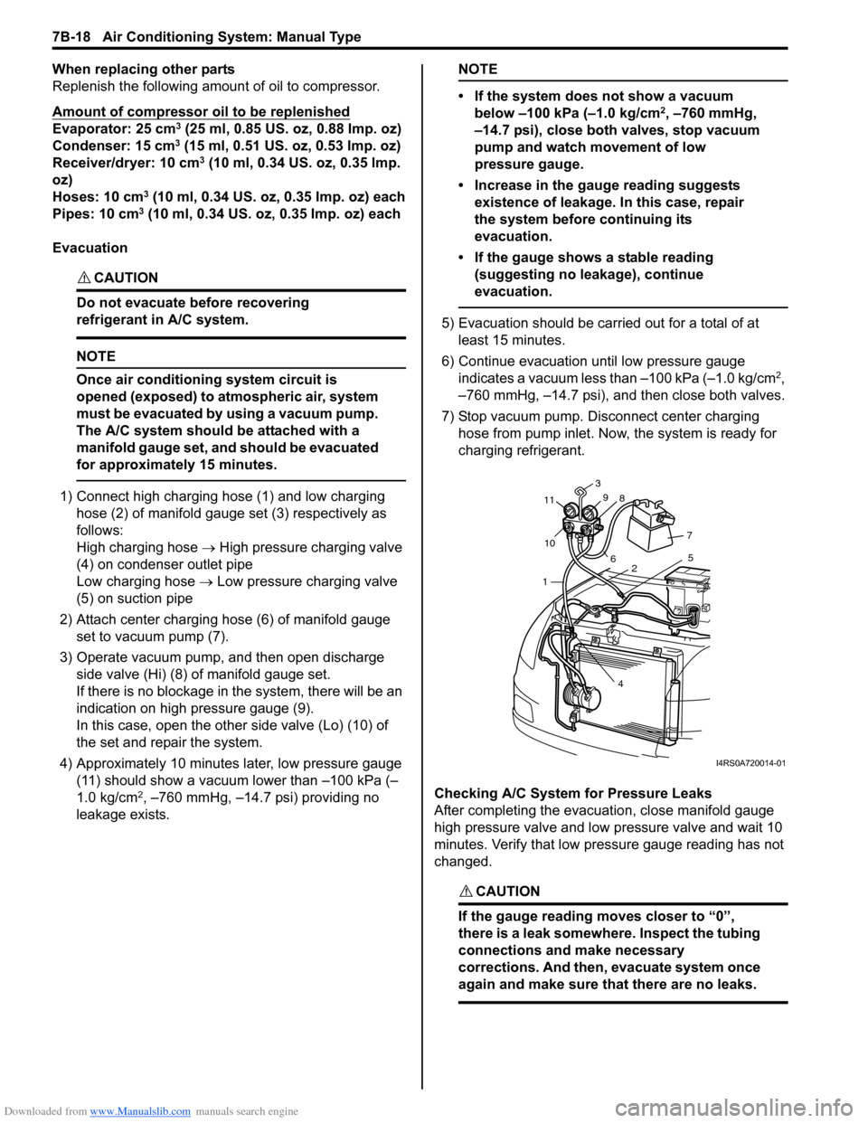
1) Connect high charging hose (1) and low charging hose (2) of manifold gauge set (3) respectively as
follows:
High charging hose → High pressure charging valve
(4) on condenser outlet pipe
Low charging hose → Low pressure charging valve
(5) on suction pipe
2) Attach center charging hose (6) of manifold gauge set to vacuum pump (7).
3) Operate vacuum pump, and then open discharge
side valve (Hi) (8) of manifold gauge set.
If there is no blockage in the system, there will be an
indication on high pressure gauge (9).
In this case, open the other side valve (Lo) (10) of
the set and repair the system.
4) Approximately 10 minutes later, low pressure gauge (11) should show a vacuum lower than –100 kPa (–
1.0 kg/cm
2, –760 mmHg, –14.7 psi) providing no
leakage exists.
NOTE
• If the system does not show a vacuum below –100 kPa (–1.0 kg/cm
2, –760 mmHg,
–14.7 psi), close both valves, stop vacuum
pump and watch movement of low
pressure gauge.
• Increase in the gauge reading suggests existence of leakage. In this case, repair
the system before continuing its
evacuation.
• If the gauge shows a stable reading (suggesting no leakage), continue
evacuation.
5) Evacuation should be carried out for a total of at least 15 minutes.
6) Continue evacuation until low pressure gauge indicates a vacuum less than –100 kPa (–1.0 kg/cm
2,
–760 mmHg, –14.7 psi), and then close both valves.
7) Stop vacuum pump. Disconnect center charging hose from pump inlet. No w, the system is ready for
charging refrigerant.
Checking A/C System for Pressure Leaks
After completing the evacuation, close manifold gauge
high pressure valve and low pressure valve and wait 10
minutes. Verify that low pressure gauge reading has not
changed.
CAUTION!
If the gauge reading moves closer to “0”,
there is a leak somewhere. Inspect the tubing
connections and make necessary
corrections. And then, evacuate system once
again and make sure that there are no leaks.
7 5
2
4
1
10
11
3
9 8
6
I4RS0A720014-01
Page 968 of 1496
Downloaded from www.Manualslib.com manuals search engine 7B-20 Air Conditioning System: Manual Type
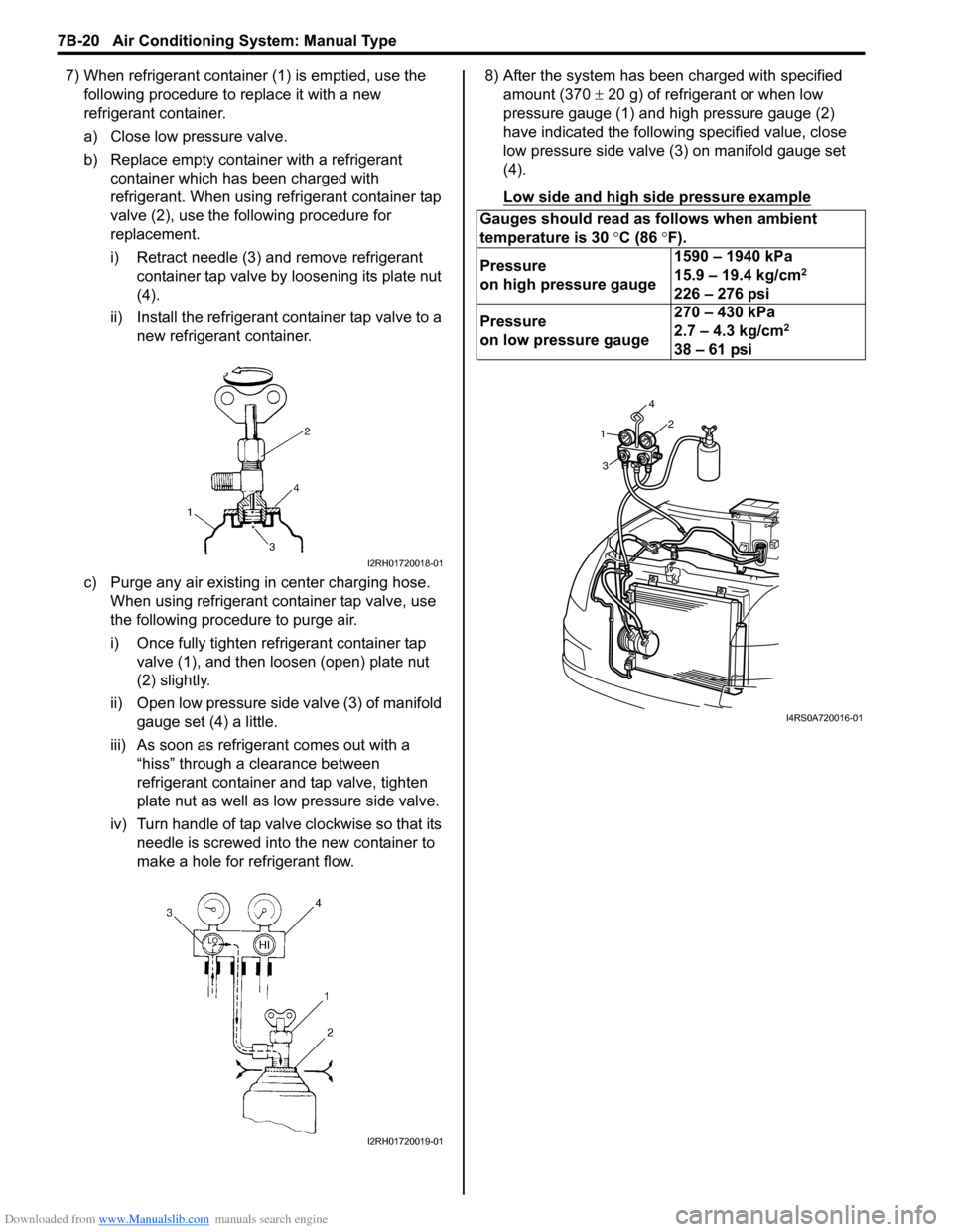
7) When refrigerant container (1) is emptied, use the following procedure to replace it with a new
refrigerant container.
a) Close low pressure valve.
b) Replace empty container with a refrigerant container which has been charged with
refrigerant. When using refrigerant container tap
valve (2), use the following procedure for
replacement.
i) Retract needle (3) and remove refrigerant container tap valve by loosening its plate nut
(4).
ii) Install the refrigerant container tap valve to a new refrigerant container.
c) Purge any air existing in center charging hose. When using refrigerant container tap valve, use
the following procedure to purge air.
i) Once fully tighten refrigerant container tap valve (1), and then loosen (open) plate nut
(2) slightly.
ii) Open low pressure side valve (3) of manifold
gauge set (4) a little.
iii) As soon as refrigerant comes out with a “hiss” through a clearance between
refrigerant container and tap valve, tighten
plate nut as well as low pressure side valve.
iv) Turn handle of tap valve clockwise so that its needle is screwed into the new container to
make a hole for refrigerant flow. 8) After the system has been charged with specified
amount (370 ± 20 g) of refrigerant or when low
pressure gauge (1) and high pressure gauge (2)
have indicated the following specified value, close
low pressure side valve (3) on manifold gauge set
(4).
Low side and high side pressure example
I2RH01720018-01
I2RH01720019-01
Gauges should read as follows when ambient
temperature is 30 °C (86 °F).
Pressure
on high pressure gauge 1590 – 1940 kPa
15.9 – 19.4 kg/cm
2
226 – 276 psi
Pressure
on low pressure gauge 270 – 430 kPa
2.7 – 4.3 kg/cm
2
38 – 61 psi
1
3 42
I4RS0A720016-01
Page 972 of 1496

Downloaded from www.Manualslib.com manuals search engine 7B-24 Air Conditioning System: Manual Type
HVAC Unit Removal and InstallationS7RS0B7216006
Removal1) Disconnect negative (–) cable from battery.
2) Disable air bag system referring to “Disabling Air Bag System in Section 8B”.
3) Recover refrigerant from A/C system with recovery and recycling equipment referring to “Recovery” in
“Operation Procedure for Refrigerant Charge”.
4) Remove cowl top panel referring to “Cowl Top Components in Section 9K”.
5) Drain engine coolant, and then disconnect heater hoses (1) from HVAC unit (2).
6) Remove instrument panel from vehicle body referring to “Audio Unit Re moval and Installation in
Section 9C”.
7) Loosen suction hose and liquid pipe bolt (4).
8) Remove nuts (3).
9) Remove HVAC unit from vehicle body. Installation
Reverse removal procedure noting the following
instructions.
• Replenish specified amount of compressor oil to
compressor suction side referring to “Replenishing
Compressor Oil” in “Operation Procedure for
Refrigerant Charge”.
• Install the padding (1) to the installation hole uniformly.
• Evacuate and charge the A/C system referring to “Evacuation” and “Charge” in “Operation Procedure
for Refrigerant Charge”.
• Adjust control cables referr ing to “HVAC Control Unit
Removal and Installati on in Section 7A”.
• Enable air bag system referring to “Enabling Air Bag System in Section 8B”.
Evaporator InspectionS7RS0B7216007
Check the followings.
• Clog of A/C evaporator fins.If any clogs are found, A/C evaporator fins should be
washed with water, and then should be dried with
compressed air.
• A/C evaporator fins for leakage and breakage. If any defects are found, repair or replace A/C
evaporator.
• A/C evaporator fittings for leakage. If any defects are found, repair or replace A/C
evaporator.
2. Blower upper case 8. Temperature control door assembly 14. Temperature control lever 20. Packing
3. Air intake control actuator 9. Blower motor resistor 15. Airflow control lever21. Filter cover (if equipped)
4. HVAC Air filter (if equipped) 10. Blower lower case 16. Evaporator22. Drain hose
5. Heater unit upper case 11. Blower motor 17. O-ring23. Cable lock clamp
6. Foot duct 12. Heater unit lower case 18. Expansion valve: Do not reuse.
3
2
3
3
1
4
I4RS0B720009-01
1
I4RS0B720010-01
Page 975 of 1496
Downloaded from www.Manualslib.com manuals search engine Air Conditioning System: Manual Type 7B-27
A/C Switch InspectionS7RS0B7216014
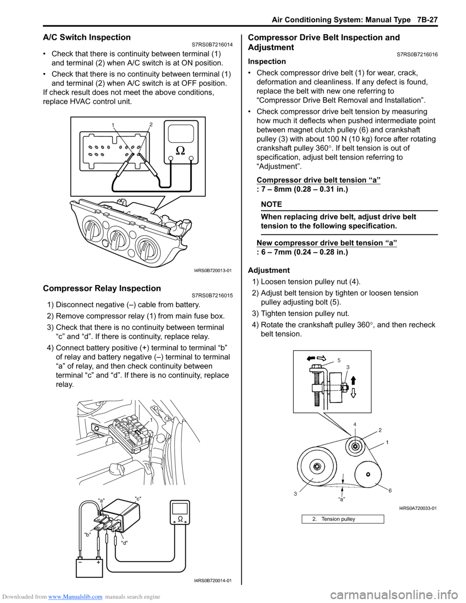
• Check that there is continuity between terminal (1) and terminal (2) when A/C s witch is at ON position.
• Check that there is no continuity between terminal (1) and terminal (2) when A/C s witch is at OFF position.
If check result does not meet the above conditions,
replace HVAC control unit.
Compressor Relay InspectionS7RS0B7216015
1) Disconnect negative (–) cable from battery.
2) Remove compressor relay (1) from main fuse box.
3) Check that there is no continuity between terminal “c” and “d”. If there is continuity, replace relay.
4) Connect battery positive (+ ) terminal to terminal “b”
of relay and battery negative (–) terminal to terminal
“a” of relay, and then check continuity between
terminal “c” and “d”. If there is no continuity, replace
relay.
Compressor Drive Belt Inspection and
Adjustment
S7RS0B7216016
Inspection
• Check compressor drive belt (1) for wear, crack, deformation and cleanliness. If any defect is found,
replace the belt with new one referring to
“Compressor Drive Belt Re moval and Installation”.
• Check compressor drive belt tension by measuring how much it deflects when pushed intermediate point
between magnet clutch pulley (6) and crankshaft
pulley (3) with about 100 N (10 kg) force after rotating
crankshaft pulley 360 °. If belt tension is out of
specification, adjust belt tension referring to
“Adjustment”.
Compressor drive belt tension
“a”
: 7 – 8mm (0.28 – 0.31 in.)
NOTE
When replacing drive belt, adjust drive belt
tension to the following specification.
New compressor dr ive belt tension “a”
: 6 – 7mm (0.24 – 0.28 in.)
Adjustment 1) Loosen tension pulley nut (4).
2) Adjust belt tension by ti ghten or loosen tension
pulley adjusting bolt (5).
3) Tighten tension pulley nut.
4) Rotate the crankshaft pulley 360 °, and then recheck
belt tension.
1 2
I4RS0B720013-01
"d"
"b" "a"
"c"
1
I4RS0B720014-01
2. Tension pulley
I4RS0A720033-01
Page 976 of 1496
Downloaded from www.Manualslib.com manuals search engine 7B-28 Air Conditioning System: Manual Type
Compressor Drive Belt Removal and
Installation
S7RS0B7216017
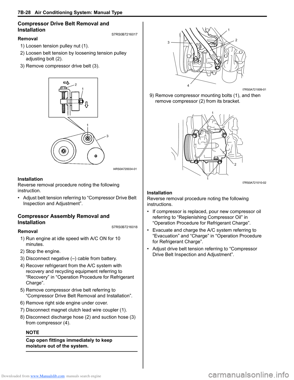
Removal1) Loosen tension pulley nut (1).
2) Loosen belt tension by loosening tension pulley adjusting bolt (2).
3) Remove compressor drive belt (3).
Installation
Reverse removal procedure noting the following
instruction.
• Adjust belt tension referring to “Compressor Drive Belt Inspection and Adjustment”.
Compressor Assembly Removal and
Installation
S7RS0B7216018
Removal
1) Run engine at idle speed with A/C ON for 10 minutes.
2) Stop the engine.
3) Disconnect negative (–) cable from battery.
4) Recover refrigerant fr om the A/C system with
recovery and recycling equipment referring to
“Recovery” in “Operation Procedure for Refrigerant
Charge”.
5) Remove compressor drive belt referring to “Compressor Drive Belt Re moval and Installation”.
6) Remove right side engine under cover.
7) Disconnect magnet clutch lead wire coupler (1).
8) Disconnect discharge hose (2) and suction hose (3) from compressor (4).
NOTE
Cap open fittings immediately to keep
moisture out of the system.
9) Remove compressor mounting bolts (1), and then remove compressor (2 ) from its bracket.
Installation
Reverse removal procedure noting the following
instructions.
• If compressor is replaced, pour new compressor oil referring to “Replenishi ng Compressor Oil” in
“Operation Procedure for Refrigerant Charge”.
• Evacuate and charge the A/C system referring to “Evacuation” and “Charge” in “Operation Procedure
for Refrigerant Charge”.
• Adjust drive belt tension referring to “Compressor Drive Belt Inspecti on and Adjustment”.
I4RS0A720034-01
3
4 2
1
I7RS0A721009-01
1
1 2
I7RS0A721010-02
Page 977 of 1496
Downloaded from www.Manualslib.com manuals search engine Air Conditioning System: Manual Type 7B-29
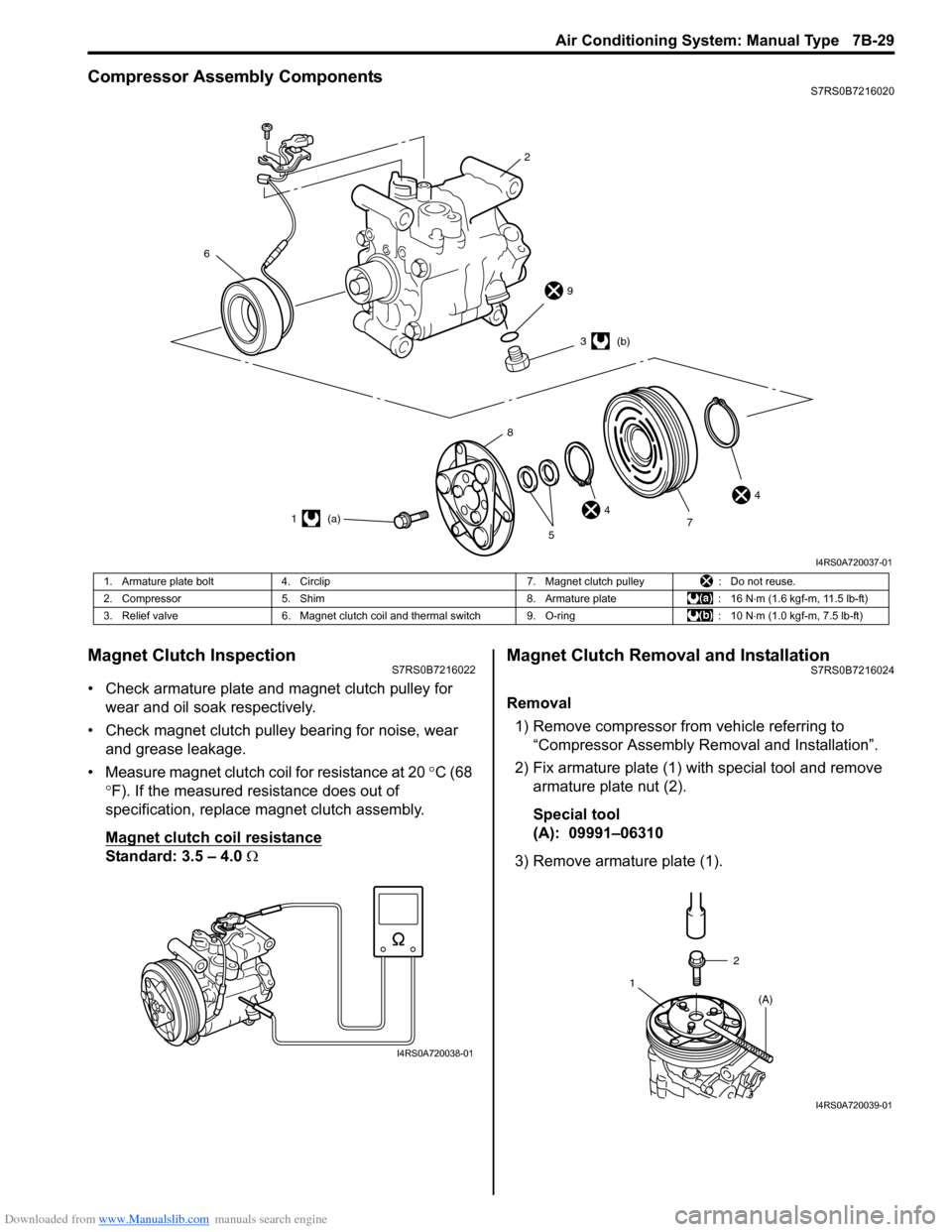
Compressor Assembly ComponentsS7RS0B7216020
Magnet Clutch InspectionS7RS0B7216022
• Check armature plate and magnet clutch pulley for wear and oil soak respectively.
• Check magnet clutch pulley bearing for noise, wear and grease leakage.
• Measure magnet clutch coil for resistance at 20 °C (68
° F). If the measured resistance does out of
specification, replace magnet clutch assembly.
Magnet clutch coil resistance
Standard: 3.5 – 4.0 Ω
Magnet Clutch Removal and InstallationS7RS0B7216024
Removal
1) Remove compressor from vehicle referring to “Compressor Assembly Re moval and Installation”.
2) Fix armature plate (1) with special tool and remove armature plate nut (2).
Special tool
(A): 09991–06310
3) Remove armature plate (1).
6
2
9
44
3 (b)
1 (a) 7
5
8
I4RS0A720037-01
1. Armature plate bolt
4. Circlip 7. Magnet clutch pulley: Do not reuse.
2. Compressor 5. Shim 8. Armature plate: 16 N⋅m (1.6 kgf-m, 11.5 lb-ft)
3. Relief valve 6. Magnet clutch coil and thermal switch 9. O-ring : 10 N⋅m (1.0 kgf-m, 7.5 lb-ft)
I4RS0A720038-01
2
1 (A)
I4RS0A720039-01
Page 1042 of 1496
Downloaded from www.Manualslib.com manuals search engine 8B-4 Air Bag System:
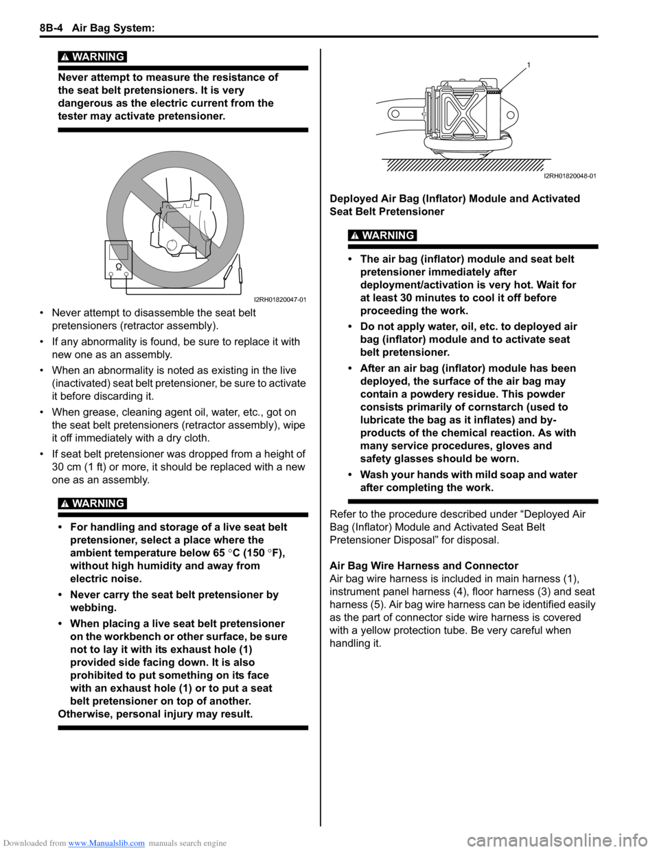
WARNING!
Never attempt to measure the resistance of
the seat belt pretensioners. It is very
dangerous as the electric current from the
tester may activate pretensioner.
• Never attempt to disassemble the seat belt
pretensioners (retractor assembly).
• If any abnormality is found, be sure to replace it with
new one as an assembly.
• When an abnormality is noted as existing in the live (inactivated) seat belt preten sioner, be sure to activate
it before discarding it.
• When grease, cleaning agent oil, water, etc., got on the seat belt pretensioners (r etractor assembly), wipe
it off immediately with a dry cloth.
• If seat belt pretensioner was dropped from a height of 30 cm (1 ft) or more, it should be replaced with a new
one as an assembly.
WARNING!
• For handling and storage of a live seat belt pretensioner, select a place where the
ambient temperature below 65 °C (150 ° F),
without high humidity and away from
electric noise.
• Never carry the seat belt pretensioner by webbing.
• When placing a live seat belt pretensioner on the workbench or other surface, be sure
not to lay it with its exhaust hole (1)
provided side facing down. It is also
prohibited to put something on its face
with an exhaust hole (1) or to put a seat
belt pretensioner on top of another.
Otherwise, personal injury may result.
Deployed Air Bag (Inflator) Module and Activated
Seat Belt Pretensioner
WARNING!
• The air bag (inflator) module and seat belt
pretensioner immediately after
deployment/activation is very hot. Wait for
at least 30 minutes to cool it off before
proceeding the work.
• Do not apply water, oil, etc. to deployed air bag (inflator) module and to activate seat
belt pretensioner.
• After an air bag (inflator) module has been deployed, the surface of the air bag may
contain a powdery residue. This powder
consists primarily of cornstarch (used to
lubricate the bag as it inflates) and by-
products of the chemical reaction. As with
many service procedures, gloves and
safety glasses should be worn.
• Wash your hands with mild soap and water after completing the work.
Refer to the procedure described under “Deployed Air
Bag (Inflator) Module and Activated Seat Belt
Pretensioner Disposal” for disposal.
Air Bag Wire Harness and Connector
Air bag wire harness is includ ed in main harness (1),
instrument panel harness (4), floor harness (3) and seat
harness (5). Air bag wire harness can be identified easily
as the part of connector side wire harness is covered
with a yellow protection tube. Be very careful when
handling it.
I2RH01820047-01
1
I2RH01820048-01
Page 1143 of 1496
Downloaded from www.Manualslib.com manuals search engine Air Bag System: 8B-105
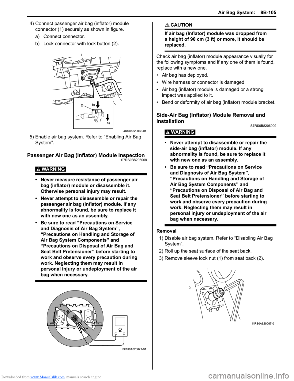
4) Connect passenger air bag (inflator) module connector (1) securely as shown in figure.
a) Connect connector.
b) Lock connector with lock button (2).
5) Enable air bag system. Refer to “Enabling Air Bag System”.
Passenger Air Bag (Inflator) Module InspectionS7RS0B8206008
WARNING!
• Never measure resistance of passenger air bag (inflator) module or disassemble it.
Otherwise personal injury may result.
• Never attempt to disassemble or repair the passenger air bag (inflator) module. If any
abnormality is found, be sure to replace it
with new one as an assembly.
• Be sure to read “Precautions on Service and Diagnosis of Air Bag System”,
“Precautions on Handling and Storage of
Air Bag System Components” and
“Precautions on Disposal of Air Bag and
Seat Belt Pretensioner” before starting to
work and observe every precaution during
work. Neglecting them may result in
personal injury or undeployment of the air
bag when necessary.
CAUTION!
If air bag (Inflator) module was dropped from
a height of 90 cm (3 ft) or more, it should be
replaced.
Check air bag (inflator) module appearance visually for
the following symptoms and if any one of them is found,
replace with a new one.
• Air bag has deployed.
• Wire harness or connector is damaged.
• Air bag (inflator) module is damaged or a strong impact was applied to it.
• Bend or deformity of air bag (inflator) module bracket.
Side-Air Bag (Inflator) Module Removal and
Installation
S7RS0B8206009
WARNING!
• Never attempt to disassemble or repair the side-air bag (inflator) module. If any
abnormality is found, be sure to replace it
with new one as an assembly.
• Be sure to read “Precautions on Service and Diagnosis of Air Bag System”,
“Precautions on Handling and Storage of
Air Bag System Components” and
“Precautions on Disposal of Air Bag and
Seat Belt Pretensioner” before starting to
work and observe every precaution during
work. Neglecting them may result in
personal injury or undeployment of the air
bag when necessary.
Removal
1) Disable air bag system. Re fer to “Disabling Air Bag
System”.
2) Roll up the seat surface of the seat back.
3) Remove sleeve lock nut (1) from seat back (2).
1
2
a)
b)
I4RS0A820066-01
I3RH0A820071-01
1
2
I4RS0A820067-01