2006 SUZUKI SWIFT start system
[x] Cancel search: start systemPage 1011 of 1496
Downloaded from www.Manualslib.com manuals search engine Air Conditioning System: Automatic Type 7B-63
DTC B1546: A/C Refrigerant Pressure MalfunctionS7RS0B7224018
DTC Detecting Condition and Trouble Area
DTC Troubleshooting
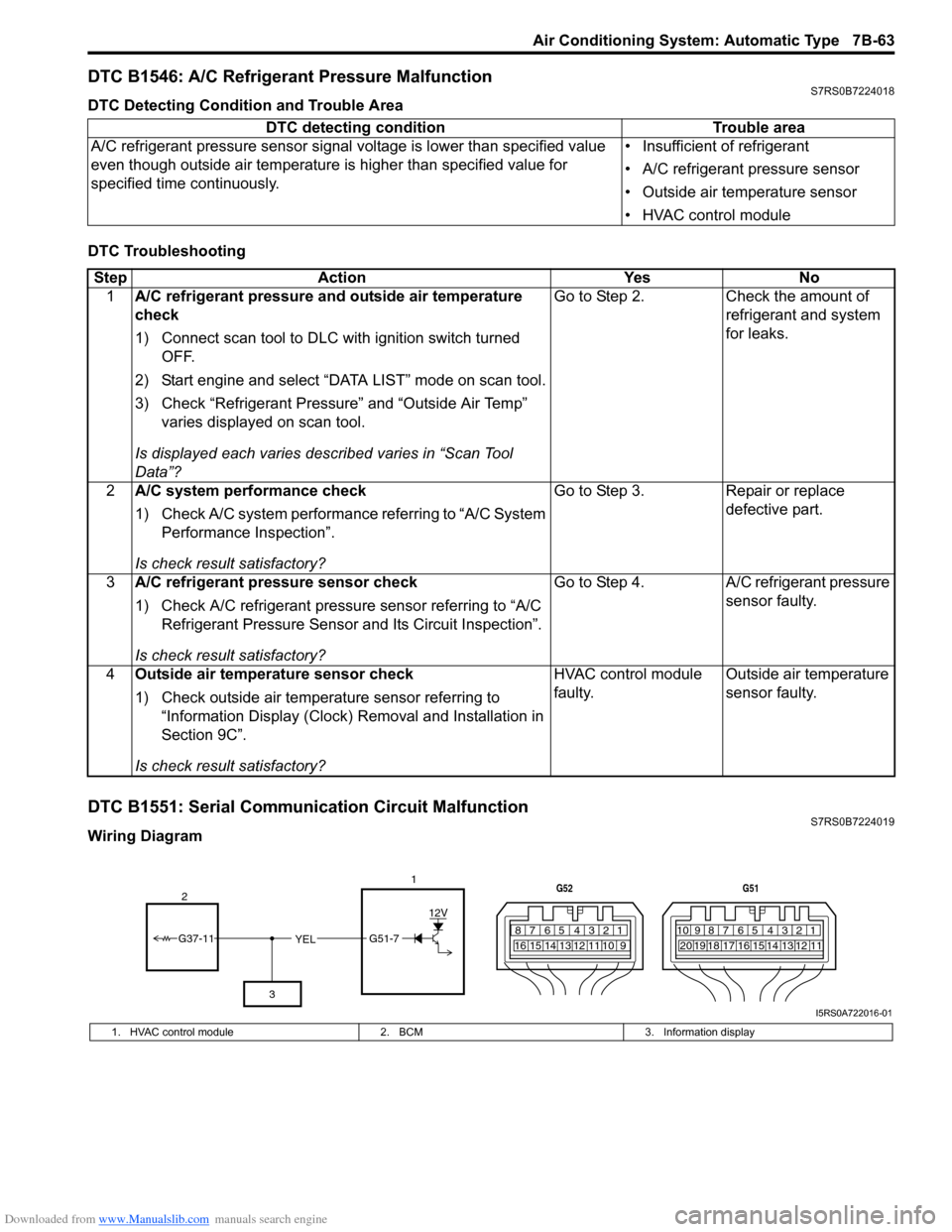
DTC B1551: Serial Communication Circuit MalfunctionS7RS0B7224019
Wiring DiagramDTC detecting condition Trouble area
A/C refrigerant pressure sensor signal voltage is lower t han specified value
even though outside air temperature is higher than specified value for
specified time continuously. • Insufficient of refrigerant
• A/C refrigerant pressure sensor
• Outside air temperature sensor
• HVAC control module
Step
Action YesNo
1 A/C refrigerant pressure and outside air temperature
check
1) Connect scan tool to DLC with ignition switch turned
OFF.
2) Start engine and select “DATA LIST” mode on scan tool.
3) Check “Refrigerant Pressure” and “Outside Air Temp” varies displayed on scan tool.
Is displayed each va ries described varies in “Scan Tool
Data”? Go to Step 2.
Check the amount of
refrigerant and system
for leaks.
2 A/C system performance check
1) Check A/C system performance referring to “A/C System
Performance Inspection”.
Is check result satisfactory? Go to Step 3.
Repair or replace
defective part.
3 A/C refrigerant pressure sensor check
1) Check A/C refrigerant pressure sensor referring to “A/C
Refrigerant Pressure Sensor and Its Circuit Inspection”.
Is check result satisfactory? Go to Step 4.
A/C refrigerant pressure
sensor faulty.
4 Outside air temperature sensor check
1) Check outside air temperature sensor referring to
“Information Display (Clock) Removal and Installation in
Section 9C”.
Is check result satisfactory? HVAC control module
faulty.
Outside air temperature
sensor faulty.
YEL17812910
65 431516 14 13 12 11
G52
789101920121112
65 431718 16 15 14 13
G51
G51-7
12V
2
3
G37-11
I5RS0A722016-01
1. HVAC control module 2. BCM3. Information display
Page 1013 of 1496
Downloaded from www.Manualslib.com manuals search engine Air Conditioning System: Automatic Type 7B-65
DTC Troubleshooting
DTC B1553: CAN Communication Signal MalfunctionS7RS0B7224021
DTC Detecting Condition and Trouble Area
DTC Troubleshooting
DTC B1557: Vehicle Speed Sensor Signal MalfunctionS7RS0B7224022
DTC Detecting Condition and Trouble Area
DTC TroubleshootingStep Action Yes No
1 Serial communication signal data check
1) Connect scan tool to DLC with ignition switch turned
OFF.
2) Start engine and select “DATA LIST” mode on scan tool.
3) Check “Refrigerant Pressure”, “Vehicle Speed”, “Coolant Temp” and “Outside Air Temp” varies displayed on scan
tool.
Is displayed each va ries described varies in “Scan Tool
Data”? Intermittent trouble.
Check for intermittent
referring to “Intermittent
and Poor Connection
Inspection in Section
00”.
Go to Step 2.
2 Serial communication signal check
1) Connect connectors to BCM and HVAC control module.
2) Using oscilloscope, check that serial communication
signal is outputted referring to “Reference waveform
No.8” of “Inspection of BCM and its Circuits in Section
10B”.
Is serial communication signal outputted at “G37-11”
terminal of BCM connector? HVAC control module
faulty.
BCM (included in
junction block
assembly) faulty.
DTC detecting condition
Trouble area
HVAC control module receives error code fr om BCM continuously.• CAN communication circuit
• BCM (included in junction block assembly)
•ECM
• HVAC control module
Step Action YesNo
1 DTC check
1) Connect scan tool to DLC with ignition switch turned
OFF.
2) Check ECM and BCM for DTC.
Is there DTC(s)? Go to applicable DTC
diag. flow.
Substitute a known-
good HVAC control
module and recheck.
DTC detecting condition
Trouble area
HVAC control module receives error code from BCM continuously. • VSS circuit
• VSS
• HVAC control module
Step Action YesNo
1 DTC check
1) Connect scan tool to DLC with ignition switch turned
OFF.
2) Check ECM for DTC.
Is there DTC P0500? Go to “DTC P0480: Fan
1 (Radiator Cooling
Fan) Control Circuit in
Section 1A”.
Substitute a known-
good HVAC control
module and recheck.
Page 1035 of 1496
Downloaded from www.Manualslib.com manuals search engine Seat Belts: 8A-4
Front Seat Belt Removal and InstallationS7RS0B8106002
WARNING!
• Never attempt to disassemble or repair the seat belt pretensioner (retractor
assembly). If any abnormality is found, be
sure to replace it with new one as an
assembly.
• Be sure to read “Precautions on Service and Diagnosis of Seat Belt” before starting
to work and observe every precaution
during work. Ne glecting them may result in
personal injury or una ctivation of the seat
belt pretensioner when necessary.
Removal
1) Disconnect negative (–) cable at battery.
2) Disable air bag system. Refer to “Disabling Air Bag System in Section 8B”.
3) Remove center pillar lower trim.
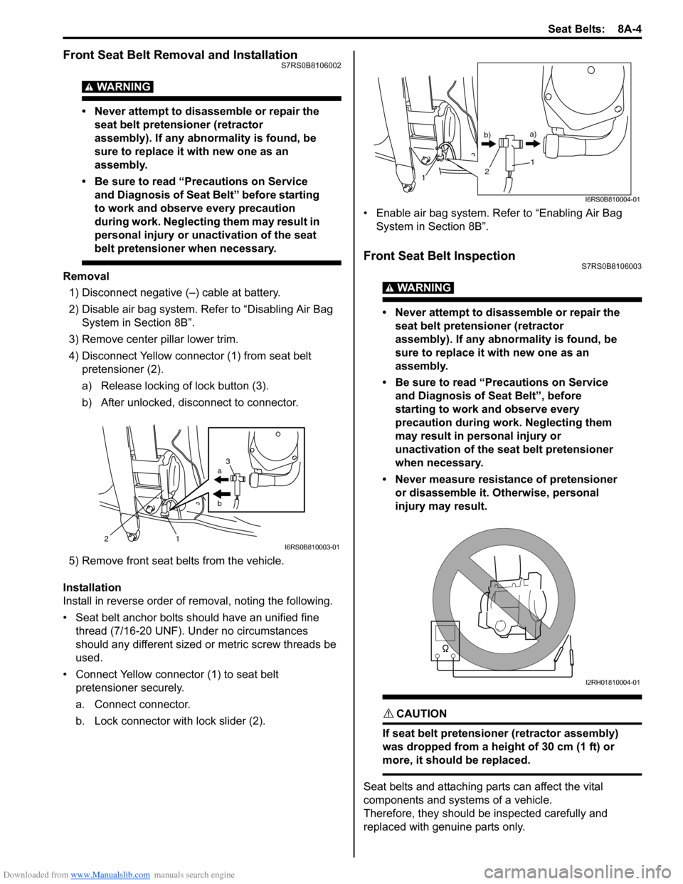
4) Disconnect Yellow connector (1) from seat belt pretensioner (2).
a) Release locking of lock button (3).
b) After unlocked, disconnect to connector.
5) Remove front seat belts from the vehicle.
Installation
Install in reverse order of removal, noting the following.
• Seat belt anchor bolts should have an unified fine thread (7/16-20 UNF). Under no circumstances
should any different sized or metric screw threads be
used.
• Connect Yellow connector (1) to seat belt pretensioner securely.
a. Connect connector.
b. Lock connector with lock slider (2). • Enable air bag system. Refer to “Enabling Air Bag
System in Section 8B”.
Front Seat Belt InspectionS7RS0B8106003
WARNING!
• Never attempt to disassemble or repair the seat belt pretensioner (retractor
assembly). If any abnormality is found, be
sure to replace it with new one as an
assembly.
• Be sure to read “Precautions on Service and Diagnosis of Seat Belt”, before
starting to work and observe every
precaution during work. Neglecting them
may result in personal injury or
unactivation of the seat belt pretensioner
when necessary.
• Never measure resistance of pretensioner or disassemble it. Otherwise, personal
injury may result.
CAUTION!
If seat belt pretensioner (retractor assembly)
was dropped from a height of 30 cm (1 ft) or
more, it should be replaced.
Seat belts and attaching parts can affect the vital
components and systems of a vehicle.
Therefore, they should be inspected carefully and
replaced with genuine parts only.
a
b
21 3I6RS0B810003-01
1
1
2
b)
a)
I6RS0B810004-01
I2RH01810004-01
Page 1039 of 1496
Downloaded from www.Manualslib.com manuals search engine Air Bag System: 8B-1
Restraint
Air Bag System
Precautions
Precautions on Service and Diagnosis of Air
Bag System
S7RS0B8200001
WARNING!
• If the air bag system and another vehicle system both need repair, SUZUKI
recommends that the air bag system be
repaired first, to help avoid unintended air
bag system activation.
• Do not modify the steering wheel, dashboard, both front seat or any other on
or around air bag system components.
Modifications can adversely affect air bag
system performance and lead to injury.
• Be sure to follow the procedures described in this section. Failure to follow
procedures could result in possible air bag
system activation, personal injury or
unneeded air bag system repairs.
• WARNING / CAUTION labels are attached on each
part of air bag system components (SDM, air bag
(inflator) modules and seat belt pretensioners). Be
sure to follow the instructions.
• Many of service procedures require disconnection of
“A/BAG” fuse and air bag (inflator) module(s) (driver,
passenger, side of both si des and curtain of both
sides) from initiator circuit to avoid an accidental
deployment.
• Do not apply power to the air bag system unless all components are connected or a diagnostic flow
requests it, as this will set a DTC.
• The “Air Bag Diagnostic S ystem Check” must be the
starting point of any air bag diagnostics. The “Air Bag
Diagnostic System Check” will verify proper “AIR
BAG” warning right operatio n and will lead you to the
correct flow to diagnose any air bag malfunctions.
Bypassing these procedures may result in extended
diagnostic time, incorrect diagnosis, and incorrect
parts replacements. • Never use air bag component parts from another
vehicle.
• If the vehicle will be exposed to temperatures over 93
° C (200 °F) (for example, during a paint baking
process), remove the air bag system components
beforehand to avoid component damage or
unintended system activation.
• When handling the air bag (inflator) modules (driver, passenger, side of both si des and curtain of both
sides), seat belt pretensio ners (driver and passenger),
SDM, forward-sensor or side-sensor, be careful not to
drop it or apply an impact to it. If an excessive impact
was applied (e.g., SDM, forward-sensor and side-
sensor are dropped, air bag (inflator) module is
dropped from a height of 90 cm (3 ft) or more, seat
belt pretensioner (retractor assembly) is dropped from
a height of 30 cm (1 ft) or more), never attempt
disassembly or repair but replace it with a new one.
• When using electric welding, be sure to disconnect air bag (inflator) module connectors (driver, passenger,
side of both sides and curtain of both sides) and seat
belt pretensioner connectors (driver and passenger)
respectively.
• When applying paint around the air bag system related parts, use care so that the harness or
connector will not be expo sed to the paint mist.
• Never expose air bag system component parts directly to hot air (drying or baking the vehicle after
painting) or flames.
WARNING!
When performing service on or around air
bag system components or air bag wiring,
follow the procedures listed in “Disabling Air
Bag System” to temporarily disable the air
bag system.
Failure to follow procedures could result in
possible air bag system activation, personal
injury or unneeded air bag system repairs.
Page 1048 of 1496
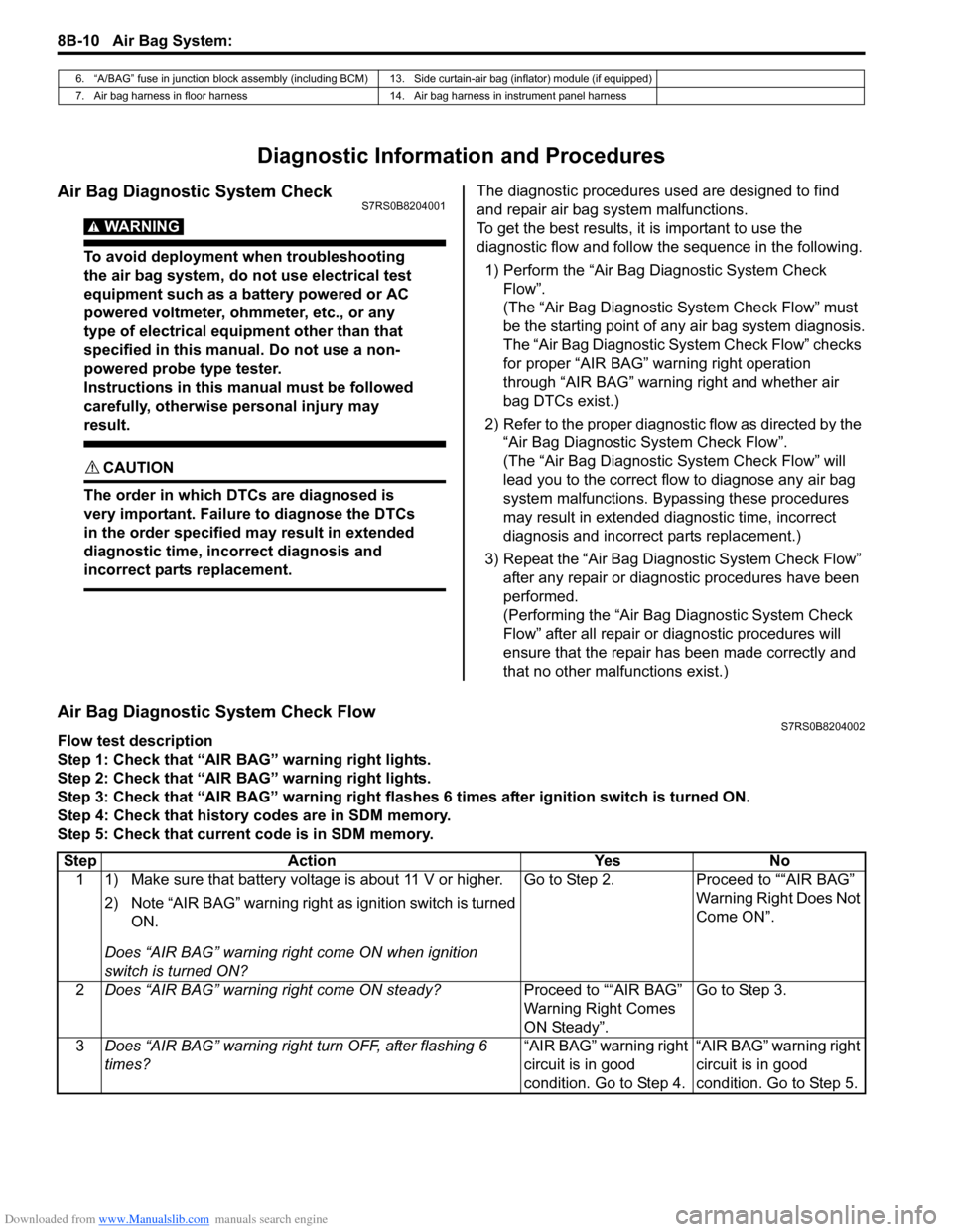
Downloaded from www.Manualslib.com manuals search engine 8B-10 Air Bag System:
Diagnostic Information and Procedures
Air Bag Diagnostic System CheckS7RS0B8204001
WARNING!
To avoid deployment when troubleshooting
the air bag system, do not use electrical test
equipment such as a battery powered or AC
powered voltmeter, ohmmeter, etc., or any
type of electrical equipment other than that
specified in this manual. Do not use a non-
powered probe type tester.
Instructions in this manual must be followed
carefully, otherwise personal injury may
result.
CAUTION!
The order in which DTCs are diagnosed is
very important. Failure to diagnose the DTCs
in the order specified may result in extended
diagnostic time, incorrect diagnosis and
incorrect parts replacement.
The diagnostic procedures used are designed to find
and repair air bag system malfunctions.
To get the best results, it is important to use the
diagnostic flow and follow the sequence in the following.1) Perform the “Air Bag Diagnostic System Check Flow”.
(The “Air Bag Diagnostic System Check Flow” must
be the starting point of any air bag system diagnosis.
The “Air Bag Diagnostic System Check Flow” checks
for proper “AIR BAG” warning right operation
through “AIR BAG” warning right and whether air
bag DTCs exist.)
2) Refer to the proper diagnost ic flow as directed by the
“Air Bag Diagnostic System Check Flow”.
(The “Air Bag Diagnostic System Check Flow” will
lead you to the correct flow to diagnose any air bag
system malfunctions. Bypassing these procedures
may result in extended diagnostic time, incorrect
diagnosis and incorrect parts replacement.)
3) Repeat the “Air Bag Diagnostic System Check Flow” after any repair or diagnostic procedures have been
performed.
(Performing the “Air Bag Diagnostic System Check
Flow” after all repair or diagnostic procedures will
ensure that the repair has been made correctly and
that no other malfunctions exist.)
Air Bag Diagnostic System Check FlowS7RS0B8204002
Flow test description
Step 1: Check that “AIR BAG” warning right lights.
Step 2: Check that “AIR BAG” warning right lights.
Step 3: Check that “AIR BAG” warning right flas hes 6 times after ignition switch is turned ON.
Step 4: Check that history codes are in SDM memory.
Step 5: Check that current code is in SDM memory.
6. “A/BAG” fuse in junction block assembly (including BCM) 13. Side curtain-air bag (inflator) module (if equipped)
7. Air bag harness in floor harness 14. Air bag harness in instrument panel harness
Step Action YesNo
1 1) Make sure that battery voltage is about 11 V or higher.
2) Note “AIR BAG” warning right as ignition switch is turned
ON.
Does “AIR BAG” warning ri ght come ON when ignition
switch is turned ON? Go to Step 2.
Proceed to ““AIR BAG”
Warning Right Does Not
Come ON”.
2 Does “AIR BAG” warning right come ON steady? Proceed to ““AIR BAG”
Warning Right Comes
ON Steady”.Go to Step 3.
3 Does “AIR BAG” warning right turn OFF, after flashing 6
times? “AIR BAG” warning right
circuit is in good
condition. Go to Step 4.“AIR BAG” warning right
circuit is in good
condition. Go to Step 5.
Page 1052 of 1496
Downloaded from www.Manualslib.com manuals search engine 8B-14 Air Bag System:
CAUTION!
• Be sure to perform “Air Bag Diagnostic System Check” before starting diagnosis according to flow.
• When measurement of resistance or voltage is required in this flow, use a tester along with a correct terminal adapter from special tool (Connector test adapter kit).
• When a check for proper connection is required, refer to “Inspection of Intermittent and Poor Connections”.
• If there is open circuit in the air bag wire harnes s, connector or terminal is found damaged, replace
the wire harness, connector and terminal as an assembly.
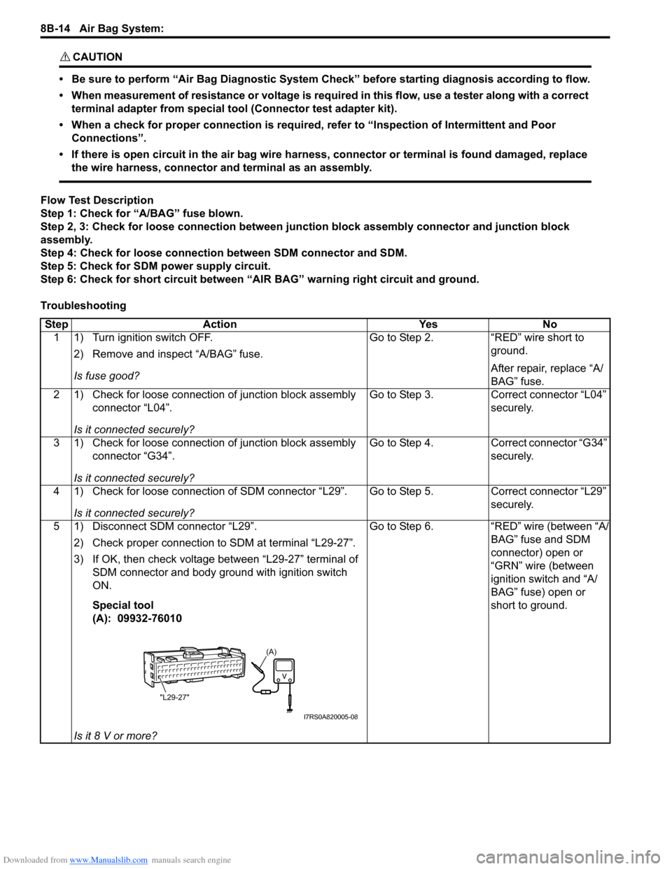
Flow Test Description
Step 1: Check for “A/BAG” fuse blown.
Step 2, 3: Check for loose connection between junction block assembly connector and junction block
assembly.
Step 4: Check for loose connection between SDM connector and SDM.
Step 5: Check for SDM power supply circuit.
Step 6: Check for short circuit between “A IR BAG” warning right circuit and ground.
Troubleshooting Step Action YesNo
1 1) Turn ignition switch OFF.
2) Remove and inspect “A/BAG” fuse.
Is fuse good? Go to Step 2.
“RED” wire short to
ground.
After repair, replace “A/
BAG” fuse.
2 1) Check for loose connection of junction block assembly connector “L04”.
Is it connected securely? Go to Step 3.
Correct connector “L04”
securely.
3 1) Check for loose connection of junction block assembly connector “G34”.
Is it connected securely? Go to Step 4.
Correct connector “G34”
securely.
4 1) Check for loose connection of SDM connector “L29”. Is it connected securely? Go to Step 5.
Correct connector “L29”
securely.
5 1) Disconnect SDM connector “L29”. 2) Check proper connection to SDM at terminal “L29-27”.
3) If OK, then check voltage between “L29-27” terminal of SDM connector and body ground with ignition switch
ON.
Special tool
(A): 09932-76010
Is it 8 V or more? Go to Step 6.
“RED” wire (between “A/
BAG” fuse and SDM
connector) open or
“GRN” wire (between
ignition switch and “A/
BAG” fuse) open or
short to ground.
(A)
"L29-27"
I7RS0A820005-08
Page 1054 of 1496
Downloaded from www.Manualslib.com manuals search engine 8B-16 Air Bag System:
CAUTION!
• Be sure to perform “Air Bag Diagnostic System Check” before starting diagnosis according to flow.
• When measurement of resistance or voltage is required in this flow, use a tester along with a correct terminal adapter from special tool (Connector test adapter kit).
• When a check for proper connection is required, refer to “Inspection of Intermittent and Poor Connections”.
• If there is open circuit in the air bag wire harnes s, connector or terminal is found damaged, replace
the wire harness, connector and terminal as an assembly.
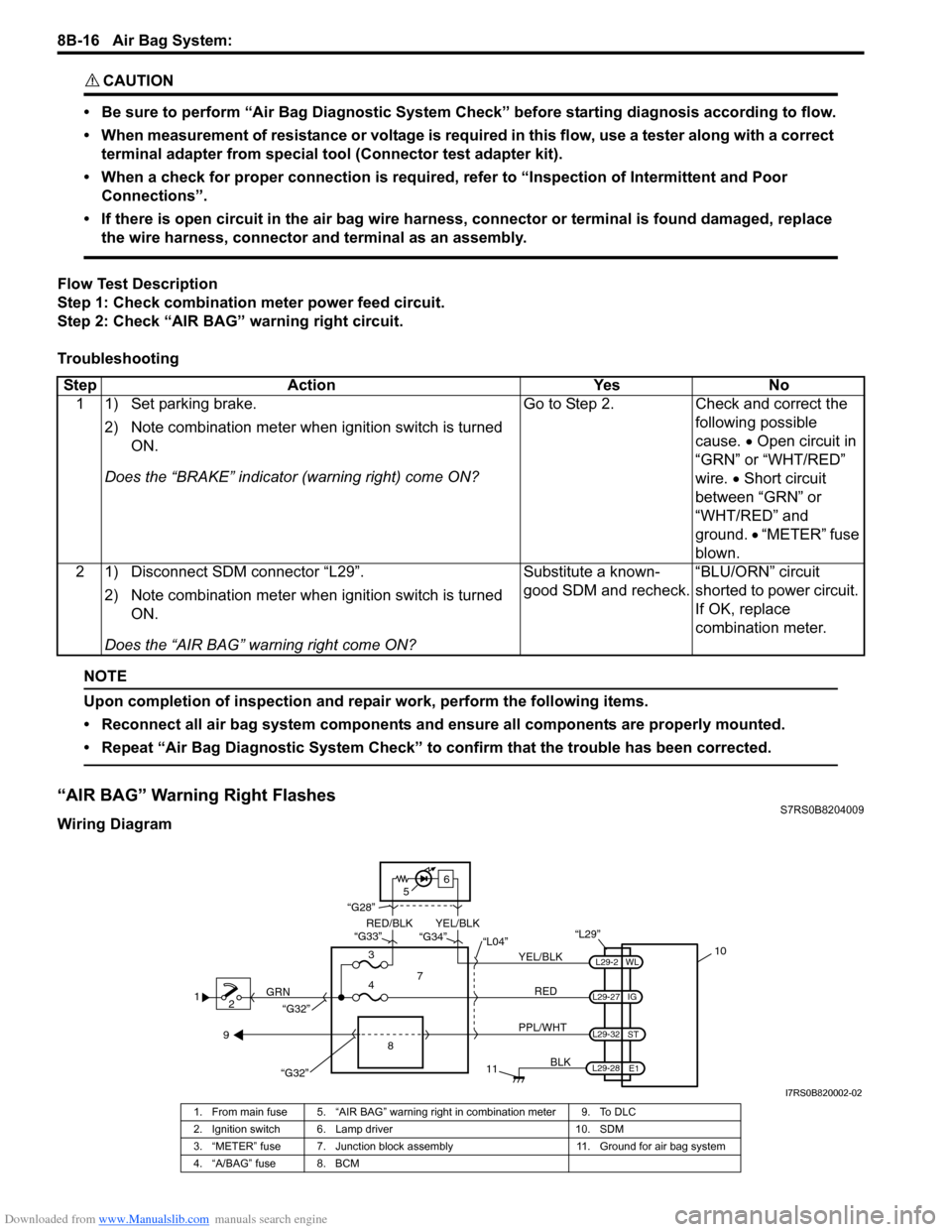
Flow Test Description
Step 1: Check combination meter power feed circuit.
Step 2: Check “AIR BAG” warning right circuit.
Troubleshooting
NOTE
Upon completion of inspection and repair work, perform the following items.
• Reconnect all air bag system components and ensure all components are properly mounted.
• Repeat “Air Bag Diagnostic System Check” to confirm that the trouble has been corrected.
“AIR BAG” Warning Right FlashesS7RS0B8204009
Wiring Diagram Step Action Yes No
1 1) Set parking brake.
2) Note combination me ter when ignition switch is turned
ON.
Does the “BRAKE” in dicator (warning right) come ON? Go to Step 2. Check and correct the
following possible
cause. • Open circuit in
“GRN” or “WHT/RED”
wire. • Short circuit
between “GRN” or
“WHT/RED” and
ground. • “METER” fuse
blown.
2 1) Disconnect SDM connector “L29”.
2) Note combination me ter when ignition switch is turned
ON.
Does the “AIR BAG” warning right come ON? Substitute a known-
good SDM and recheck.
“BLU/ORN” circuit
shorted to power circuit.
If OK, replace
combination meter.
1
2 GRN
11
BLK
L29-27
L29-2
L29-28 WL
E1
IG
L29-32
ST
10
8
“L29”
RED
PPL/WHT
7
3
4 “L04”
“G34”
“G33”
“G28”
“G32”
5 6
“G32”
YEL/BLK
YEL/BLK
RED/BLK
9
I7RS0B820002-02
1. From main fuse 5. “AIR BAG” warning right in combination meter 9. To DLC
2. Ignition switch 6. Lamp driver 10. SDM
3. “METER” fuse 7. Junction block assembly 11. Ground for air bag system
4. “A/BAG” fuse 8. BCM
Page 1055 of 1496
Downloaded from www.Manualslib.com manuals search engine Air Bag System: 8B-17
CAUTION!
• Be sure to perform “Air Bag Diagnostic System Check” before starting diagnosis according to flow.
• When measurement of resistance or voltage is required in this flow, use a tester along with a correct terminal adapter from special tool (Connector test adapter kit).
• When a check for proper connection is required, refer to “Inspection of Intermittent and Poor Connections”.
• If there is open circuit in the air bag wire harnes s, connector or terminal is found damaged, replace
the wire harness, connector and terminal as an assembly.
Flow Test Description
Check for short circuit between diag nosis switch circuit and ground.
Troubleshooting
NOTE
Upon completion of inspection and repair work, perform the following items.
• Reconnect all air bag system components and ensure all components are properly mounted.
• Repeat “Air Bag Diagnostic System Check” to confirm that the trouble has been corrected.
DTC B1013: SDM faultS7RS0B8204010
DTC Will Set when
An internal SDM fault is detected by SDM.
NOTE
DTC B1013 can never be cleared once it has been set.
DTC Troubleshooting 1) Turn ignition switch OFF.
2) Replace SDM.
3) Repeat “Air Bag Diagnostic System Check”.
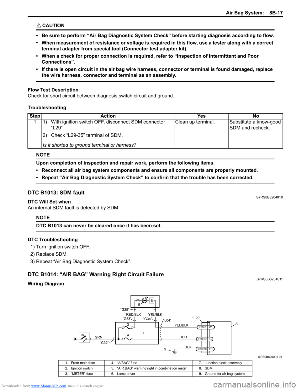
DTC B1014: “AIR BAG” Warning Right Circuit FailureS7RS0B8204011
Wiring DiagramStep Action Yes No
1 1) With ignition switch OFF, disconnect SDM connector “L29”.
2) Check “L29-35” terminal of SDM.
Is it shorted to ground terminal or harness? Clean up terminal. Substitute a know-good
SDM and recheck.
12 GRN
9
BLK
L29-2
L29-27
L29-28 IG
E1
WL
8
“L29”
RED
7
3
4 “L04”
“G34”
“G33”
“G28”
“G32”
5 6
YEL/BLK
YEL/BLK
RED/BLK
I7RS0B820004-04
1. From main fuse 4. “A/BAG” fuse
7. Junction block assembly
2. Ignition switch 5. “AIR BAG” warning right in combination meter 8. SDM
3. “METER” fuse 6. Lamp driver 9. Ground for air bag system