2006 SUZUKI SWIFT start system
[x] Cancel search: start systemPage 719 of 1496

Downloaded from www.Manualslib.com manuals search engine Automatic Transmission/Transaxle: 5A-75
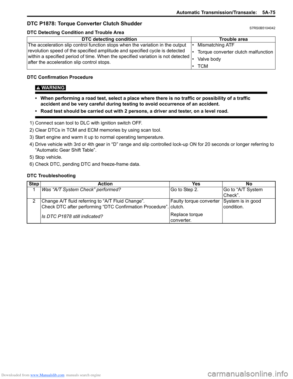
DTC P1878: Torque Converter Clutch ShudderS7RS0B5104042
DTC Detecting Condition and Trouble Area
DTC Confirmation Procedure
WARNING!
• When performing a road test, select a place where there is no traffic or possibility of a traffic accident and be very careful during testing to avoid occurrence of an accident.
• Road test should be carried out with 2 persons, a driver and tester, on a level road.
1) Connect scan tool to DLC with ignition switch OFF.
2) Clear DTCs in TCM and ECM memories by using scan tool.
3) Start engine and warm it up to normal operating temperature.
4) Drive vehicle with 3rd or 4th gear in “D” range and slip c ontrolled lock-up ON for 20 seconds or longer referring to
“Automatic Gear Shift Table”.
5) Stop vehicle.
6) Check DTC, pending DTC and freeze-frame data.
DTC Troubleshooting DTC detecting condition
Trouble area
The acceleration slip control function stops when the variation in the output
revolution speed of the specified amp litude and specified cycle is detected
within a specified period of time. When t he specified variation is not detected
after the acceleration slip control stops. • Mismatching ATF
• Torque converter clutch malfunction
• Valve body
•TCM
Step
Action YesNo
1 Was “A/T System Check” performed? Go to Step 2.Go to “A/T System
Check”.
2 Change A/T fluid referring to “A/T Fluid Change”. Check DTC after performing “DTC Confirmation Procedure”.
Is DTC P1878 still indicated? Faulty torque converter
clutch.
Replace torque
converter.System is in good
condition.
Page 722 of 1496

Downloaded from www.Manualslib.com manuals search engine 5A-78 Automatic Transmission/Transaxle:
DTC P2763: Torque Converter Clutch Pressure Control Solenoid Control Circuit HighS7RS0B5104043
Wiring Diagram
DTC Detecting Condition and Trouble Area
DTC Confirmation Procedure
WARNING!
• When performing a road test, select a place where there is no traffic or possibility of a traffic
accident and be very careful during testing to avoid occurrence of an accident.
• Road test should be carried out with 2 persons, a driver and a tester, on a level road.
1) Connect scan tool to DLC with ig nition switch OFF, if available.
2) Clear DTC in TCM memory.
3) Start engine.
4) Keep engine running at idle speed in “P” range for 10 seconds or more.
5) Check DTC.
DTC Troubleshooting
1. TCM 3. A/T
2. TCC lock-up pressure control solenoid valve [A]: Terminal arrangement of TCM connector (viewed from harness side)
DTC detecting conditionTrouble area
Voltage of TCC lock-up pressure control solenoid valve TCM
terminal is high although TCM is commanding TCC lock-up
pressure control sole noid to turn OFF. • TCC lock-up pressure contro
l solenoid valve circuit
shorted to ground
• Malfunction of TCC lock-up pressure control solenoid valve
•TCM
12V
C34-5
C34-3
WHT/BLU
WHT/BLK
3
1
2
53
C34C35
[A]
I4RS0A510019-01
Step
Action YesNo
1 Was “A/T System Check” performed? Go to Step 2.Go to “A/T System
Check”.
Page 724 of 1496

Downloaded from www.Manualslib.com manuals search engine 5A-80 Automatic Transmission/Transaxle:
DTC P2764: Torque Converter Clutch Circuit Pressure Control Solenoid Control Circuit LowS7RS0B5104044
Wiring Diagram
DTC Detecting Condition and Trouble Area
DTC Confirmation Procedure
WARNING!
• When performing a road test, select a place where there is no traffic or possibility of a traffic
accident and be very careful during testing to avoid occurrence of an accident.
• Road test should be carried out with 2 persons, a driver and a tester, on a level road.
1) Connect scan tool to DLC with ig nition switch OFF, if available.
2) Clear DTC in TCM memory.
3) Start engine.
4) Keep engine running at idle speed in “P” range for 20 seconds or more.
5) Check DTC.
DTC Troubleshooting
1. TCM 3. A/T
2. TCC pressure control solenoid valve [A]: Terminal arrangement of TCM connector (viewed from harness side)
DTC detecting condition Trouble area
Voltage of TCC lock-up pressure control solenoid valve TCM
terminal is low although TCM is commanding TCC lock-up
pressure control sole noid to turn ON. • TCC lock-up pressure contro
l solenoid valve circuit
shorted to ground
• Malfunction of TCC lock-up pressure control solenoid valve
•TCM
12V
C34-5
C34-3
WHT/BLU
WHT/BLK
3
1
2
53
C34C35
[A]
I4RS0A510019-01
Step
Action YesNo
1 Was “A/T System Check” performed? Go to Step 2.Go to “A/T System
Check”.
Page 739 of 1496

Downloaded from www.Manualslib.com manuals search engine Automatic Transmission/Transaxle: 5A-95
5) Shift select lever to “N” position.
NOTE
If select lever is in “P” position, shift select
lever referring to “Select Lever Inspection”.
6) Install cable casing cap (3) to selector bracket (4).
7) Connect cable end (1) to interlock cam (2) with ignition switch turned to ACC position.
8) Drive lock button (5) in cable end until it locks cable expansion and contraction.
9) With select lever set at “P ” position, turn ignition key
to ACC position and then check for the following
conditions.
• With knob button released, ignition key can be turned from ACC position to LOCK position.
• With knob button pressed, ignition key cannot be
turned from ACC position to LOCK position.
10) Install steering column cover. 11) If the vehicle is equipped with air bag system, connect negative cable at battery and enable air bag
system, referring to “Enabling Air Bag System in
Section 8B”.
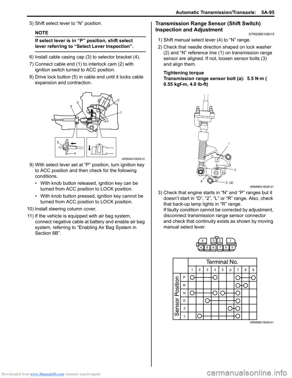
Transmission Range Sensor (Shift Switch)
Inspection and Adjustment
S7RS0B5106015
1) Shift manual select lever (4) to “N” range.
2) Check that needle direction shaped on lock washer (2) and “N” reference line (1) on transmission range
sensor are aligned. If not, loosen sensor bolts (3)
and align them.
Tightening torque
Transmission range sensor bolt (a): 5.5 N·m (
0.55 kgf-m, 4.0 lb-ft)
3) Check that engine starts in “N” and “P” ranges but it doesn’t start in “D”, “2”, “L” or “R” range. Also, check
that back-up lamp lights in “R” range.
If faulty condition cannot be corrected by adjustment,
disconnect transmission range sensor connector
and check that continuity ex ists as shown by moving
manual select lever.
3
4 1
2
3 5
I4RS0A510055-01
I3RM0B510038-01
4
3
2
1
98 76 5
12 345
6789
P
R N
D 2
L
I3RM0B510039-01
Page 855 of 1496

Downloaded from www.Manualslib.com manuals search engine Clutch: 5C-3
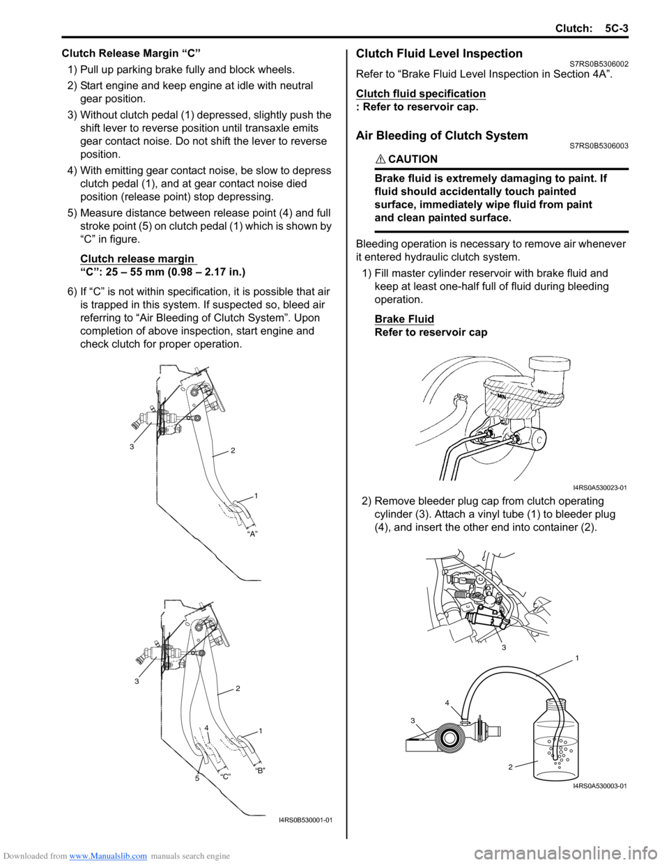
Clutch Release Margin “C”1) Pull up parking brake fully and block wheels.
2) Start engine and keep engine at idle with neutral gear position.
3) Without clutch pedal (1) dep ressed, slightly push the
shift lever to re verse position until transaxle emits
gear contact noise. Do not shift the lever to reverse
position.
4) With emitting gear contact noise, be slow to depress clutch pedal (1), and at gear contact noise died
position (release point) stop depressing.
5) Measure distance between release point (4) and full stroke point (5) on clutch pedal (1) which is shown by
“C” in figure.
Clutch release margin
“C”: 25 – 55 mm (0.98 – 2.17 in.)
6) If “C” is not within specificat ion, it is possible that air
is trapped in this system. If suspected so, bleed air
referring to “Air Bleeding of Clutch System”. Upon
completion of above inspection, start engine and
check clutch for proper operation.
Clutch Fluid Level InspectionS7RS0B5306002
Refer to “Brake Fluid Level Inspection in Section 4A”.
Clutch fluid specification
: Refer to reservoir cap.
Air Bleeding of Clutch SystemS7RS0B5306003
CAUTION!
Brake fluid is extremely damaging to paint. If
fluid should accidentally touch painted
surface, immediately wipe fluid from paint
and clean painted surface.
Bleeding operation is necessary to remove air whenever
it entered hydraulic clutch system.
1) Fill master cylinder reservoir with brake fluid and keep at least one-half full of fluid during bleeding
operation.
Brake Fluid
Refer to reservoir cap
2) Remove bleeder plug cap from clutch operating cylinder (3). Attach a vinyl tube (1) to bleeder plug
(4), and insert the other end into container (2).
2
1
“A”
3
2
1
3
“B”
“C”
4
5
I4RS0B530001-01
I4RS0A530023-01
3 4 1
2
3
I4RS0A530003-01
Page 867 of 1496

Downloaded from www.Manualslib.com manuals search engine Table of Contents 6- i
6
Section 6
CONTENTS
Steering
Precautions ................................................. 6-1
Precautions............................................................. 6-1
Precautions on Steering........................................ 6-1
Steering General Diagnosi s.................... 6A-1
Precautions........................................................... 6A-1
Precautions for Steering Diagnosis ..................... 6A-1
Diagnostic Information and Procedures ............ 6A-2 Steering Symptom Diagnosis .............................. 6A-2
Steering Wheel and Column ................... 6B-1
Precautions........................................................... 6B-1
Service Precautions of Steering Wheel and Column.............................................................. 6B-1
General Description ............................................. 6B-1 Steering Wheel and Column Construction .......... 6B-1
Diagnostic Information and Procedures ............ 6B-2 Checking Steering Column for Accident Damage ............................................................ 6B-2
Repair Instructions .............................................. 6B-3 Steering Wheel and Column Construction .......... 6B-3
Steering Wheel Removal and Installation ........... 6B-4
Contact Coil Cable Assembly Removal and Installation ......................................................... 6B-5
Centering Contact Coil Cable Assembly ............. 6B-6
Contact Coil Cable Assembly Inspection ............ 6B-6
Steering Angle Sensor Removal and Installation ......................................................... 6B-6
Steering Angle Sensor Inspection ....................... 6B-6
Steering Column Removal and Installation ......... 6B-7
Steering Column Inspecti on ................................ 6B-8
Ignition Switch Cylinder Assembly Removal and Installation (Non- Keyless Start Model)...... 6B-9
Steering Lock Assembly (Ignition Switch) Removal and Installation................................... 6B-9
Steering Lower Shaft Removal and Installation ....................................................... 6B-10
Specifications ..................................................... 6B-11
Tightening Torque Specifications ...................... 6B-11
Special Tools and Equipmen t ........................... 6B-11
Special Tool ...................................................... 6B-11
Power Assisted Steering System........... 6C-1
Precautions........................................................... 6C-1 Steering System Note .........................................6C-1
Precautions in Diagnosing Troubles ...................6C-1
General Description .............................................6C-2 P/S System Description ......................................6C-2
EPS Diagnosis General Descr iption ...................6C-3
On-Board Diagnostic System Description ...........6C-3
Schematic and Routing Diagram ........................6C-4 EPS System Wiring Circuit Diagram ...................6C-4
Diagnostic Information and Procedures ............6C-5 EPS System Check .............. ...............................6C-5
“EPS” Warning Light Check . ...............................6C-8
DTC Check..........................................................6C-8
DTC Clearance ...................................................6C-9
DTC Table ...........................................................6C-9
Scan Tool Data .................................................6C-11
Visual Inspection ...............................................6C-12
P/S System Symptom Diagnosis ......................6C-12
Serial Data Link Circuit Check ..........................6C-13
“EPS” Warning Light Do es Not Come ON with
Ignition Switch Turn ed ON before Engine
Starts ...............................................................6C-15
“EPS” Warning Light Remains ON Steady after Engine Starts ..........................................6C-16
DTC C1113: Steering Torque Sensor (Main and Sub) Circuit Correlation ............................6C-17
DTC C1114: Steering Torque Sensor Reference Power Supply Circuit .....................6C-19
DTC C1117: Steering Torque Sensor Failure Signal Circuit Low ...........................................6C-21
DTC C1118: Steering Torque Sensor Failure Signal Circuit High...........................................6C-22
DTC C1119: Steering Torque Sensor Power Supply Circuit ..................................................6C-24
DTC C1121 / C1123 / C1124: VSS Circuit
Failure .............................................................6C-26
DTC C1122: Engine Speed Signal....................6C-28
DTC C1141 / C1142 / C1143 / C1145: P/S Motor Circuit Failure ........................................6C-30
DTC C1153: P/S Control Module Power Supply Circuit Voltage Low .............................6C-32
DTC C1155: P/S Control Module Failure ..........6C-33
P/S Control Module Power Supply and Ground Circuit Check ......................................6C-34
Inspection of P/S Control Module and Its Circuits ............................................................6C-35
Page 880 of 1496

Downloaded from www.Manualslib.com manuals search engine 6B-9 Steering Wheel and Column:
Ignition Switch Cylinder Assembly Removal
and Installation (Non- Keyless Start Model)
S7RS0B6206008
Removal1) Disconnect negative (–) cable at battery.
2) Disable air bag system referring to “Disabling Air Bag System in Section 8B”.
3) Remove steering column upper and lower covers.
4) Remove immobilizer co ntrol module referring to
“Immobilizer Control Modu le (ICM) Removal and
Installation in Section 10C”.
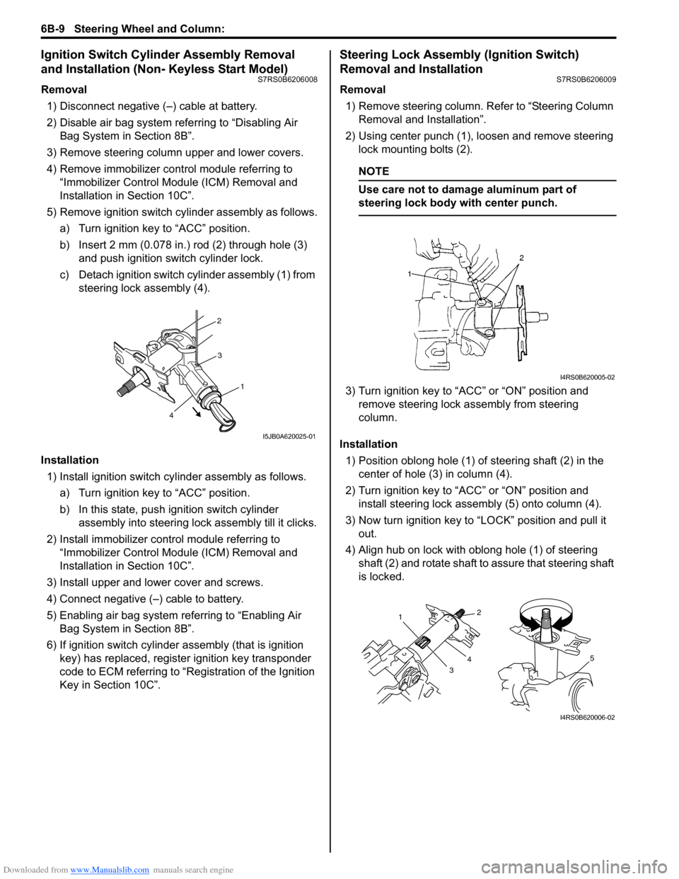
5) Remove ignition switch cy linder assembly as follows.
a) Turn ignition key to “ACC” position.
b) Insert 2 mm (0.078 in.) rod (2) through hole (3) and push ignition switch cylinder lock.
c) Detach ignition switch cylinder assembly (1) from steering lock assembly (4).
Installation 1) Install ignition switch cy linder assembly as follows.
a) Turn ignition key to “ACC” position.
b) In this state, push ignition switch cylinder assembly into steering lock assembly till it clicks.
2) Install immobilizer cont rol module referring to
“Immobilizer Control Modu le (ICM) Removal and
Installation in Section 10C”.
3) Install upper and lower cover and screws.
4) Connect negative (–) cable to battery.
5) Enabling air bag system referring to “Enabling Air Bag System in Section 8B”.
6) If ignition switch cylinder assembly (that is ignition
key) has replaced, register ignition key transponder
code to ECM referring to “R egistration of the Ignition
Key in Section 10C”.
Steering Lock Assembly (Ignition Switch)
Removal and Installation
S7RS0B6206009
Removal
1) Remove steering column. Refer to “Steering Column
Removal and Installation”.
2) Using center punch (1), loosen and remove steering lock mounting bolts (2).
NOTE
Use care not to damage aluminum part of
steering lock body with center punch.
3) Turn ignition key to “ACC” or “ON” position and remove steering lock a ssembly from steering
column.
Installation 1) Position oblong hole (1) of steering shaft (2) in the center of hole (3) in column (4).
2) Turn ignition key to “ACC” or “ON” position and install steering lock assemb ly (5) onto column (4).
3) Now turn ignition key to “LOCK” position and pull it out.
4) Align hub on lock with oblong hole (1) of steering shaft (2) and rotate shaft to assure that steering shaft
is locked.
2
3
1
4
I5JB0A620025-01
I4RS0B620005-02
1
32
4
5
I4RS0B620006-02
Page 883 of 1496

Downloaded from www.Manualslib.com manuals search engine Power Assisted Steering System: 6C-1
Steeri ng
Power Assisted Steering System
Precautions
Steering System NoteS7RS0B6300001
NOTE
All steering gear fasteners are important attaching parts in that they could affect the performance of
vital parts and systems, and/or could result in major repair expense. They must be replaced with one of
the same part number or with an equivalent part if replacement becomes necessary. Do not use a
replacement part of lesser quality or substitute design. Torque values must be used as specified
during reassembly to assure proper retention of these parts.
Precautions in Diagnosing TroublesS7RS0B6300002
• Take a note of DTC indicated on the SUZUKI scan tool.
• Before inspection, be sure to read “Pre cautions for Electrical Circuit Service in Section 00” and understand what is
written there.
• DTC C1122 (engine speed signal failure) is indicated when ignition switch is at ON position and engine is not
running, but it means there is nothing abnormal if indica tion changes to a normal one when engine is started.
• As DTC is stored in memory of the P/S control module, be sure to clear memory after repair by performing the
procedure described in “DTC Clearance”.