Page 533 of 1496

Downloaded from www.Manualslib.com manuals search engine Rear Brakes: 4C-9
Rear Brake Disc Removal and InstallationS7RS0B4306008
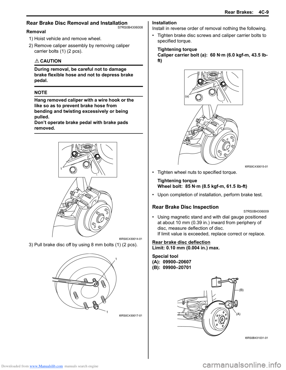
Removal1) Hoist vehicle and remove wheel.
2) Remove caliper assembly by removing caliper
carrier bolts (1) (2 pcs).
CAUTION!
During removal, be ca reful not to damage
brake flexible hose and not to depress brake
pedal.
NOTE
Hang removed caliper with a wire hook or the
like so as to prevent brake hose from
bending and twisting excessively or being
pulled.
Don’t operate brake pedal with brake pads
removed.
3) Pull brake disc off by using 8 mm bolts (1) (2 pcs). Installation
Install in reverse order of removal nothing the following.
• Tighten brake disc screws and caliper carrier bolts to
specified torque.
Tightening torque
Caliper carrier bolt (a): 60 N·m (6.0 kgf-m, 43.5 lb-
ft)
• Tighten wheel nuts to specified torque. Tightening torque
Wheel bolt: 85 N·m (8.5 kgf-m, 61.5 lb-ft)
• Upon completion of installation, perform brake test.
Rear Brake Disc InspectionS7RS0B4306009
• Using magnetic stand and with dial gauge positioned at about 10 mm (0.39 in.) inward from periphery of
disc, measure deflection of disc.
If limit value is exceeded, replace correct or replace.
Rear brake disc deflection
Limit: 0.10 mm (0.004 in.) max.
Special tool
(A): 09900–20607
(B): 09900–20701
1
I6RS0C430014-01
1 1I6RS0C430017-01
(a)
I6RS0C430015-01
(B)
(A)
I6RS0B431031-01
Page 835 of 1496

Downloaded from www.Manualslib.com manuals search engine Manual Transmission/Transaxle: 5B-21
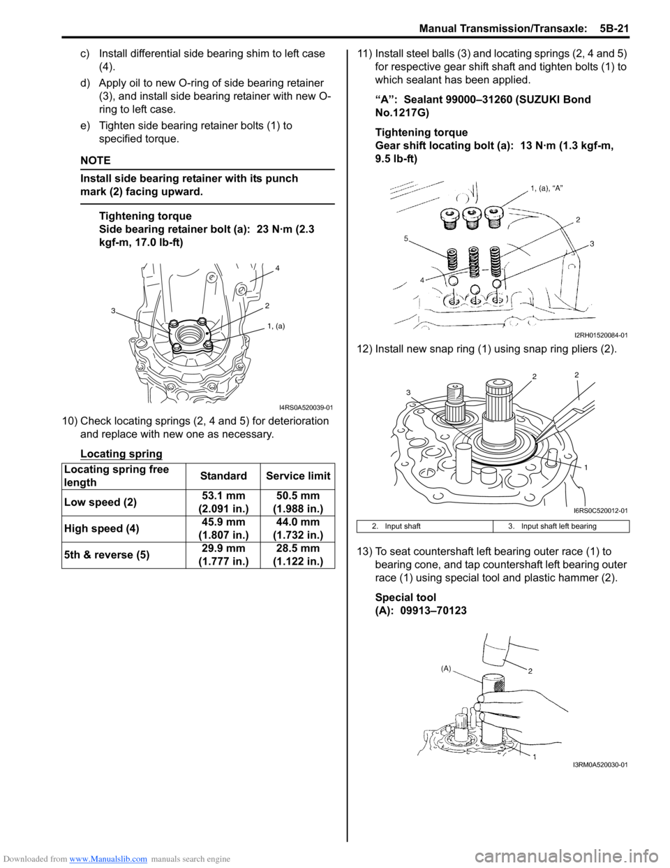
c) Install differential side bearing shim to left case (4).
d) Apply oil to new O-ring of side bearing retainer (3), and install side bea ring retainer with new O-
ring to left case.
e) Tighten side bearing retainer bolts (1) to specified torque.
NOTE
Install side bearing retainer with its punch
mark (2) facing upward.
Tightening torque
Side bearing retainer bolt (a): 23 N·m (2.3
kgf-m, 17.0 lb-ft)
10) Check locating springs (2, 4 and 5) for deterioration and replace with new one as necessary.
Locating spring
11) Install steel balls (3) and locating springs (2, 4 and 5) for respective gear shift shaft and tighten bolts (1) to
which sealant has been applied.
“A”: Sealant 99000–31260 (SUZUKI Bond
No.1217G)
Tightening torque
Gear shift locating bolt (a): 13 N·m (1.3 kgf-m,
9.5 lb-ft)
12) Install new snap ring (1) using snap ring pliers (2).
13) To seat countershaft left bearing outer race (1) to bearing cone, and tap countershaft left bearing outer
race (1) using special tool and plastic hammer (2).
Special tool
(A): 09913–70123
Locating spring free
length
Standard Service limit
Low speed (2) 53.1 mm
(2.091 in.) 50.5 mm
(1.988 in.)
High speed (4) 45.9 mm
(1.807 in.) 44.0 mm
(1.732 in.)
5th & reverse (5) 29.9 mm
(1.777 in.) 28.5 mm
(1.122 in.)
1, (a)
2
4
3
I4RS0A520039-01
2. Input shaft 3. Input shaft left bearing
I2RH01520084-01
1
2
2
3
I6RS0C520012-01
I3RM0A520030-01
Page 845 of 1496

Downloaded from www.Manualslib.com manuals search engine Manual Transmission/Transaxle: 5B-31
Synchronizer Parts InspectionS7RS0B5206021
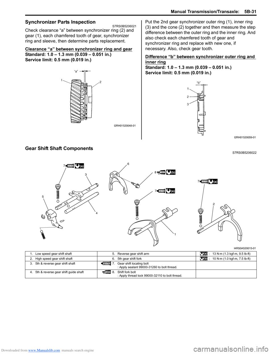
Check clearance “a” between synchronizer ring (2) and
gear (1), each chamfered tooth of gear, synchronizer
ring and sleeve, then determine parts replacement.
Clearance “a” between synchronizer ring and gear
Standard: 1.0 – 1.3 mm (0.039 – 0.051 in.)
Service limit: 0.5 mm (0.019 in.)Put the 2nd gear synchronizer outer ring (1), inner ring
(3) and the cone (2) together and then measure the step
difference between the outer ring and the inner ring. And
also check each chamfered tooth of gear and
synchronizer ring and replace with new one, if
necessary. Also, check gear tooth.
Difference “b” between synchronizer outer ring and
inner ring
Standard: 1.0 – 1.3 mm (0.039 – 0.051 in.)
Service limit: 0.5 mm (0.019 in.)
Gear Shift Shaft ComponentsS7RS0B5206022
I2RH01520048-01
I2RH01520059-01
5
3
4 6
1
2
8
7
77
(a)
(b)
(a)
(a)
I4RS0A520015-01
1. Low speed gear shift shaft
5. Reverse gear shift arm : 13 N⋅m (1.3 kgf-m, 9.5 lb-ft)
2. High speed gear shift shaft 6. 5th gear shift fork : 10 N⋅m (1.0 kgf-m, 7.5 lb-ft)
3. 5th & reverse gear shift shaft 7. Gear shift locating bolt
: Apply sealant 99000-31260 to bolt thread.
4. 5th & reverse gear shift guide shaft 8. Shift fork bolt
: Apply thread lock 99000-32110 to bolt thread.
Page 846 of 1496

Downloaded from www.Manualslib.com manuals search engine 5B-32 Manual Transmission/Transaxle:
5th and Reverse Gear Shift Shafts Disassembly
and Assembly
S7RS0B5206023
Disassembly
Disassemble component parts using special tool and
hammer.
Special tool
(A): 09922–85811
Assembly
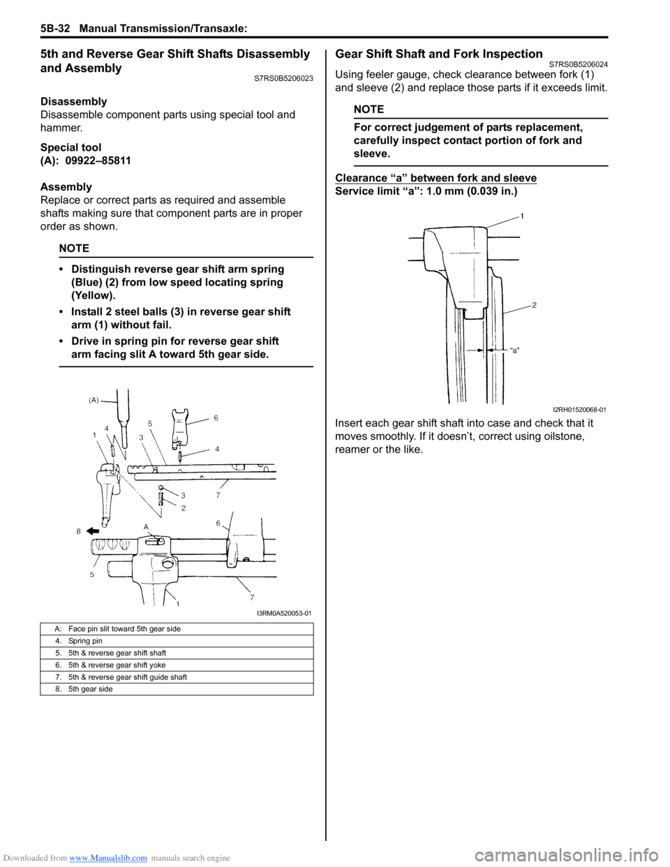
Replace or correct parts as required and assemble
shafts making sure that component parts are in proper
order as shown.
NOTE
• Distinguish reverse gear shift arm spring (Blue) (2) from low speed locating spring
(Yellow).
• Install 2 steel balls (3) in reverse gear shift arm (1) without fail.
• Drive in spring pin for reverse gear shift arm facing slit A toward 5th gear side.
Gear Shift Shaft and Fork InspectionS7RS0B5206024
Using feeler gauge, check clearance between fork (1)
and sleeve (2) and replace those parts if it exceeds limit.
NOTE
For correct judgement of parts replacement,
carefully inspect contact portion of fork and
sleeve.
Clearance “a” between fork and sleeve
Service limit “a”: 1.0 mm (0.039 in.)
Insert each gear shift shaft into case and check that it
moves smoothly. If it doesn’t, correct using oilstone,
reamer or the like.
A: Face pin slit toward 5th gear side
4. Spring pin
5. 5th & reverse gear shift shaft
6. 5th & reverse gear shift yoke
7. 5th & reverse gear shift guide shaft
8. 5th gear side
I3RM0A520053-01
I2RH01520068-01