2006 SUZUKI SWIFT Recirculation
[x] Cancel search: RecirculationPage 946 of 1496
Downloaded from www.Manualslib.com manuals search engine 7A-10 Heater and Ventilation:
Air Intake Control Actuator InspectionS7RS0B7106013
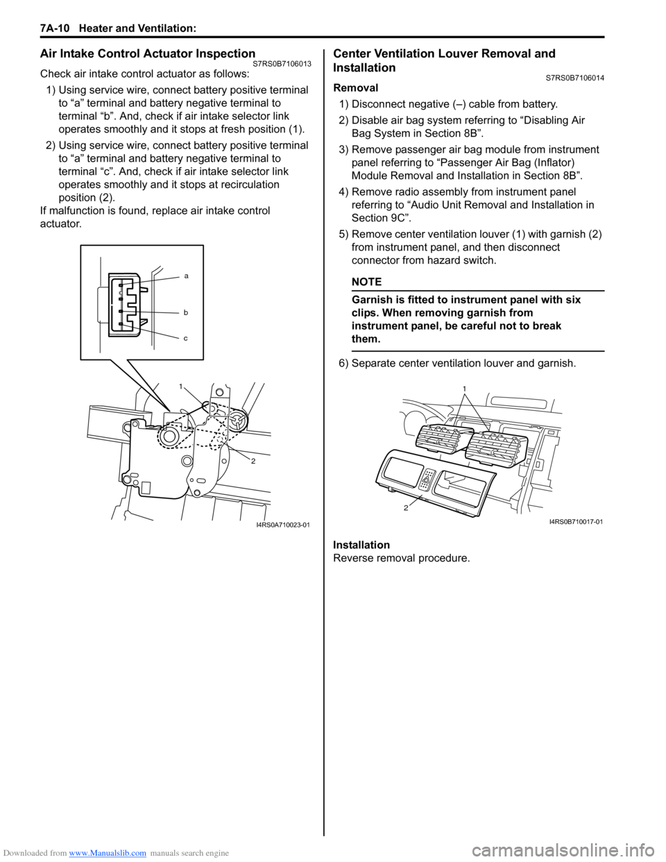
Check air intake control actuator as follows:1) Using service wire, connect battery positive terminal to “a” terminal and battery negative terminal to
terminal “b”. And, check if air intake selector link
operates smoothly and it st ops at fresh position (1).
2) Using service wire, connect battery positive terminal to “a” terminal and battery negative terminal to
terminal “c”. And, check if air intake selector link
operates smoothly and it stops at recirculation
position (2).
If malfunction is found, replace air intake control
actuator.
Center Ventilation Louver Removal and
Installation
S7RS0B7106014
Removal
1) Disconnect negative (–) cable from battery.
2) Disable air bag system referring to “Disabling Air Bag System in Section 8B”.
3) Remove passenger air bag module from instrument panel referring to “Passenger Air Bag (Inflator)
Module Removal and Installation in Section 8B”.
4) Remove radio assembly from instrument panel referring to “Audio Unit Re moval and Installation in
Section 9C”.
5) Remove center ventilation louver (1) with garnish (2) from instrument panel, and then disconnect
connector from hazard switch.
NOTE
Garnish is fitted to in strument panel with six
clips. When removing garnish from
instrument panel, be careful not to break
them.
6) Separate center ventilation louver and garnish.
Installation
Reverse removal procedure.
a
b
c
1
2
I4RS0A710023-01
1
2
I4RS0B710017-01
Page 953 of 1496
Downloaded from www.Manualslib.com manuals search engine Air Conditioning System: Manual Type 7B-5
Schematic and Routing Diagram
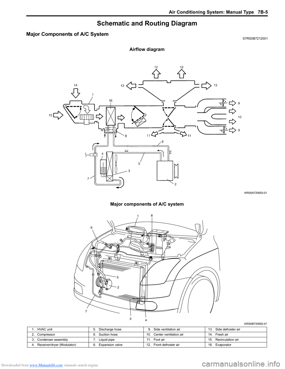
Major Components of A/C SystemS7RS0B7212001
Airflow diagram
Major components of A/C system
I4RS0A720003-01
7
2
34
1 8
6
5
I4RS0B720002-01
1. HVAC unit 5. Discharge hose9. Side ventilation air 13. Side defroster air
2. Compressor 6. Suction hose10. Center ventilation air 14. Fresh air
3. Condenser assembly 7. Liquid pipe11. Foot air 15. Recirculation air
4. Receiver/dryer (Modulator) 8. Expansion valve12. Front defroster air 16. Evaporator
Page 959 of 1496
Downloaded from www.Manualslib.com manuals search engine Air Conditioning System: Manual Type 7B-11
5) Warm up engine to the normal operating temperature and keep it at the specified idle speed.
6) Turn A/C switch ON, set blower speed selector at maximum speed position, temperature selector at
maximum cold position, airflow selector at face
position, and air intake switch at recirculation
position. (Confirm that A/C compressor and
condenser fans are working.)
7) Wait for ten minutes to stabilize the A/C operation.
8) Open front windows, front doors and engine hood.
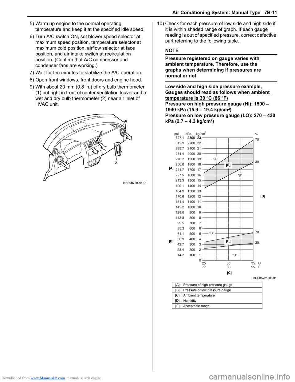
9) With about 20 mm (0.8 in.) of dry bulb thermometer
(1) put right in front of center ventilation louver and a
wet and dry bulb thermometer (2) near air inlet of
HVAC unit. 10) Check for each pressure of low side and high side if
it is within shaded range of graph. If each gauge
reading is out of specified pressure, correct defective
part referring to the following table.
NOTE
Pressure registered on gauge varies with
ambient temperature. Therefore, use the
graphs when determining if pressures are
normal or not.
Low side and high side pressure example,
Gauges should read as follows when ambient
temperature is 30 °C (86 °F)
Pressure on high pressure gauge (HI): 1590 –
1940 kPa (15.9 – 19.4 kg/cm2)
Pressure on low pressure gauge (LO): 270 – 430
kPa (2.7 – 4.3 kg/cm
2)
2
1
I4RS0B720004-01
[A]: Pressure of high pressure gauge
[B]: Pressure of low pressure gauge
[C]: Ambient temperature
[D]: Humidity [E]: Acceptable range
22
312.9 2200
0 1
2 3 30 70 30 70 %
4 5 6 7 8 9
10
11 12 13 14 15
16 17
18
19 21
298.7 2100
20
14.2 28.4 42.7 56.9 71.1 85.3 99.5
113.8 128.0 142.2
151.4
170.6
184.9 199.1
213.3 227.5
241.7
256.0
270.2
284.4
100 200 300 400 500 600 700 800 900
1000 1100 1200
1300
1400 1500 1600
1700 1800
1900
2000
25 30 35
77 86 95
psi kPa kg/cm
2
C
F
“A”
“B”
“C”
“D”
23
2300
327.1
[A]
[B]
[C][D][E]
[E]
I7RS0A721006-01
Page 984 of 1496
Downloaded from www.Manualslib.com manuals search engine 7B-36 Air Conditioning System: Automatic Type
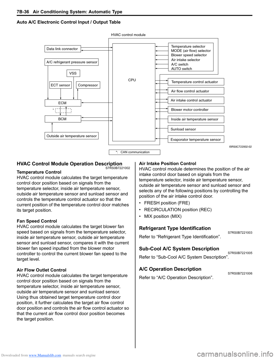
Auto A/C Electronic Control Input / Output Table
HVAC Control Module Operation DescriptionS7RS0B7221002
Temperature Control
HVAC control module calculates the target temperature
control door position based on signals from the
temperature selector, inside air temperature sensor,
outside air temperature sensor and sunload sensor and
controls the temperature control actuator so that the
current position of the temperature control door matches
its target position.
Fan Speed Control
HVAC control module calculates the target blower fan
speed based on signals from the temperature selector,
inside air temperature sensor, outside air temperature
sensor and sunload sensor, compares it with the current
blower fan speed inputted from the blower motor
controller to control the current blower fan speed to the
target level.
Air Flow Outlet Control
HVAC control module calculates the target temperature
control door position based on signals from the
temperature selector, inside air temperature sensor,
outside air temperature sensor and sunload sensor.
Using thus obtained target temperature control door
position, it further calculates the target air flow control
door position and controls the ai r flow control actuator so
that the current air flow c ontrol door position becomes
the target position. Air Intake Position Control
HVAC control module determines the position of the air
intake control door based on signals from the
temperature selector, inside air temperature sensor,
outside air temperature sensor and sunload sensor and
selects any of the following positions by controlling the
position of the air intake control door.
• FRESH position (FRE)
• RECIRCULATION position (REC)
• MIX position (MIX)
Refrigerant Type IdentificationS7RS0B7221003
Refer to “Refrigerant Type Identification”.
Sub-Cool A/C System DescriptionS7RS0B7221005
Refer to “Sub-Cool A/C System Description”.
A/C Operation DescriptionS7RS0B7221006
Refer to “A/C Operation Description”.
Sunload sensor
Outside air temperature sensor Evaporator temperature sensor
A/C refrigerant pressure sensor
Temperature selector
MODE (air flow) selector
Blower speed selector
Air intake selector
AUTO switch
A/C switch
Compressor
Blower motor controller
Temperature control actuator
Air flow control actuator
Air intake control actuator
BCM
ECM
Data link connector
HVAC control module
CPU
ECT sensor
Inside air temperature sensor
VSS
*
I5RS0C722002-02
*: CAN communication
Page 994 of 1496
Downloaded from www.Manualslib.com manuals search engine 7B-46 Air Conditioning System: Automatic Type
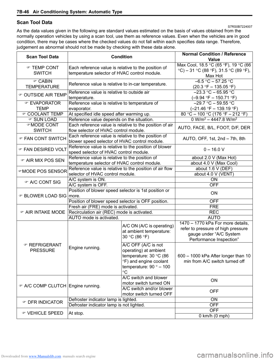
Scan Tool DataS7RS0B7224007
As the data values given in the following are standard values estimated on the basis of values obtained from the
normally operation vehicles by using a scan tool, use them as reference values. Even when the vehicles are in good
condition, there may be cases where the checked values do not fall within each specifies data range. Therefore,
judgement as abnormal should not be ma de by checking with these data alone.
Scan Tool Data Condition Normal Condition / Reference
Va l u e
�) TEMP CONT
SWITCH Each reference value is relative to the position of
temperature selector of HVAC control module. Max Cool, 18.5
°C (65 ° F), 19 °C (66
° C) – 31 °C (88 °F), 31.5 °C (89 °F),
Max Hot
�) CABIN
TEMPERATURE Reference value is relative to in-car temperature. –6.5
°C – 57.25 ° C
(20.3 °F – 135.05 °F)
�) OUTSIDE AIR TEMP Reference value is relative to outside air
temperature. –23.3
°C – 65.95 °C
(–9.94 °F – 150.71 °F)
�) EVAPORATOR
TEMP Reference value is relative to temperature of
evaporator. –29.7
°C – 59.55 °C
(–21.46 °F – 139.19 °F)
�) COOLANT TEMP At specified id le speed after warming up. 80 °C – 100 °C (176 ° F – 212 ° F)
�) SUN LOAD Reference value depends on the situation. 0 W/m
2 – 4447.8 W/m2
�)MODE CONT
SWITCH Each reference value is relative to the position of air
flow selector of HVAC control module.
AUTO, FACE, B/L, FOOT, D/F, DER
�) FAN CONT SWITCH Each reference value is relative to the position of
blower speed selector of HVAC control module. AUTO, OFF, 1st, 2nd – 7th, 8th
�) FAN DESIRED VOLT Reference value is relative to the position of blower
speed selector of HVAC control module. 0 – 16.0 V
�) AIR MIX POS SEN Reference value is relative to the position of
temperature selector of HVAC control module. about 2.0 V (Max Hot)
about 4.0 V (Max Cool)
�) MODE POS SENSOR Reference value is relative to the position of air flow
selector of HVAC control module. about 1.6 V (DEF)
about 4.0 V (VENT)
�) A/C CONT SIG A/C system is ON. ON
A/C system is OFF. OFF
�) BLOWER LOAD SIG Position of blower speed selector is 1st position or
more.
ON
Position of blower speed selector is OFF position. OFF
�) AIR INTAKE MODE Fresh air (FRE) mode is activated. FRE
Recirculation air (REC) mode is activated. REC
AUTO mode is activated. AUTO
�) REFRIGERANT
PRESSURE Engine running. A/C ON (A/C is operating)
at ambient temperature:
30
°C (86 °F) 1470 – 1770 kPa For more details,
refer to pressure of high pressure
gauge under “A/C System Performance Inspection”
A/C OFF (A/C is not
operating) at ambient
temperature: 30 °C (86
° F) and engine coolant
temperature: 90 ° – 100
° C 600 – 1000 kPa After longer than 10
min from A/C switch turned off
�) A/C COMP CLUTCH Engine running. A/C switch and blower
motor switch turned ON
ON
A/C switch and/or blower
motor switch turned OFF OFF
�) DFR INDICATOR Defroster indicator
lamp is lighted. ON
Defroster indicator la mp is not lighted. OFF
�) VEHICLE SPEED At stop. OFF
0 km/h (0 mph)
Page 1016 of 1496
Downloaded from www.Manualslib.com manuals search engine 7B-68 Air Conditioning System: Automatic Type
G51-8 BLU/REDBlower motor control
voltage feedback 10 – 14 V Ignition switch turned ON, blower speed selector OFF
About 8.5 V Ignition switch turned ON, blower speed selector 1st
position
About 6.5 V Ignition switch turned ON, blower speed selector 2nd
position
About 5.5 V Ignition switch turned ON, blower speed selector 3rd
position
About 4.0 V Ignition switch turned ON, blower speed selector 4th
position
About 3.0 V Ignition switch turned ON, blower speed selector 5th
position
About 2.0 V Ignition switch turned ON, blower speed selector 6th
position
About 1.0 V Ignition switch turned ON, blower speed selector 7th
position
Below 1.0 V Ignition switch turned ON, blower speed selector HIGH
position
G51-9 GRY Blower motor controller 0 – 1 V
Ignition switch turned ON, blower speed selector OFF
position
2 – 3 V Ignition switch turned ON, blower speed selector
between 1st and HIGH position
G51-10 BLK/RED Rear defogger indicator 0 – 1 V Ignition switch turned ON, rear defogger switch OFF
10 – 14 V Ignition switch turned ON, rear defogger switch ON
G51-11 RED/YEL Illumination switch 0 – 1 V Ignition switch turned ON, lighting switch OFF position
10 – 14 V Ignition switch turned ON, lighting switch ON position
G51-12 BLK/YEL Illumination ground 0 – 1 V Full-time
G51-13 — — — —
G51-14 — — — —
G51-15 RED Air intake actuator
(RECIRCULATION AIR) 0 – 1 VIgnition switch turned ON, air intake selector is
recirculation air mode or air intake actuator is working
in operation to recirculation air position or fresh air
position.
10 – 14 V Ignition switch turned ON, ai
r intake selector is fresh
air mode (air intake actuator fresh air position).
G51-16 GRN/RED Air intake actuator
(MIX AIR) 10 – 14 V
Ignition switch turned ON, air intake actuator is
recirculation air or fresh air position.
0 – 1 V Ignition switch turned ON, air intake actuator is mix air
position or air intake actuator is working in operation to
recirculation air position or fresh air position.
G51-17 GRN Air intake actuator
(FRESH AIR) 0 – 1 V
Ignition switch turned ON, ai
r intake selector is fresh
air mode or air intake actuator is working in operation
to recirculation air position or fresh air position.
10 – 14 V Ignition switch turned ON, air intake selector is
recirculation air mode (air intake actuator recirculation
air position).
G51-18 GRN/WHT A/C switch signal Refer to “Inspe ction of BCM and its Circuits in Section 10B”
G51-19 BLU/WHT Electric load signal for
blower motor 10 – 14 V
Ignition switch turned ON, blower speed selector OFF
or between 1st and 5th position
0 – 2 V Ignition switch turned ON, blower speed selector
between 6th and HIGH position
G51-20 BRN Rear defogger switch 0 – 1 V
Ignition switch turned ON, rear defogger switch ON
(rear defogger switch is kept in push) position
4 – 6 V Ignition switch turned ON, rear defogger switch OFF
position
Terminal Wire Color Circuit
Normal
Vo l ta g e Condition