2006 SUZUKI SWIFT roller
[x] Cancel search: rollerPage 14 of 1496
Downloaded from www.Manualslib.com manuals search engine 00-9 Precautions:
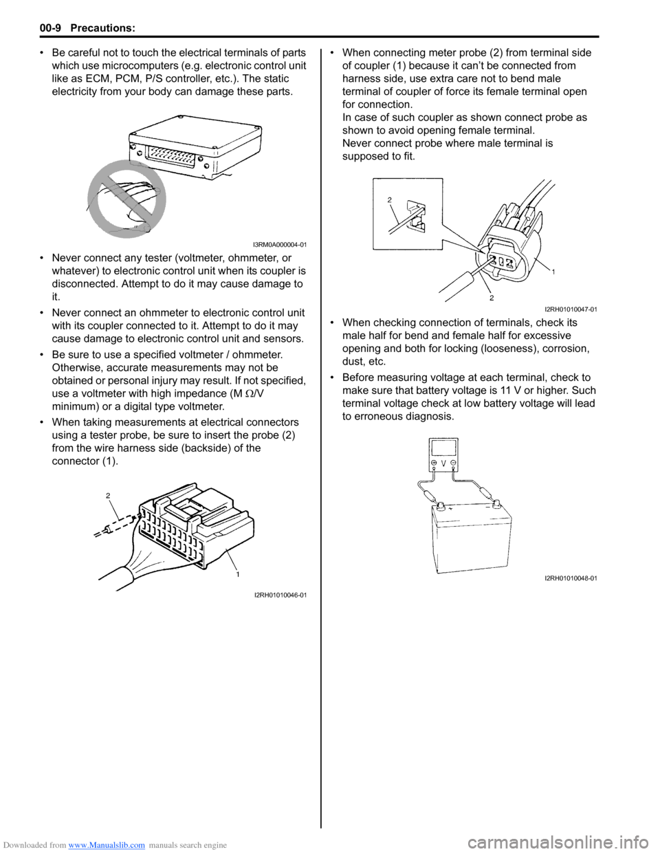
• Be careful not to touch the electrical terminals of parts which use microcomputers (e.g. electronic control unit
like as ECM, PCM, P/S controller, etc.). The static
electricity from your body can damage these parts.
• Never connect any tester (voltmeter, ohmmeter, or whatever) to electronic control unit when its coupler is
disconnected. Attempt to do it may cause damage to
it.
• Never connect an ohmmeter to electronic control unit with its coupler connected to it. Attempt to do it may
cause damage to electronic control unit and sensors.
• Be sure to use a specified voltmeter / ohmmeter. Otherwise, accurate measurements may not be
obtained or personal injury ma y result. If not specified,
use a voltmeter with high impedance (M Ω/V
minimum) or a digital type voltmeter.
• When taking measurements at electrical connectors using a tester probe, be sure to insert the probe (2)
from the wire harness side (backside) of the
connector (1). • When connecting meter probe (2) from terminal side
of coupler (1) because it can’t be connected from
harness side, use extra care not to bend male
terminal of coupler of force its female terminal open
for connection.
In case of such coupler as shown connect probe as
shown to avoid opening female terminal.
Never connect probe where male terminal is
supposed to fit.
• When checking connection of terminals, check its
male half for bend and female half for excessive
opening and both for locking (looseness), corrosion,
dust, etc.
• Before measuring voltage at each terminal, check to make sure that battery voltage is 11 V or higher. Such
terminal voltage check at lo w battery voltage will lead
to erroneous diagnosis.
I3RM0A000004-01
I2RH01010046-01
I2RH01010047-01
I2RH01010048-01
Page 22 of 1496
Downloaded from www.Manualslib.com manuals search engine 0A-1 General Information:
General Information
General Information
General Description
AbbreviationsS7RS0B0101001
A:
ABDC: After Bottom Dead Center
ABS: Anti-lock Brake System
AC: Alternating Current
A/C: Air Conditioning
A-ELR: Automatic-Emergency Locking Retractor
A/F: Air Fuel Mixture Ratio
ALR: Automatic Locking Retractor
API: American Petroleum Institute
APP sensor: Accelerator Pedal Position Sensor
A/T: Automatic Transmission , Automatic Transaxle
AT D C : After Top Dead Center
ATF: Automatic Transmission Fluid, Automatic
Transaxle Fluid
B:
B+: Battery Positive Voltage
BBDC: Before Bottom Dead Center
BCM: Body Electrical Control Module
BDC: Bottom Dead Center
BTDC: Before Top Dead Center
C:
CAN: Controller Area Network
CKT: Circuit
CKP Sensor: Crankshaft Position Sensor
CMP Sensor: Camshaft Position Sensor
CO: Carbon Monoxide
CPP Switch: Clutch Pedal Position Switch (Clutch
Switch, Clutch Start Switch)
CPU: Central Processing Unit
CRS: Child Restraint System
D:
DC: Direct Current
DLC: Data Link Connector (Assembly Line Diag. Link,
ALDL, Serial Data Link, SDL)
DOHC: Double Over Head Camshaft
DOJ: Double Offset Joint
DRL: Daytime Running Light
DTC: Diagnostic Trouble Code (Diagnostic Code)
E:
EBCM: Electronic Brake Cont rol Module, ABS Control
Module
EBD: Electronic Brake Force Distribution
ECM: Engine Control Module
ECT Sensor: Engine Coolant Temperature Sensor (Water Temp. Sensor, WTS)
EFE Heater: Early Fuel Evaporation Heater (Positive
Temperature Coefficient, PTC Heater)
EGR: Exhaust Gas Recirculation
EGRT Sensor: EGR Temperature Sensor (Recirculated
Exhaust Gas Temp. Sensor, REGTS)
ELR: Emergency Locking Retractor
ESP ®: Electronic Stability Program
EPS: Electronic Power Steering
EVAP: Evaporative Emission EVAP Canister:
Evaporative Emission Canister
(Charcoal Canister)
F:
4WD: 4 Wheel
Drive
G:
GEN: Generator
GND: Ground
GPS: Global Positioning System
H:
HVAC: Heating, Ventilating and Air Conditioning
HC: Hydrocarbons
HO2S: Heated Oxygen Sensor
I:
IAC Valve: Idle Air Control Valve (Idle Speed Control
Solenoid Valve, ISC Solenoid Valve)
IAT Sensor: Intake Air Temperature Sensor (Air
temperature Sensor, ATS)
ICM: Immobilizer Control Module
IG: Ignition
ISC Actuator: Idle Speed Control Actuator
L:
LH: Left Hand
LHD: Left Hand Drive Vehicle
LSPV: Load Sensing Proportioning Valve
M:
MAF Sensor: Mass Air Flow Sensor (Air Flow Sensor, AFS, Air Flow Meter, AFM)
MAP Sensor: Manifold Absolute Pressure Sensor
(Pressure Sensor, PS)
Max: Maximum
MFI: Multiport Fuel Injection (Mu ltipoint Fuel Injection)
Min: Minimum
MIL: Malfunction Indicator Lamp (“SERVICE ENGINE
SOON” Light)
M/T: Manual Transmission, Manual Transaxle
N:
NOx: Nitrogen Oxides
O:
OBD: On-Board Diagnostic System (Self-Diagnosis
Function)
O/D: Overdrive
OHC: Over Head Camshaft
O2S: Oxygen Sensor
P:
PCM: Powertrain Control Module
PCV: Positive Crankcase Ventilation
PNP: Park / Neutral Position
P/S: Power Steering
PSP Switch: Power Steering Pressure Switch (P/S
Pressure Switch)
R:
RH: Right Hand
RHD: Right Hand Drive Vehicle
S:
SAE: Society of Automotive Engineers
Page 23 of 1496
Downloaded from www.Manualslib.com manuals search engine General Information: 0A-2
SAS: Steering Angle Sensor
SDM: Sensing and Diagnostic Module (Air Bag Controller, Air bag Control Module)
SDT: Smart Diagnostic Tester
SFI: Sequential Multipor t Fuel Injection
SOHC: Single Over Head Camshaft
T:
TBI: Throttle Body Fuel Injection (Single-Point Fuel
Injection, SPI)
TCC: Torque Converter Clutch
TCM: Transmission Control Module (A/T Controller, A/T
Control Module)
TDC: Top Dead Center
TP Sensor: Throttle Position Sensor TVV:
Thermal Vacuum Valve (Thermal Vacuum
Switching Valve, TVSV, Bi metal Vacuum Switching
Valve, BVSV)
TWC: Three Way Catalytic Converter (Three Way
Catalyst)
2WD: 2 Wheel Drive
U:
USB: Universal Serial Bus
V:
VIN: Vehicle Identification Number
VSS: Vehicle Speed Sensor
VVT: Variable Valve Timing (Camshaft Position Control)
W:
WU-OC: Warm Up Oxidation Catalytic Converter
WU-TWC: Warm Up Three Way Catalytic Converter
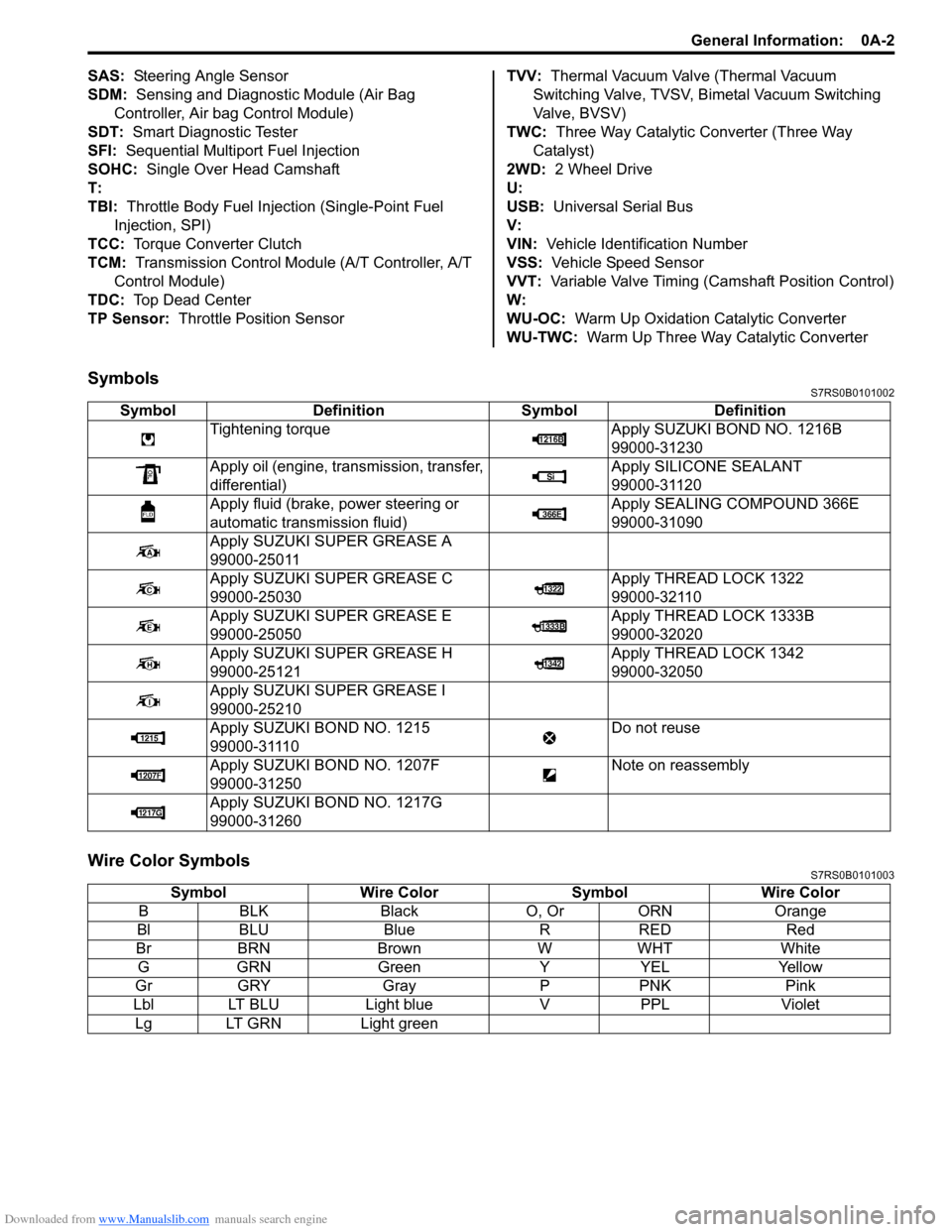
SymbolsS7RS0B0101002
Wire Color SymbolsS7RS0B0101003
Symbol Definition SymbolDefinition
Tightening torque Apply SUZUKI BOND NO. 1216B
99000-31230
Apply oil (engine, transmission, transfer,
differential) Apply SILICONE SEALANT
99000-31120
Apply fluid (brake, power steering or
automatic transmission fluid) Apply SEALING COMPOUND 366E
99000-31090
Apply SUZUKI SUPER GREASE A
99000-25011
Apply SUZUKI SUPER GREASE C
99000-25030 Apply THREAD LOCK 1322
99000-32110
Apply SUZUKI SUPER GREASE E
99000-25050 Apply THREAD LOCK 1333B
99000-32020
Apply SUZUKI SUPER GREASE H
99000-25121 Apply THREAD LOCK 1342
99000-32050
Apply SUZUKI SUPER GREASE I
99000-25210
Apply SUZUKI BOND NO. 1215
99000-31110 Do not reuse
Apply SUZUKI BO ND NO. 1207F
99000-31250 Note on reassembly
Apply SUZUKI BO ND NO. 1217G
99000-31260
Symbol Wire Color SymbolWire Color
B BLK Black O, Or ORN Orange
Bl BLU Blue RRED Red
Br BRN Brown WWHT White
G GRN Green YYEL Yellow
Gr GRY Gray PPNK Pink
Lbl LT BLU Light blueVPPL Violet
Lg LT GRN Light green
Page 52 of 1496
Downloaded from www.Manualslib.com manuals search engine 1A-2 Engine General Information and Diagnosis:
• Be sure to read “Precautions for Electrical Circuit Service in Section 00” befo re inspection and observe
what is written there.
• ECM replacement: When substituting a known-good ECM, check for the
following conditions. Neglec ting this check may cause
damage to a known-good ECM.
– Resistance value of all relays, actuators is as specified respectively.
– MAP sensor, A/C refrigerant pressure sensor and TP sensor are in good condition and none of power
circuits of these sensors is shorted to ground.
• Communication of ECM, BCM, ABS/ESP ® control
module, combination meter, keyless start control
module, steering angle sensor (ESP ® model) and
TCM (A/T model), is esta blished by CAN (Controller
Area Network). (For more detail of CAN
communication for ECM, refer to “CAN
Communication System Description”). Therefore,
handle CAN communication line with care referring to
“Precaution for CAN Communication System in
Section 00”.
• Immobilizer transponder code registration after
replacing ECM
When ECM is replaced with new one or with another
one, make sure to register immobilizer transponder
code to ECM correctly according to “Procedure after
ECM Replacement in Section 10C”.Precautions of ECM Circuit InspectionS7RS0B1100003
• ECM connectors are waterproofed. Each terminal of the ECM connectors is sealed up with the grommet.
Therefore, when measuring ci rcuit voltage, resistance
and/or pulse signal at ECM connector, do not insert
the tester’s probe into th e sealed terminal at the
harness side. When measuring circuit voltage,
resistance and/or pulse signal at ECM connector,
connect the special tool to the ECM connectors. And,
insert the tester’s probe into the special tool’s
connectors at the harness side, and then measure
voltage, resistance and/or pulse signal. Or, ECM and
its circuits may be damaged by water.
• Wire colors of the special tool’s connectors are different from the ones of the ECM connectors.
However, the circuit arrangement of the special tool’s
connectors is same as the one of the ECM
connectors. Therefore, measure circuit voltage and
resistance by identifying the terminal location subject
to the measurement.
Precautions of Electric Throttle Body System
Calibration
S7RS0B1100004
After performing one of works described below, it is
necessary to re-register the completely closed throttle
valve reference position stored in memory of ECM. (For
detailed information, refer to “Description of Electric
Throttle Body System Calibration”.) For the procedure to
register such data in ECM, refer to “Electric Throttle
Body System Calibration in Section 1C”.
• To shut off backup power of ECM for such purposes of battery replacement or “DOME” fuse removal
• To erase DTCs P0122, P01 23, P0222, P0223, P2101,
P2102, P2103, P2111, P2112, P2113, P2119, P2123,
P2127, P2128, P2135 and/or P2138
• To replace ECM
• To replace throttle body and/or accelerator pedal position (APP) sensor assembly
General Description
Statement on Cleanliness and CareS7RS0B1101001
An automobile engine is a combination of many
machined, honed, polished and lapped surfaces with
tolerances that are measured in the thousands of an
millimeter (ten thous ands of an inch).
Accordingly, when any internal engine parts are
serviced, care and cleanliness are important.
It should be understood that proper cleaning and
protection of machined surfaces and friction areas is part
of the repair procedure. This is considered standard
shop practice even if not specifically stated.
• A liberal coating of engine oil should be applied to friction areas during assembly to protect and lubricate
the surfaces on initial operation. • Whenever valve train components, pistons, piston
rings, connecting rods, rod bearings, and crankshaft
journal bearings are removed for service, they should
be retained in order.
At the time of installation, they should be installed in
the same locations and with the same mating
surfaces as when removed.
• Battery cables should be disconnected before any major work is performed on the engine.
Failure to disconnect cables may result in damage to
wire harness or other electrical parts.
Page 57 of 1496
Downloaded from www.Manualslib.com manuals search engine Engine General Information and Diagnosis: 1A-7
CAN Communication System DescriptionS7RS0B1101005
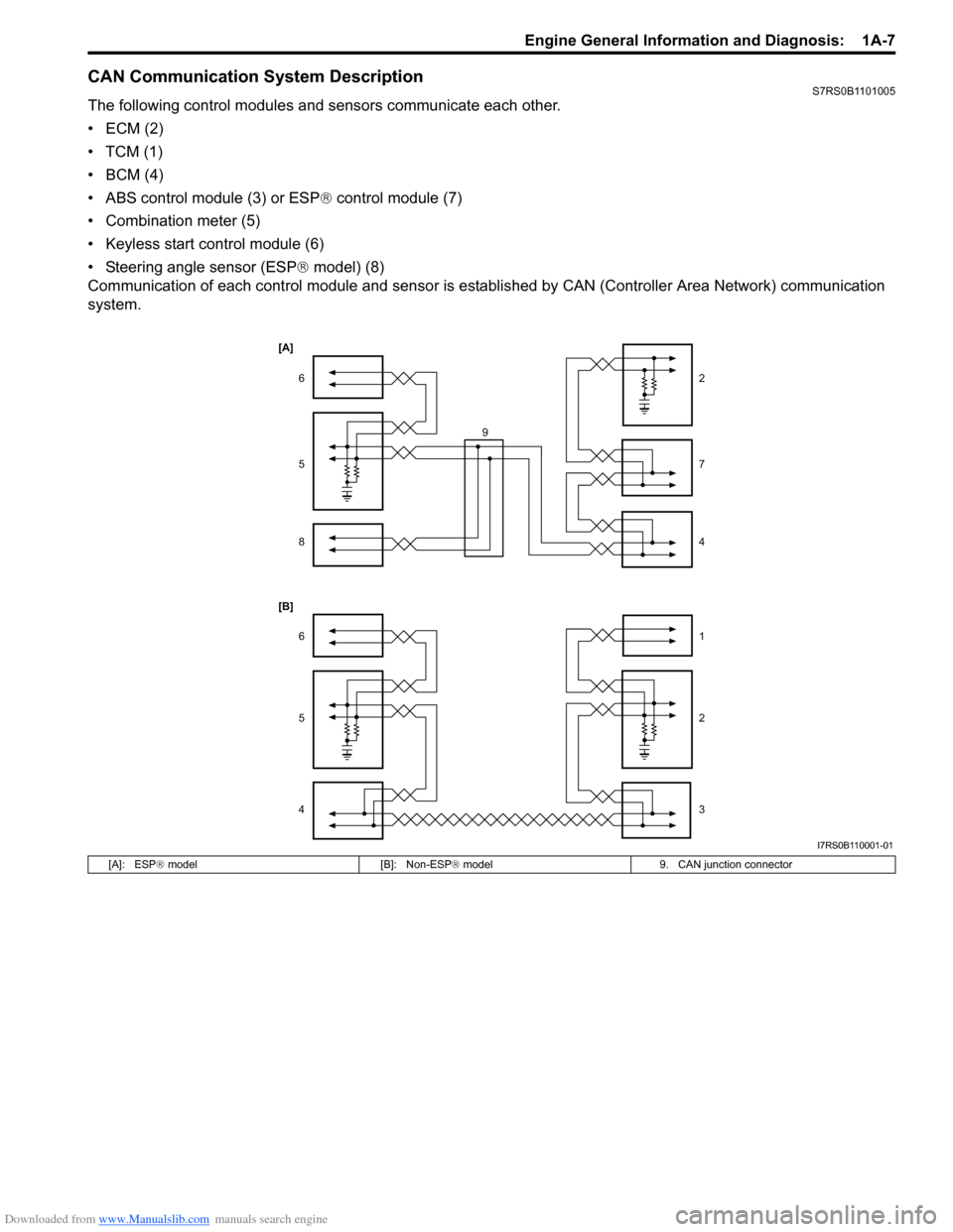
The following control modules and sensors communicate each other.
•ECM (2)
•TCM (1)
•BCM (4)
• ABS control module (3) or ESP® control module (7)
• Combination meter (5)
• Keyless start control module (6)
• Steering angle sensor (ESP ® model) (8)
Communication of each control module and sensor is es tablished by CAN (Controller Area Network) communication
system.
1
2
3
6
5
4
2
7
4
6
5
8
9
[A]
[B]
I7RS0B110001-01
[A]: ESP
® model [B]: Non-ESP ® model 9. CAN junction connector
Page 62 of 1496
Downloaded from www.Manualslib.com manuals search engine 1A-12 Engine General Information and Diagnosis:
Electronic Control System DescriptionS7RS0B1101011
The electronic control system consists of 1) various sensors which detect the state of engine and driving conditions, 2)
ECM which controls various devices ac cording to the signals from the sensors and 3) various controlled devices.
Functionally, it is divided into the following sub systems:
• Fuel injection control system
• Ignition control system
• Electric throttle body control system
• Fuel pump control system
• Radiator cooling fan control system
• Evaporative emission control system
• EGR system
• Oxygen sensor heater control system
• A/C control system (A/C model)
• Camshaft position control system
• Immobilizer control system
• Generator control system
• Controller (computer) communication system
Especially, ECM, BCM, combination meter, TCM (A/T model), ABS/ESP ® control module, steering angle sensor
(ESP® model) and keyless start control module (if equipped) intercommunicate by means of CAN communication.
Page 65 of 1496
![SUZUKI SWIFT 2006 2.G Service Workshop Manual Downloaded from www.Manualslib.com manuals search engine Engine General Information and Diagnosis: 1A-15
Terminal Arrangement of ECM Coupler (Viewed from Harness Side)
[A]: Manual A/C model24. ABS / SUZUKI SWIFT 2006 2.G Service Workshop Manual Downloaded from www.Manualslib.com manuals search engine Engine General Information and Diagnosis: 1A-15
Terminal Arrangement of ECM Coupler (Viewed from Harness Side)
[A]: Manual A/C model24. ABS /](/manual-img/20/7607/w960_7607-64.png)
Downloaded from www.Manualslib.com manuals search engine Engine General Information and Diagnosis: 1A-15
Terminal Arrangement of ECM Coupler (Viewed from Harness Side)
[A]: Manual A/C model24. ABS / ESP® control module 49. Radiator cooling fan motor
[B]: Auto A/C model 25. TCM 50. “RDTR FAN” fuse
1. ECM 26. To other control module connected CAN 51. A/C compressor relay
2. APP sensor assembly 27. Generator 52. Magnet clutch of compressor (A/C model)
3. Shield wire 28. Electric load current sensor (if equipped) 53. “A/C CPRSR” fuse
4. CMP sensor 29. Brake light 54. Ignition coil assembly (for No.1 and No.4 spark
plugs)
5. CKP sensor 30. Brake light switch 55. Ignition coil assembly (for No.2 and No.3 spark
plugs)
6. MAF and IAT sensor 31. Diagnosis connector (Hong Kong model) 56. P/S control module
7. MAP sensor 32. Throttle actuator control relay 57. “RADIO” fuse
8. ECT sensor 33. “THR MOT” fuse 58. Main relay
9. A/C refrigerant pressure sensor 34. Throttle throttle body assembly 59. “IG COIL” fuse
10. A/C evaporator outlet air temp. sensor (Manual A/C model) 35. Throttle actuator
60. Ignition switch
11. HO2S-1 36. TP sensor 61. “IG ACC” fuse
12. HO2S-2 37. Injector No.1 62. “FI” fuse
13. Knock sensor 38. Injector No.2 63. Starting motor control relay
14. Blower motor relay 39. Injector No.3 64. “ST SIG” fuse
15. Blower motor 40. Injector No.4 65. “ST MOT” fuse
16. Blower motor resistor 41. EVAP canister purge valve66. Transmission range switch (A/T model) or CPP
switch (Hong Kong model with M/T)
17. Blower speed selector 42. EGR valve 67. Starting motor
18. A/C switch 43. Oil control valve (Camshaft position
control) (VVT model) 68. Immobilizer coil antenna
19. Blower motor controller 44. Fuel pump relay 69. Main fuse box
20. HVAC control module 45. Fuel pump 70. Battery
21. Data link connector (DLC) 46. Radiator cooling fan motor relay No.1 71. Barometric pressure sensor
22. To other control module connected with DLC 47. Radiator cooling fan motor relay No.2
72. Engine ground
23. BCM 48. Radiator cooling fan motor relay No.3 73. Body ground
E23 C37
34
1819
567
1011
17
20
47 46
495051
2122
52 16
25 9
24
14
29
55
57 54 53
59
60 58 2
262728
15
30
56 4832 31
34353637
40
42 39 38
44
45 43 41 331
1213
238
34
1819
567
1011
17
20
47 46
495051
2122
52 16
25 9
24
14
29
55
57 54 53
59
60 58 2
262728
15
30
56 4832 31
34353637
40
42 39 38
44
45 43 41 331
1213
238
I4RS0A110008-01
Page 540 of 1496
Downloaded from www.Manualslib.com manuals search engine 4E-1 ABS:
Brakes
ABS
Precautions
Precautions in Diagnosing TroublesS7RS0B4500001
To ensure that the trouble diagnosis is done accurately
and smoothly, observe the following and follow “ABS
Check”.
• Diagnostic information stored in ABS cont rol module
memory can be cleared as well as checked by using
SUZUKI scan tool. Before us ing scan tool, read its
Operator’s (Instruction) Manual carefully to have good
understanding as to what functions are available and
how to use it.
• If the vehicles was operated in any of the following ways, ABS warning light may light momentarily but
this does not indicate anything abnormal in ABS.
– The vehicle was driven with parking brake pulled.
– The vehicle was driven with brake dragging.
– The vehicle was stuck in mud, sand, etc.
– Wheel spin occurred while driving.
– Wheel(s) was rotated while the vehicle was jacked up.
• Be sure to read “Precautions for Electrical Circuit Service in Section 00” befo re inspection and observe
what is written there.
• Be sure to use the trouble diagnosis procedure as described in “ABS Check”. Failure to follow it may
result in incorrect diagnosis. (Some other diagnosis
trouble code may be stored by mistake in the memory
of ABS control module during inspection.)
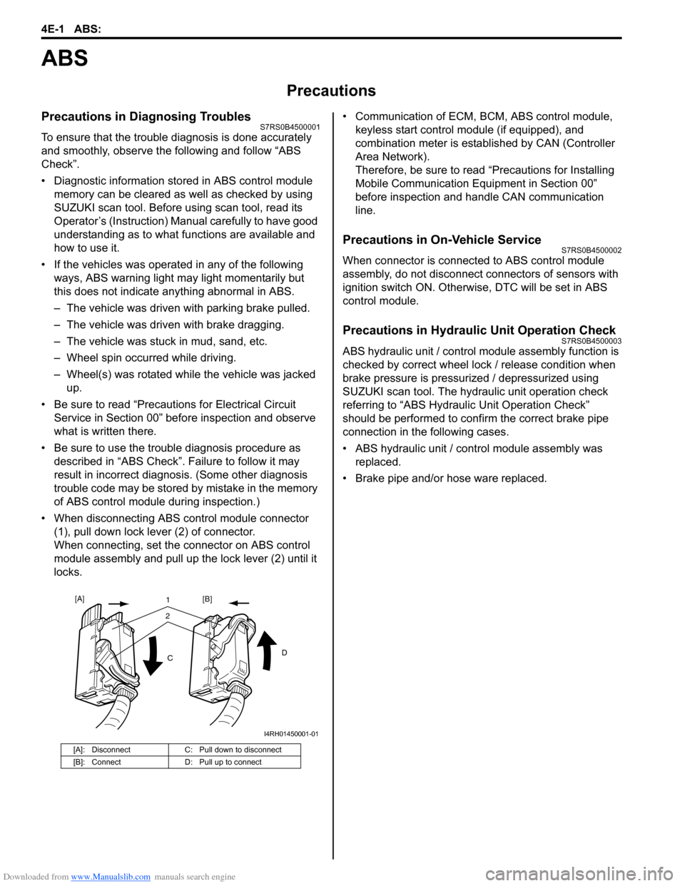
• When disconnecting ABS co ntrol module connector
(1), pull down lock lever (2) of connector.
When connecting, set the connector on ABS control
module assembly and pull up the lock lever (2) until it
locks. • Communication of ECM,
BCM, ABS control module,
keyless start control module (if equipped), and
combination meter is established by CAN (Controller
Area Network).
Therefore, be sure to read “Precautions for Installing
Mobile Communication Equipment in Section 00”
before inspection and handle CAN communication
line.
Precautions in On-Vehicle ServiceS7RS0B4500002
When connector is connected to ABS control module
assembly, do not disconnect connectors of sensors with
ignition switch ON. Otherwise, DTC will be set in ABS
control module.
Precautions in Hydraulic Unit Operation CheckS7RS0B4500003
ABS hydraulic unit / control module assembly function is
checked by correct wheel lock / release condition when
brake pressure is pressurized / depressurized using
SUZUKI scan tool. The hydraulic unit operation check
referring to “ABS Hydraulic Unit Operation Check”
should be performed to confirm the correct brake pipe
connection in the following cases.
• ABS hydraulic unit / cont rol module assembly was
replaced.
• Brake pipe and/or hose ware replaced.
[A]: Disconnect C: Pull down to disconnect
[B]: Connect D: Pull up to connect
21
C D
[A]
[B]
I4RH01450001-01