2006 SUZUKI SWIFT Rear seat
[x] Cancel search: Rear seatPage 471 of 1496
Downloaded from www.Manualslib.com manuals search engine Wheels and Tires: 2D-4
Radial Tire Waddle DescriptionS7RS0B2401005
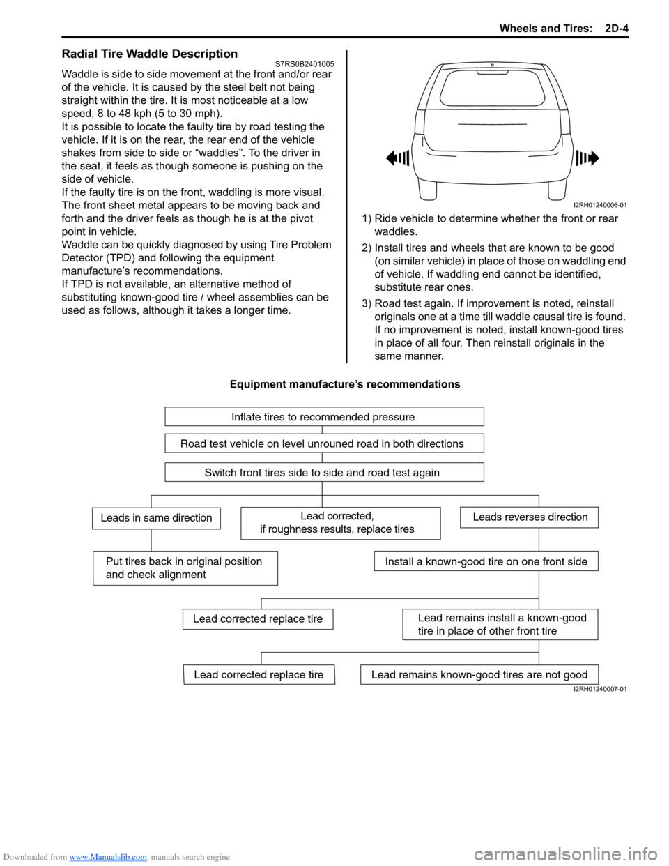
Waddle is side to side movement at the front and/or rear
of the vehicle. It is caused by the steel belt not being
straight within the tire. It is most noticeable at a low
speed, 8 to 48 kph (5 to 30 mph).
It is possible to locate the f aulty tire by road testing the
vehicle. If it is on the rear , the rear end of the vehicle
shakes from side to side or “waddles”. To the driver in
the seat, it feels as though someone is pushing on the
side of vehicle.
If the faulty tire is on the front, waddling is more visual.
The front sheet metal appears to be moving back and
forth and the driver feels as though he is at the pivot
point in vehicle.
Waddle can be quickly diagnosed by using Tire Problem
Detector (TPD) and following the equipment
manufacture’s recommendations.
If TPD is not available, an alternative method of
substituting known-good tire / wheel assemblies can be
used as follows, although it takes a longer time. 1) Ride vehicle to determine whether the front or rear
waddles.
2) Install tires and wheels that are known to be good (on similar vehicle) in place of those on waddling end
of vehicle. If waddling end cannot be identified,
substitute rear ones.
3) Road test again. If improvement is noted, reinstall originals one at a time till w addle causal tire is found.
If no improvement is noted, install known-good tires
in place of all four. Then reinstall originals in the
same manner.
Equipment manufacture’s recommendations
I2RH01240006-01
Inflate tires to recommended pressure
Road test vehicle on level unrouned road in both directions
Switch front tires side to side and road test again
Lead corrected,
if roughness results, replace tiresLeads in same directionLeads reverses direction
Put tires back in original position
and check alignmentInstall a known-good tire on one front side
Lead remains install a known-good
tire in place of other front tire
Lead remains known-good tires are not goodLead corrected replace tire
Lead corrected replace tire
I2RH01240007-01
Page 1029 of 1496
Downloaded from www.Manualslib.com manuals search engine Table of Contents 8- i
8
Section 8
CONTENTS
Restraint
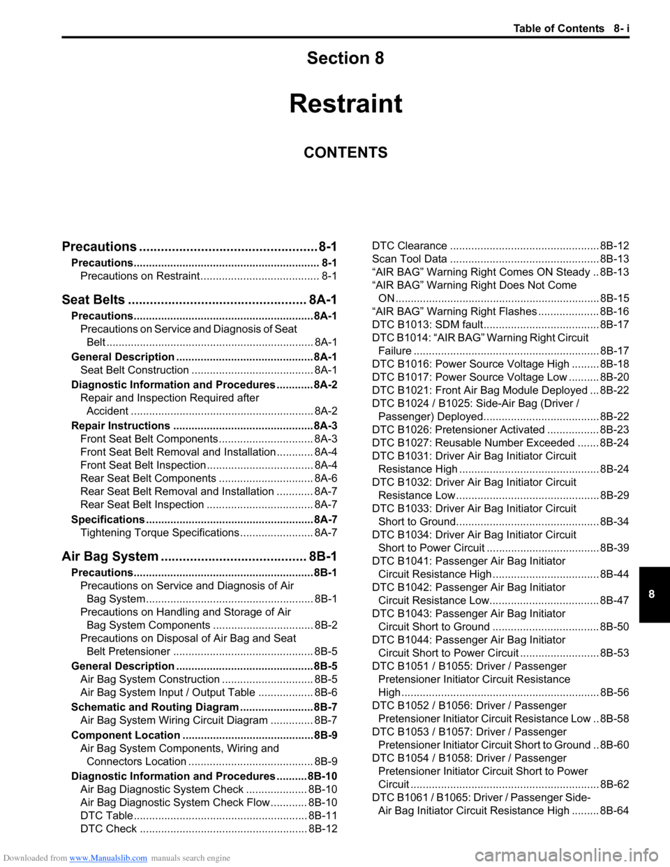
Precautions ................................................. 8-1
Precautions............................................................. 8-1
Precautions on Restraint ....................................... 8-1
Seat Belts .......... ............................... ........ 8A-1
Precautions........................................................... 8A-1
Precautions on Service a nd Diagnosis of Seat
Belt .................................................................... 8A-1
General Description ............................................. 8A-1 Seat Belt Construction ........................................ 8A-1
Diagnostic Information and Procedures ............ 8A-2 Repair and Inspection Required after Accident ............................................................ 8A-2
Repair Instructions .............................................. 8A-3 Front Seat Belt Components ............................... 8A-3
Front Seat Belt Removal and Installation ............ 8A-4
Front Seat Belt Inspection ................................... 8A-4
Rear Seat Belt Components ............................... 8A-6
Rear Seat Belt Removal and Installation ............ 8A-7
Rear Seat Belt Inspection ................................... 8A-7
Specifications ....................................................... 8A-7
Tightening Torque Specifications ........................ 8A-7
Air Bag System ............... ......................... 8B-1
Precautions........................................................... 8B-1
Precautions on Service and Diagnosis of Air Bag System....................................................... 8B-1
Precautions on Handling and Storage of Air Bag System Components . ................................ 8B-2
Precautions on Disposal of Air Bag and Seat
Belt Pretensioner .............................................. 8B-5
General Description ............................................. 8B-5 Air Bag System Construction .............................. 8B-5
Air Bag System Input / Output Table .................. 8B-6
Schematic and Routing Diagram ........................ 8B-7 Air Bag System Wiring Circuit Diagram .............. 8B-7
Component Locatio n ........................................... 8B-9
Air Bag System Components, Wiring and Connectors Location ......................................... 8B-9
Diagnostic Information and Procedures .......... 8B-10 Air Bag Diagnostic System Check .................... 8B-10
Air Bag Diagnostic System Check Flow ............ 8B-10
DTC Table ......................................................... 8B-11
DTC Check ....................................................... 8B-12 DTC Clearance ................................................. 8B-12
Scan Tool Data ................................................. 8B-13
“AIR BAG” Warning Right Comes ON Steady .. 8B-13
“AIR BAG” Warning Right Does Not Come
ON ................................................................... 8B-15
“AIR BAG” Warning Right Flashes .................... 8B-16
DTC B1013: SDM fault...................................... 8B-17
DTC B1014: “AIR BAG” Warning Right Circuit Failure ............................................................. 8B-17
DTC B1016: Power Source Voltage High ......... 8B-18
DTC B1017: Power Source Voltage Low .......... 8B-20
DTC B1021: Front Air Bag Module Deployed ... 8B-22
DTC B1024 / B1025: Side-Air Bag (Driver / Passenger) Deployed...................................... 8B-22
DTC B1026: Pretensioner Activated ................. 8B-23
DTC B1027: Reusable Number Exceeded ....... 8B-24
DTC B1031: Driver Air Bag Initiator Circuit
Resistance High .............................................. 8B-24
DTC B1032: Driver Air Bag Initiator Circuit
Resistance Low ............................................... 8B-29
DTC B1033: Driver Air Bag Initiator Circuit
Short to Ground............................................... 8B-34
DTC B1034: Driver Air Bag Initiator Circuit
Short to Power Circuit .... ................................. 8B-39
DTC B1041: Passenger Air Bag Initiator Circuit Resistance High ................................... 8B-44
DTC B1042: Passenger Air Bag Initiator Circuit Resistance Low.................................... 8B-47
DTC B1043: Passenger Air Bag Initiator Circuit Short to Ground ................................... 8B-50
DTC B1044: Passenger Air Bag Initiator Circuit Short to Power Circ uit .......................... 8B-53
DTC B1051 / B1055: Driver / Passenger Pretensioner Initiator Circuit Resistance
High ................................................................. 8B-56
DTC B1052 / B1056: Driver / Passenger Pretensioner Initiator Circu it Resistance Low .. 8B-58
DTC B1053 / B1057: Driver / Passenger Pretensioner Initiator Circuit Short to Ground .. 8B-60
DTC B1054 / B1058: Driver / Passenger Pretensioner Initiator Circuit Short to Power
Circuit .............................................................. 8B-62
DTC B1061 / B1065: Driver / Passenger Side- Air Bag Initiator Circuit Resistance High ......... 8B-64
Page 1032 of 1496
Downloaded from www.Manualslib.com manuals search engine 8A-1 Seat Belts:
Restraint
Seat Belts
Precautions
Precautions on Service and Diagnosis of Seat
Belt
S7RS0B8100001
WARNING!
If replacing seat belt is necessary, replace
buckle and seat belt assembly together as a
set. This is for the reason of ensuring locking
of tongue plate with buckle. If these parts are
replaced individually, such a locking
condition may become unreliable. For this
reason, SUZUKI will supply only the spare
buckle and seat belt assembly in a set part.
Before servicing or replacing seat belts, refer to the
following precautionary items.
• Seat belts should be normal relative to strap retractor and buckle portions. • Keep sharp edges and damaging objects away from
belts.
• Avoid bending or damaging any portion of belt buckle or latch plate.
• Do not bleach or dye belt webbing. (Use only mild soap and lukewarm water to clean it.)
• When installing a seat belt anchor bolt, it should be tightened by hand at first to prevent cross-threading
and then to specified torque.
• Do not attempt any repair s on retractor mechanisms
or retractor covers. Replace defective assemblies with
new replacement parts.
• Keep belts dry and clean at all times.
• If there exist any parts in question, replace such parts.
• Replace belts whose webbing is cut or otherwise damaged.
• Do not put anything into trim panel opening which seat belt webbing passes through.
General Description
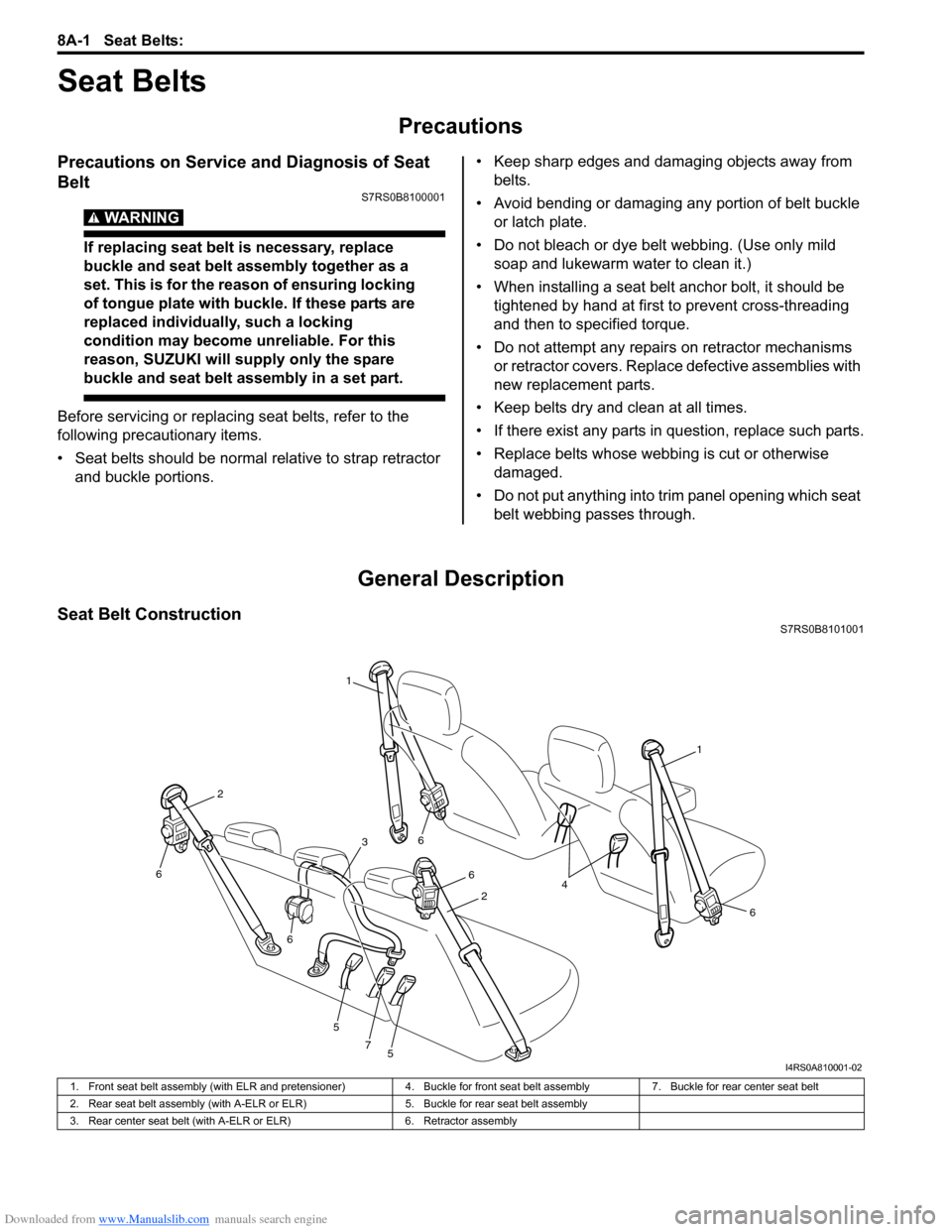
Seat Belt ConstructionS7RS0B8101001
1
1
6
6
6
5
5
7
6
6
2
2
3
4
I4RS0A810001-02
1. Front seat belt assembly (with ELR and pretensioner) 4. Buckle for front seat belt assembly7. Buckle for rear center seat belt
2. Rear seat belt assembly (with A-ELR or ELR) 5. Buckle for rear seat belt assembly
3. Rear center seat belt (with A-ELR or ELR) 6. Retractor assembly
Page 1037 of 1496
Downloaded from www.Manualslib.com manuals search engine Seat Belts: 8A-6
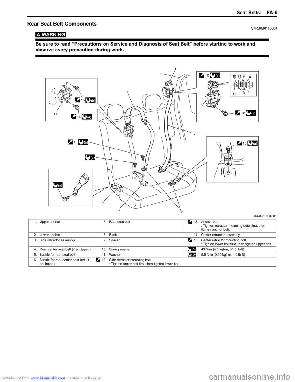
Rear Seat Belt ComponentsS7RS0B8106004
WARNING!
Be sure to read “Precautions on Service and Diagnosis of Seat Belt” before starting to work and
observe every precaution during work.
(b)
(a)
(a)
(a)
(a)
14
4
5
62
1
7
(a)
(a)
3
8
1
10
3
11911(a)
12
13
12
13
15
15
I6RS0C810002-01
1. Upper anchor 7. Rear seat belt 13. Anchor bolt
: Tighten retractor mounting bolts first, then
tighten anchor bolt.
2. Lower anchor 8. Bush 14. Center retractor assembly
3. Side retractor assembly 9. Spacer 15. Center retractor mounting bolt
: Tighten lower bolt first, then tighten upper bolt.
4. Rear center seat belt (if equipped) 10. Spring washer : 43 N⋅m (4.3 kgf-m, 31.5 lb-ft)
5. Buckle for rear seat belt 11. Washer : 5.5 N⋅m (0.55 kgf-m, 4.0 lb-ft)
6. Buckle for rear center seat belt (if equipped) 12. Side retractor mounting bolt
: Tighten upper bolt first, then tighten lower bolt.
Page 1038 of 1496
Downloaded from www.Manualslib.com manuals search engine 8A-7 Seat Belts:
Rear Seat Belt Removal and InstallationS7RS0B8106005
WARNING!
Be sure to read “Precautions on Service and
Diagnosis of Seat Belt” before starting to
work and observe every precaution during
work.
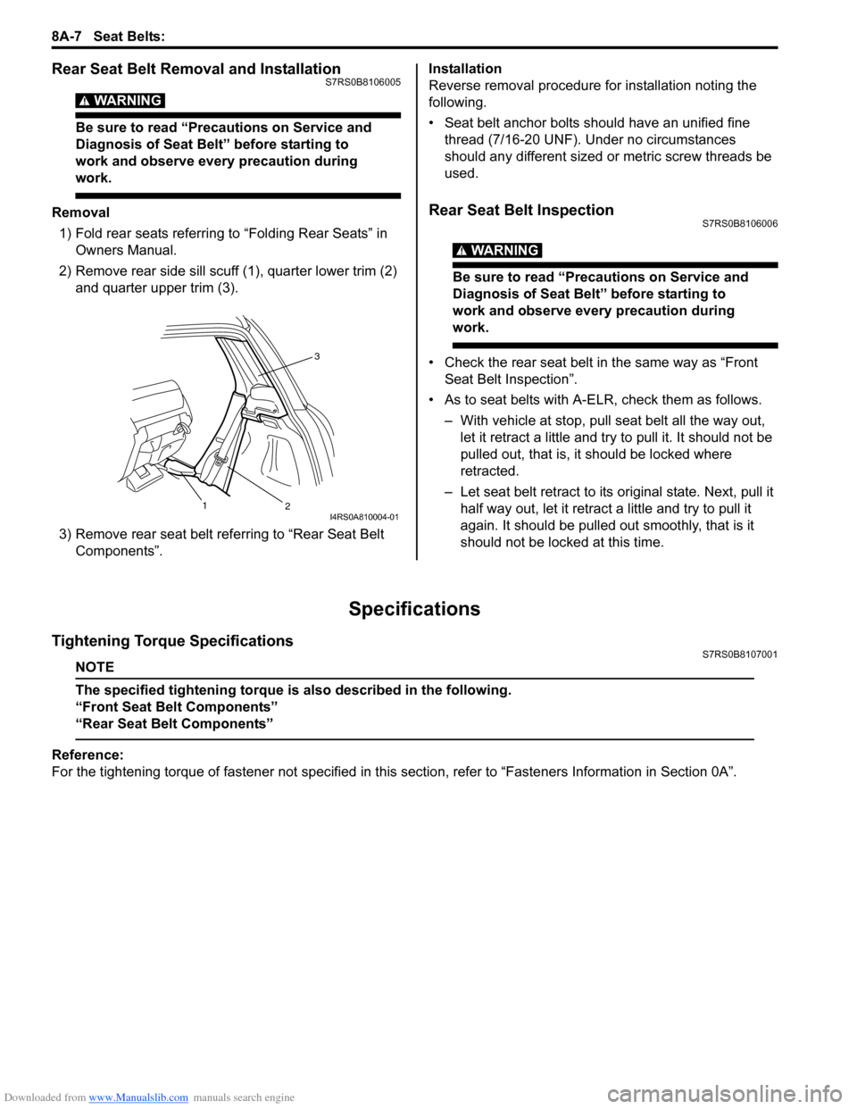
Removal1) Fold rear seats referring to “Folding Rear Seats” in Owners Manual.
2) Remove rear side sill scuff (1), quarter lower trim (2)
and quarter upper trim (3).
3) Remove rear seat belt referring to “Rear Seat Belt Components”. Installation
Reverse removal procedure for installation noting the
following.
• Seat belt anchor bolts should have an unified fine
thread (7/16-20 UNF). Under no circumstances
should any different sized or metric screw threads be
used.Rear Seat Belt InspectionS7RS0B8106006
WARNING!
Be sure to read “Precautions on Service and
Diagnosis of Seat Belt” before starting to
work and observe every precaution during
work.
• Check the rear seat belt in the same way as “Front Seat Belt Inspection”.
• As to seat belts with A-ELR, check them as follows. – With vehicle at stop, pull seat belt all the way out, let it retract a little and try to pull it. It should not be
pulled out, that is, it should be locked where
retracted.
– Let seat belt retract to its original state. Next, pull it
half way out, let it retrac t a little and try to pull it
again. It should be pulled out smoothly, that is it
should not be locked at this time.
Specifications
Tightening Torque SpecificationsS7RS0B8107001
NOTE
The specified tightening torque is also described in the following.
“Front Seat Belt Components”
“Rear Seat Belt Components”
Reference:
For the tightening torque of fastener not specified in this section, refer to “Fasteners Information in Section 0A”.
3
2
1
I4RS0A810004-01
Page 1044 of 1496
Downloaded from www.Manualslib.com manuals search engine 8B-6 Air Bag System:
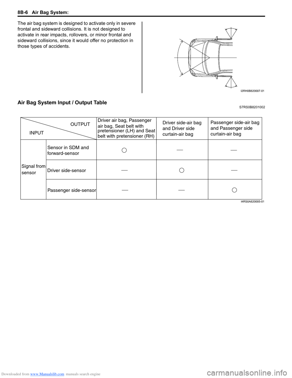
The air bag system is designed to activate only in severe
frontal and sideward collisions. It is not designed to
activate in rear impacts, rollovers, or minor frontal and
sideward collisions, since it would offer no protection in
those types of accidents.
Air Bag System Input / Output TableS7RS0B8201002
I2RH0B820007-01
INPUT
Sensor in SDM and
forward-sensor Driver side-air bag
and Driver side
curtain-air bag
Passenger side-air bag
and Passenger side
curtain-air bag
Driver side-sensor Passenger side-sensor OUTPUT
Signal from
sensor Driver air bag, Passenger
air bag, Seat belt with
pretensioner (LH) and Seat
belt with pretensioner (RH)
I4RS0A820005-01
Page 1095 of 1496
Downloaded from www.Manualslib.com manuals search engine Air Bag System: 8B-57
CAUTION!
• Be sure to perform “Air Bag Diagnostic System Check” before starting diagnosis according to flow.
• When measurement of resistance or voltage is required in this flow, use a tester along with a correct terminal adapter from special tool (Connector test adapter kit).
• When a check for proper connection is required, refer to “Inspection of Intermittent and Poor Connections”.
• If there is open circuit in the air bag wire harnes s, connector or terminal is found damaged, replace
the wire harness, connector and terminal as an assembly.
DTC Will Set when
The resistance of driver or passenger seat belt pretensioner initiator circuit is above a specified value for specified
time.
Flow Test Description
Step 1: Check if malfunction is in seat belt pretensioner.
Step 2: Check seat belt pretensioner initiator circuit.
DTC Troubleshooting
Step Action YesNo
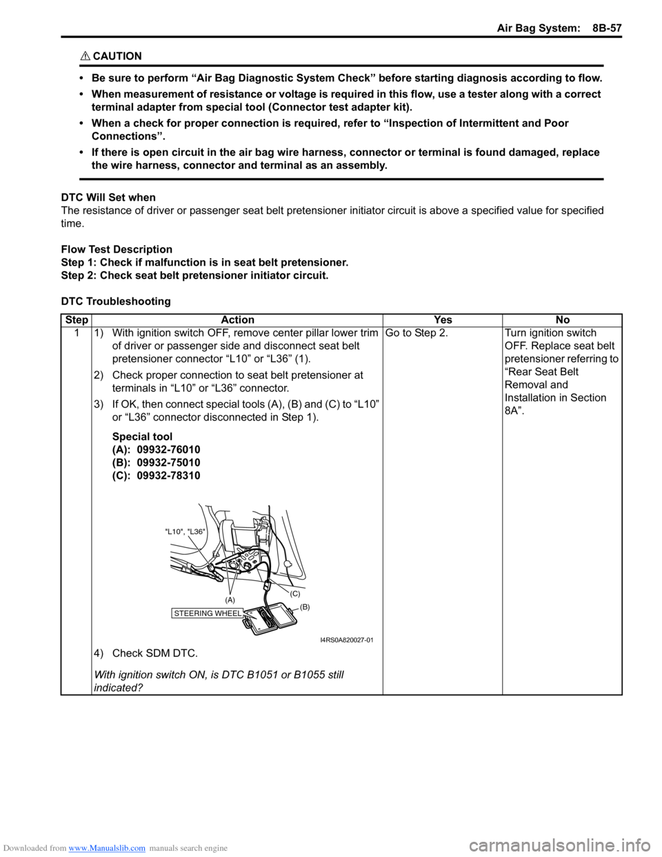
1 1) With ignition switch OFF, re move center pillar lower trim
of driver or passenger side and disconnect seat belt
pretensioner connector “L10” or “L36” (1).
2) Check proper connection to seat belt pretensioner at terminals in “L10” or “L36” connector.
3) If OK, then connect special tools (A), (B) and (C) to “L10” or “L36” connector disconnected in Step 1).
Special tool
(A): 09932-76010
(B): 09932-75010
(C): 09932-78310
4) Check SDM DTC.
With ignition switch ON, is DTC B1051 or B1055 still
indicated? Go to Step 2.
Turn ignition switch
OFF. Replace seat belt
pretensioner referring to
“Rear Seat Belt
Removal and
Installation in Section
8A”.
STEERING WHEEL(B)
(C)
(A)
"L10", "L36"
I4RS0A820027-01
Page 1159 of 1496
Downloaded from www.Manualslib.com manuals search engine Air Bag System: 8B-121
Deployment / Activation Inside of Vehicle
When the vehicle will be destroyed, or salvaged for
component parts, deploy the air bag modules and/or
activate seat belt pretensioners installed on vehicle.
NOTE
If equipped with the seat belt pretensioners,
activate both side of seat belt pretensioners
at the same time when using special tool (C).
1) Turn ignition switch to LOCK position, remove key
and put on safety glasses.
2) Remove all loose objects from front seats and instrument panel.
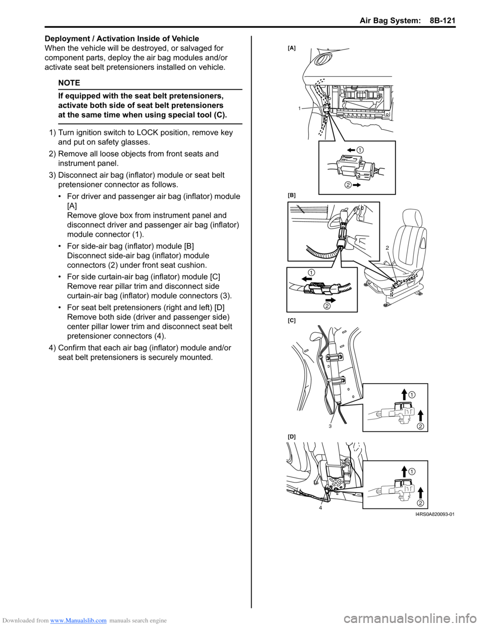
3) Disconnect air bag (inflator) module or seat belt pretensioner connector as follows.
• For driver and passenger air bag (inflator) module [A]
Remove glove box from instrument panel and
disconnect driver and passenger air bag (inflator)
module connector (1).
• For side-air bag (inflator) module [B] Disconnect side-air bag (inflator) module
connectors (2) under front seat cushion.
• For side curtain-air bag (inflator) module [C] Remove rear pillar trim and disconnect side
curtain-air bag (inflator) module connectors (3).
• For seat belt pretensioners (right and left) [D] Remove both side (driver and passenger side)
center pillar lower trim an d disconnect seat belt
pretensioner connectors (4).
4) Confirm that each air bag (inflator) module and/or seat belt pretensioners is securely mounted.
[A]
[B]
[C]
[D]
2
1
3
4
1
2
1
2
1
2
1
2
I4RS0A820093-01