2006 SUZUKI SWIFT Cv joint
[x] Cancel search: Cv jointPage 304 of 1496

Downloaded from www.Manualslib.com manuals search engine 1D-19 Engine Mechanical:
24) Before removing engine with transaxle from engine compartment, recheck to make sure all hoses,
electric wires and cables are disconnected from
engine and transaxle.
25) Lower engine with transaxle from engine compartment.
CAUTION!
Before lowering engine, to avoid damage to
A/C compressor and clutch operating
cylinder, make clearance by rising them. Be
sure not to damage suspended A/C
compressor and clutch operating cylinder.
26) Disconnect transaxle from engine, referring to “Manual Transaxle Unit Dismounting and
Remounting in Section 5B” or “Automatic Transaxle
Unit Dismounting and Re mounting in Section 5A”.
27) For M/T model, remove clutch cover and clutch disk referring to “Clutch Cover, Clutch Disc and Flywheel
Removal and Installa tion in Section 5C”.
Installation 1) For M/T model, install clutch cover and clutch disk referring to “Clutch Cover, Clutch Disc and Flywheel
Removal and Installa tion in Section 5C”.
2) Connect transaxle to engine referring to “Manual Transaxle Unit Dismounting and Remounting in
Section 5B” or “Automatic Transaxle Unit
Dismounting and Remounting in Section 5A”.
3) Lift engine and transaxle into engine compartment with jack.
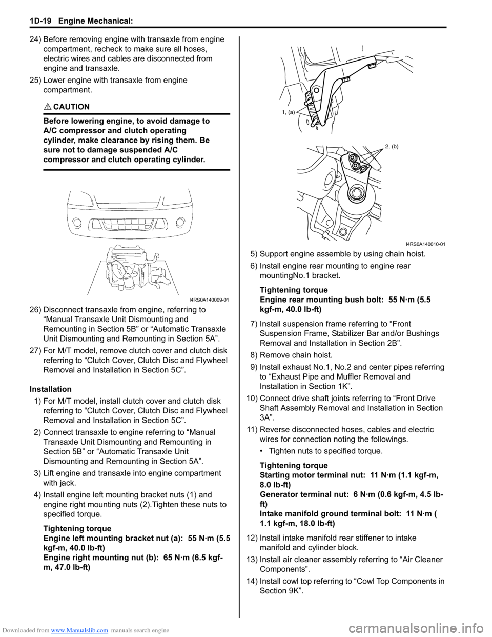
4) Install engine left mounting bracket nuts (1) and engine right mounting nuts (2).Tighten these nuts to
specified torque.
Tightening torque
Engine left mounting bracket nut (a): 55 N·m (5.5
kgf-m, 40.0 lb-ft)
Engine right mounting nut (b): 65 N·m (6.5 kgf-
m, 47.0 lb-ft) 5) Support engine assemble by using chain hoist.
6) Install engine rear mounting to engine rear
mountingNo.1 bracket.
Tightening torque
Engine rear mounting bush bolt: 55 N·m (5.5
kgf-m, 40.0 lb-ft)
7) Install suspension frame referring to “Front Suspension Frame, Stabiliz er Bar and/or Bushings
Removal and Installati on in Section 2B”.
8) Remove chain hoist.
9) Install exhaust No.1, No.2 and center pipes referring to “Exhaust Pipe and Muffler Removal and
Installation in Section 1K”.
10) Connect drive shaft joints referring to “Front Drive Shaft Assembly Removal and Installation in Section
3A”.
11) Reverse disconnected hoses, cables and electric wires for connection noting the followings.
• Tighten nuts to specified torque.
Tightening torque
Starting motor terminal nut: 11 N·m (1.1 kgf-m,
8.0 lb-ft)
Generator terminal nut: 6 N·m (0.6 kgf-m, 4.5 lb-
ft)
Intake manifold ground terminal bolt: 11 N·m (
1.1 kgf-m, 18.0 lb-ft)
12) Install intake manifold rear stiffener to intake
manifold and cylinder block.
13) Install air cleaner assembly referring to “Air Cleaner Components”.
14) Install cowl top referring to “Cowl Top Components in
Section 9K”.
I4RS0A140009-01
1, (a)
2, (b)
I4RS0A140010-01
Page 327 of 1496

Downloaded from www.Manualslib.com manuals search engine Engine Mechanical: 1D-42
Cylinder Head InspectionS7RS0B1406027
• Remove all carbon deposits from combustion chambers.
NOTE
Do not use any sharp-edged tool to scrape
off carbon deposits. Be careful not to scuff or
nick metal surfaces when decarbonizing. The
same applies to valves and valve seats, too.
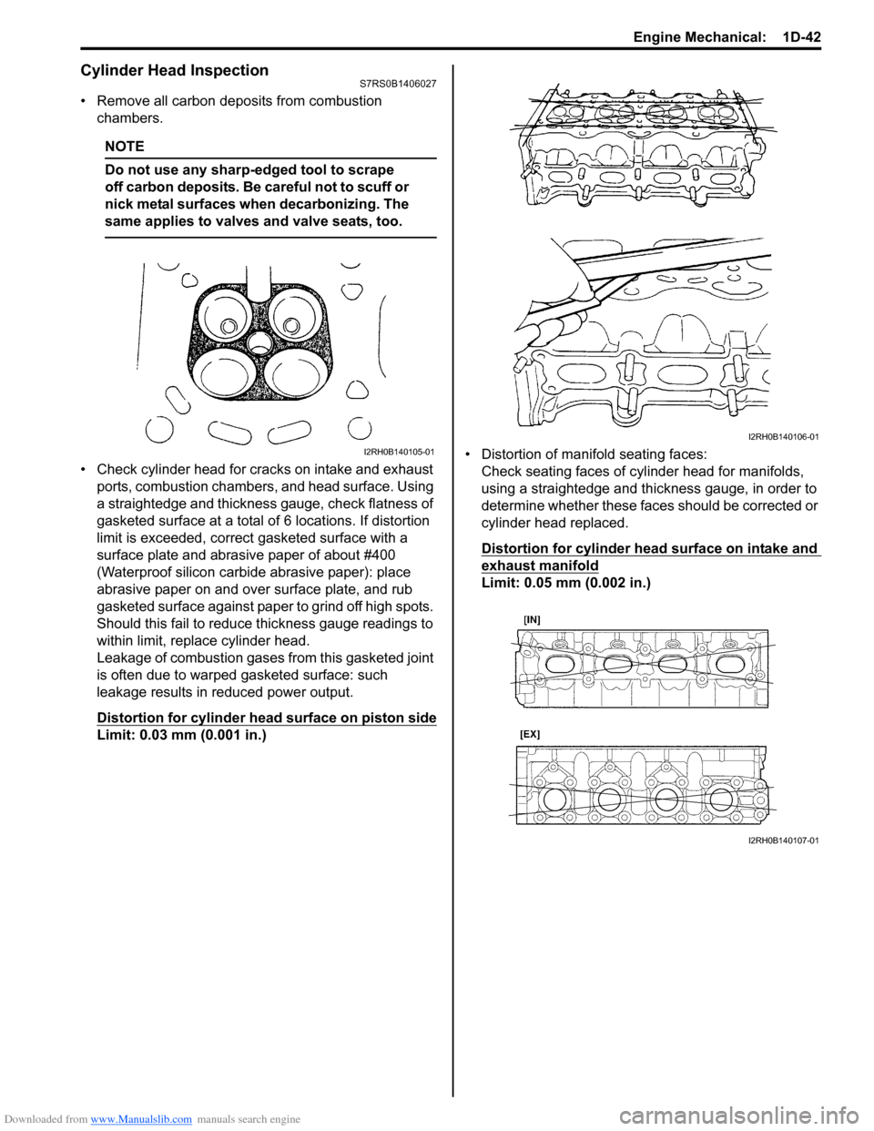
• Check cylinder head for cracks on intake and exhaust ports, combustion chambers, and head surface. Using
a straightedge and thickness gauge, check flatness of
gasketed surface at a total of 6 locations. If distortion
limit is exceeded, correct gasketed surface with a
surface plate and abrasive paper of about #400
(Waterproof silicon carbide abrasive paper): place
abrasive paper on and over surface plate, and rub
gasketed surface against paper to grind off high spots.
Should this fail to reduce thickness gauge readings to
within limit, replace cylinder head.
Leakage of combustion gases from this gasketed joint
is often due to warped gasketed surface: such
leakage results in reduced power output.
Distortion for cylinder head surface on piston side
Limit: 0.03 mm (0.001 in.) • Distortion of manifold seating faces:
Check seating faces of cylinder head for manifolds,
using a straightedge and thickness gauge, in order to
determine whether these faces should be corrected or
cylinder head replaced.
Distortion for cylinder head surface on intake and
exhaust manifold
Limit: 0.05 mm (0.002 in.)
I2RH0B140105-01
I2RH0B140106-01
I2RH0B140107-01
Page 378 of 1496

Downloaded from www.Manualslib.com manuals search engine 1G-3 Fuel System:
4) Check that battery voltage is 11 V or more.
5) Measure fuel pressure at each condition.If measured pressure is out of specification, refer to
“Fuel Pressure Check in Section 1A” and check each
possibly defective part. Replace if found defective.
a) Turn ignition switch ON to operate fuel pump and after 2 seconds turn it OFF. Repeat this 3 or 4
times and then check fuel pressure.
Fuel pressure specification
With fuel pump operating and engine
stopped: 270 – 310 kPa (2.7 – 3.1 kg/cm2, 38.4
– 44.0 psi)
b) Start engine and warm it up to normal operating temperature, and measure fuel pressure at
idling.
Fuel pressure specification
At specified idle speed: 270 – 310 kPa (2.7 –
3.1 kg/cm2, 38.4 – 44.0 psi)
c) Stop engine, and measure fuel pressure at one minute after stopping.
Fuel pressure specification
With 1 min. after engine (fuel pump) stop
(Pressure reduces as time passes): Over 300
kPa (3.0 kg/cm
2, 42.7 psi)
6) After checking fuel pressure, remove fuel pressure gauge.
WARNING!
As fuel feed line is still under high fuel
pressure, make sure to release fuel pressure
according to the following procedures.
• Place fuel container under joint.
• Cover joint with rag and loosen joint nut slowly in order to release fuel pressure
gradually.
7) Remove special tools from fuel delivery pipe and fuel feed hose.
8) Connect fuel feed hose to fuel delivery pipe and clamp it securely.
9) With engine OFF and ignition switch ON, check for fuel leaks.
Fuel Cut Operation InspectionS7RS0B1704002
NOTE
Before inspection, make sure that gear shift
lever is in neutral positi on (shift select lever
is “P” range for A/T vehicle), A/C is OFF and
parking brake lever is pulled all the way up.
1) Warm engine up to normal operating temperature.
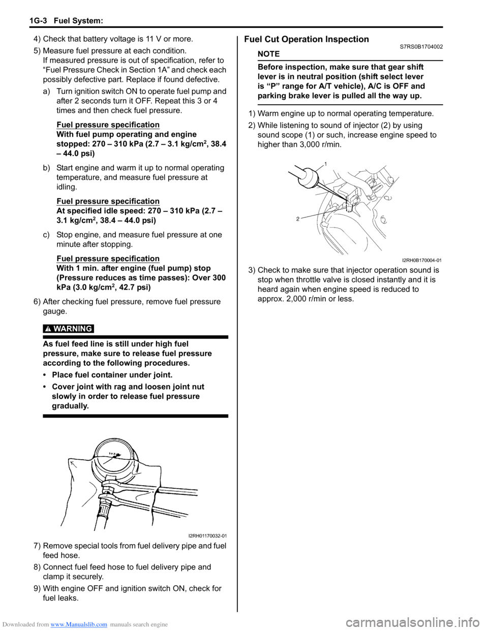
2) While listening to sound of injector (2) by using sound scope (1) or such, increase engine speed to
higher than 3,000 r/min.
3) Check to make sure that injector operation sound is stop when throttle valve is closed instantly and it is
heard again when engine speed is reduced to
approx. 2,000 r/min or less.
I2RH01170032-01
I2RH0B170004-01
Page 380 of 1496

Downloaded from www.Manualslib.com manuals search engine 1G-5 Fuel System:
Fuel Hose Disconnecting and ReconnectingS7RS0B1706002
WARNING!
Before starting the following procedure, be sure to observe “Precautions on Fuel System Service” in
order to reduce the risk or fire and personal injury.
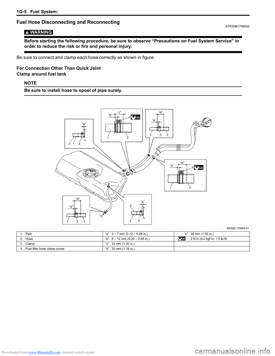
Be sure to connect and clamp each hose correctly as shown in figure.
For Connection Other Than Quick Joint
Clamp around fuel tank
NOTE
Be sure to install hose to spool of pipe surely.
I6RS0C170004-01
1. Pipe “a” 3 – 7 mm (0.12 – 0.28 in.)“e” 38 mm (1.50 in.)
2. Hose “b” 5 – 12 mm (0.20 – 0.48 in.): 2 N⋅m (0.2 kgf-m, 1.5 lb-ft)
3. Clamp “c” 33 mm (1.30 in.)
4. Fuel filler hose clamp screw “d” 30 mm (1.18 in.)
Page 381 of 1496

Downloaded from www.Manualslib.com manuals search engine Fuel System: 1G-6
Clamp other than around fuel tankFor Quick Joint
Disconnecting1) Remove mud, dust and/or foreign material between pipe (1) and quick joint (2) by blowing compressed
air.
2) Unlock joint lock by insert ing special tool between
pipe and quick joint.
Special tool
(A): 09919–47020
3) Disconnect quick joint from pipe.
Reconnecting
Insert quick joint to fuel pipe until they lock securely (a
click is heard), and confi rm that quick joint is not
disconnected by hand.
I3RM0A170001-01
[A]: With short pipe, fit hose as far as it reaches pipe joint as shown.
[B]: With the following type pipe, fit hose as far as its peripheral projection
as shown.
[C]: With bent pipe, fit hose as its bent part as shown or till depth “b”.
[D]: With straight pipe, fit hose till depth “b”.
[E]: With red marked pipe, fit hose end reaches red mark on pipe.
[F]: For fuel tank filler hose, insert it to spool or welding-bead.
“a”: Clamp securely at a position 3 – 7 mm (0.12 – 0.27 in.) from hose end.
“b”: 20 – 30 mm (0.79 – 1.18 in.) “c”: 0 – 5 mm (0 – 0.19 in.)
“d”: 5 – 12 mm (0.2 – 0.47 in.)
“e”: 40 mm (1.57 in.) 1. Pipe
2. Hose
3. Clamp
4. Red mark
1
2 1
2
(A)
I4RS0A170019-01
Page 382 of 1496

Downloaded from www.Manualslib.com manuals search engine 1G-7 Fuel System:
Fuel Pressure Relief ProcedureS7RS0B1706003
CAUTION!
This work must not be done when engine is
hot. If done so, it may cause adverse effect to
catalyst.
NOTE
If ECM detects DTC(s) after servicing, clear
DTC(s) referring to “DTC Clearance in
Section 1A”.
1) Make sure that engine is cold.
2) Shift transaxle gear shift lever in “Neutral” (shift select lever in “P” range for A/T model), set parking
brake and block drive wheels.
3) Remove relay / fuse box cover.
4) Disconnect fuel pump relay (1) from relay / fuse box (2).
5) Remove fuel filter cap in order to release fuel vapor pressure in fuel tank, and then reinstall it.
6) Start engine and run it until engine stops for lack of fuel. Repeat cranking engine 2 – 3 times for about 3
seconds each time in order to dissipate fuel pressure
in lines. Fuel connections are now safe for servicing.
7) After servicing, connect fuel pump relay (1) to relay / fuse box and install re lay / fuse box cover.
Fuel Leakage Check ProcedureS7RS0B1706004
After performing any service on fuel system, check to
make sure that there are no fuel leakages as follows.
1) Turn ON ignition switch for 3 seconds (to operate fuel pump) and then turn it OFF.
Repeat this (ON and OFF) 3 or 4 times and apply
fuel pressure to fuel line until fuel pressure is felt by
hand placed on fuel feed hose.
2) In this state, check to see that there are no fuel leakages from any part of fuel system.
Fuel Lines On-Vehicle InspectionS7RS0B1706005
CAUTION!
Due to the fact that fuel feed line (1) is under
high pressure, use special care when
servicing it.
Visually inspect fuel lines for evidence of fuel leakage,
hose crack and deterioration or damage.
Make sure all cl amps are secure.
Replace parts as needed.
Fuel Pipe Removal and InstallationS7RS0B1706006
WARNING!
Before starting the following procedure, be
sure to observe “Precautions on Fuel System
Service” in order to reduce the risk or fire
and personal injury.
Removal
1) Relieve fuel pressure in fuel feed line according to “Fuel Pressure Relief Procedure”.
2) Disconnect negative cable at battery.
3) Disconnect fuel pipe joint and fuel hose (3) from fuel pipe (2) at the front and rear of each fuel pipe
referring to “Fuel Hose Disconnecting and
Reconnecting”.
4) Mark the location of clamps (1) on fuel pipes (2), so that the clamps can be reinstalled to where they
were.
5) Remove pipes (2) with clamp (1) from vehicle.
6) Remove clamp (1) from pipes (2).
1
I4RS0A170004-01
1
I4RS0A170005-01
2
13
I4RS0A170020-01
Page 387 of 1496

Downloaded from www.Manualslib.com manuals search engine Fuel System: 1G-12
Fuel Tank Inlet Valve InspectionS7RS0B1706012
WARNING!
Before starting the following procedure, be
sure to observe “Precautions on Fuel System
Service” in order to reduce the risk or fire
and personal injury.
Check fuel tank inlet valve for the following.
If any damage or malfunction is found, replace.
•Damage
• Smooth opening and closing
Fuel Tank Removal and InstallationS7RS0B1706013
WARNING!
Before starting the following procedure, be
sure to observe “Precautions on Fuel System
Service” in order to reduce the risk or fire
and personal injury.
Removal1) Relieve fuel pressure in fuel feed line according to
“Fuel Pressure Relief Procedure”.
2) Disconnect negative cable at battery.
3) Hoist vehicle.
4) Remove exhaust center pipe.
5) Disconnect fuel filler hose and breather hose from
filler neck referring to “Fue l Tank Inlet Valve Removal
and Installation”.
6) Due to absence of fuel tank drain plug, drain fuel tank by pumping fuel out through fuel tank filler.
Use hand operated pump device to drain fuel tank.
CAUTION!
• Do not force pump hose into fuel tank, or pump hose may damage fuel tank inlet
valve.
• Never store fuel in an open container due to possibility of fire or explosion.
7) Disconnect fuel pipe joint and fuel hoses (1) from fuel pipes (2) referring to “Fuel Hose Disconnecting
and Reconnecting”.
8) Support fuel tank (1) with jack (2) and remove its mounting bolts.
9) Lower fuel tank a little as to disconnect wire harness at connector (1) and ground wire (2), then remove
fuel tank.
I2RH0B170019-01
12
I4RS0A170008-01
12
I4RS0A170009-01
1
2
I6RS0C170005-02
Page 388 of 1496

Downloaded from www.Manualslib.com manuals search engine 1G-13 Fuel System:
Installation
CAUTION!
• When connecting joint, clean outside surfaces of pipe where joint is to be
inserted, push joint into pipe till joint lock
clicks and check to ensure that pipes are
connected securely, or fuel leak may
occur.
• Never let the fuel hoses touch the ABS sensor harness (if equipped).
1) If parts have been removed from fuel tank, install them before installing fuel tank to vehicle.
2) Raise fuel tank (1) with jack (2) and connect fuel pump connector (3), ground wire (4) and clamp wire
harness.
Tightening torque
Ground wire bolt (a): 11 N·m (1.1 kgf-m, 8.0 lb-ft)
3) Install fuel tank to vehicle. Tightening torque
Fuel tank bolt (b): 45 N·m (4.5 kgf-m, 33.0 lb-ft) 4) Connect fuel filler hose (1
) and breather hose (2) to
filler neck (3) as shown in figure, and clamp them
securely.
Tightening torque
Fuel filler hose clamp (a): 2 N·m (0.2 kgf-m, 1.5
lb-ft)
5) Connect fuel feed hose (1) and vapor hose (2) to each pipe as shown in figure, and clamp them
securely.
6) Install exhaust center pipe referring to “Exhaust Pipe and Muffler Removal and Installation in Section 1K”.
7) Connect negative cable at battery.
8) With engine OFF, turn ignition switch to ON position and check for fuel leaks.
Fuel Tank InspectionS7RS0B1706014
After removing fuel tank, check hoses and pipes
connected to fuel tank for leaks, loose connections,
deterioration or damage. Also check fuel pump
assembly gaskets for leaks, visually inspect fuel tank for
leaks and damage.
Replace any damaged or malconditioned parts.
(b)(b)
1
2
3
4
(a)
I6RS0C170006-02
1
2
(a)
3
I4RS0A170012-01
1
2
I4RS0A170013-01