2006 SUZUKI SWIFT dim light
[x] Cancel search: dim lightPage 75 of 1496
Downloaded from www.Manualslib.com manuals search engine Engine General Information and Diagnosis: 1A-25
Step 2: DTC / Freeze Frame Data Check, Record and
Clearance
First, check DTC (including pending DTC), referring to
“DTC Check”. If DTC is indicated, print it and freeze
frame data or write them down and then clear them by
referring to “DTC Clearance”. DTC indicates malfunction
that occurred in the system but does not indicate
whether it exists now or it occurred in the past and the
normal condition has been restored now. To check which
case applies, check the sy mptom in question according
to Step 5 and recheck DTC according to Step 6 and 7.
Attempt to diagnose a trouble based on DTC in this step
only or failure to clear the DTC in this step will lead to
incorrect diagnosis, trouble diagnosis of a normal circuit
or difficulty in troubleshooting.
Step 3 and 4: Visual Inspection
As a preliminary step, be sure to perform visual check of
the items that support proper function of the engine
referring to “Visual Inspection”.
Step 5: Trouble Symptom Confirmation
Based on information obtained in “Step 1: Customer
Complaint Analysis: ” and “Step 2: DTC / Freeze Frame
Data Check, Record and Clearance: ”, confirm trouble
symptoms. Also, reconfirm DTC according to “DTC
Confirmation Procedure” described in each DTC diag.
flow.
Step 6 and 7: Rechecking and Record of DTC /
Freeze Frame Data
Refer to “DTC Check” for checking procedure.
Step 8: Engine Basic Inspection and Engine
Symptom Diagnosis
Perform basic engine check according to “Engine Basic
Inspection” first. When the end of the flow has been
reached, check the parts of the system suspected as a
possible cause referring to “Engine Symptom Diagnosis”
and based on symptoms appearing on the vehicle
(symptoms obtained through steps of customer
complaint analysis, trouble symptom confirmation and/or
basic engine check) and repair or replace faulty parts, if
any.
Step 9: Troubleshooting for DTC (See each DTC
Diag. Flow)
Based on the DTC indicated in Step 6 or 7 and referring
to the applicable DTC diag. flow, locate the cause of the
trouble, namely in a sensor, switch, wire harness,
connector, actuator, ECM or other part and repair or
replace faulty parts. Step 10: Intermittent Problems Check
Check parts where an intermit
tent trouble is easy to
occur (e.g., wire harness, connector, etc.), referring to
“Intermittent and Poor Connec tion Inspection in Section
00” and related circuit of DTC recorded in Step 2.
Step 11: Final Confirmation Test
Confirm that the problem symptom has gone and the
engine is free from any abnormal conditions. If what has
been repaired is re lated to the DTC, clear the DTC once,
perform DTC confirmation procedure and confirm that no
DTC is indicated.
Malfunction Indicator Lamp (MIL) CheckS7RS0B1104002
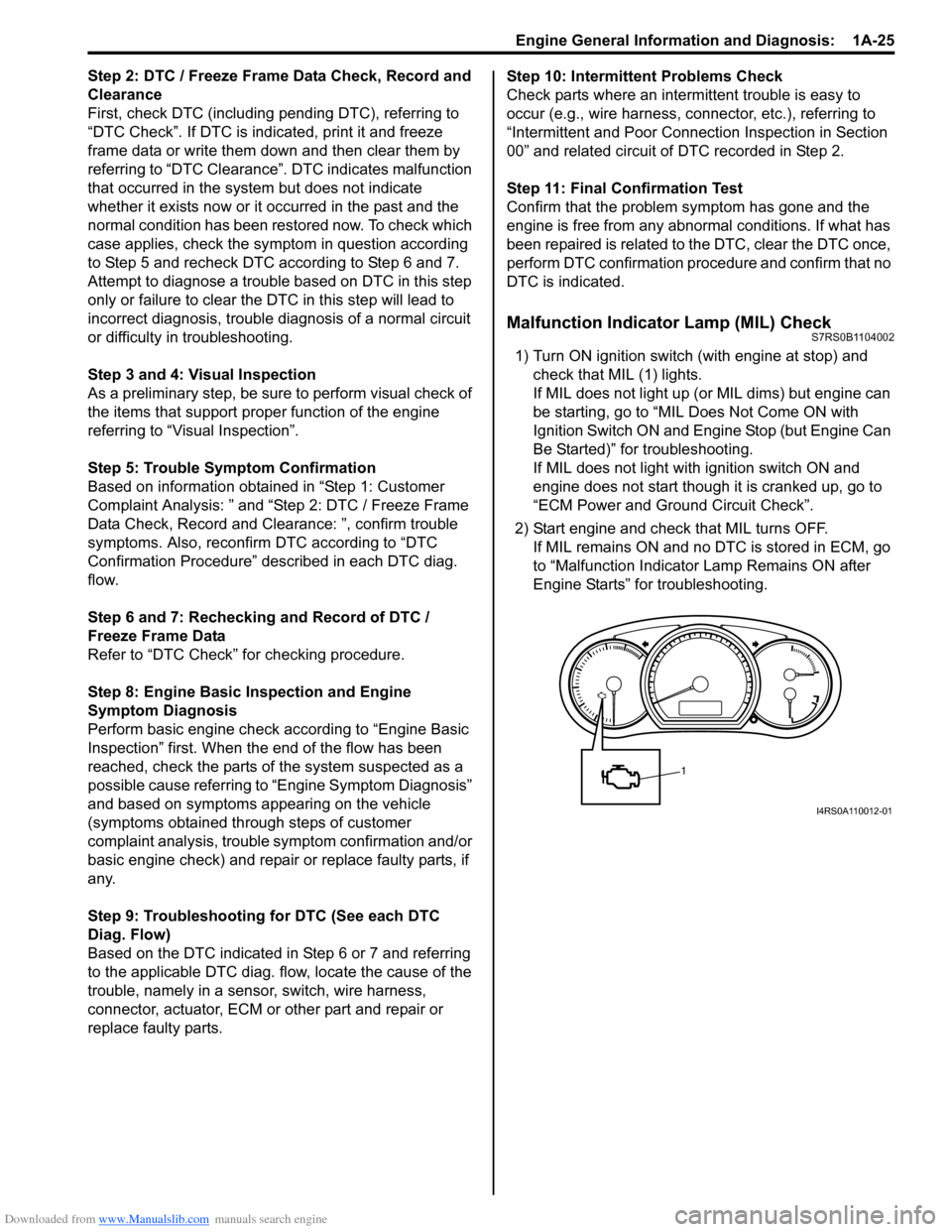
1) Turn ON ignition switch (with engine at stop) and check that MIL (1) lights.
If MIL does not light up (or MIL dims) but engine can
be starting, go to “MIL Does Not Come ON with
Ignition Switch ON and Engine Stop (but Engine Can
Be Started)” for troubleshooting.
If MIL does not light with ignition switch ON and
engine does not start though it is cranked up, go to
“ECM Power and Ground Circuit Check”.
2) Start engine and check that MIL turns OFF. If MIL remains ON and no DTC is stored in ECM, go
to “Malfunction Indicator Lamp Remains ON after
Engine Starts” for troubleshooting.
1
I4RS0A110012-01
Page 806 of 1496
Downloaded from www.Manualslib.com manuals search engine 5A-162 Automatic Transmission/Transaxle:
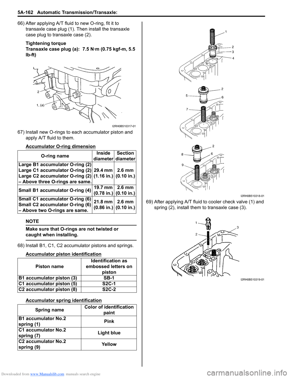
66) After applying A/T fluid to new O-ring, fit it to transaxle case plug (1). Then install the transaxle
case plug to transaxle case (2).
Tightening torque
Transaxle case plug (a): 7.5 N·m (0.75 kgf-m, 5.5
lb-ft)
67) Install new O-rings to each accumulator piston and apply A/T fluid to them.
Accumulator O-ri ng dimension
NOTE
Make sure that O-rings are not twisted or
caught when installing.
68) Install B1, C1, C2 accumulator pistons and springs.
Accumulator piston identification
Accumulator spring identification
69) After applying A/T fluid to cooler check valve (1) and
spring (2), install them to transaxle case (3).
O-ring name
Inside
diameter Section
diameter
Large B1 accumula tor O-ring (2)
Large C1 accumula tor O-ring (2)
Large C2 accumula tor O-ring (2)
– Above three O-rings are same. 29.4 mm
(1.16 in.) 2.6 mm
(0.10 in.)
Small B1 accumulator O-ring (4) 19.7 mm
(0.78 in.) 2.6 mm
(0.10 in.)
Small C1 accumulator O-ring (6)
Small C2 accumulator O-ring (6)
– Above two O-rings are same. 21.8 mm
(0.86 in.) 2.6 mm
(0.10 in.)
Piston name Identification as
embossed letters on piston
B1 accumulator piston (3) SB-1
C1 accumulator piston (5) S2C-1
C2 accumulator piston (8) S2C-2
Spring name Color of identification
paint
B1 accumulator No.2
spring (1) Pink
C1 accumulator No.2
spring (7) Light blue
C2 accumulator No.2
spring (9) Yellow
I2RH0B510317-01
I2RH0B510318-01
I2RH0B510319-01
Page 1248 of 1496
Downloaded from www.Manualslib.com manuals search engine 9A-77 Wiring Systems:
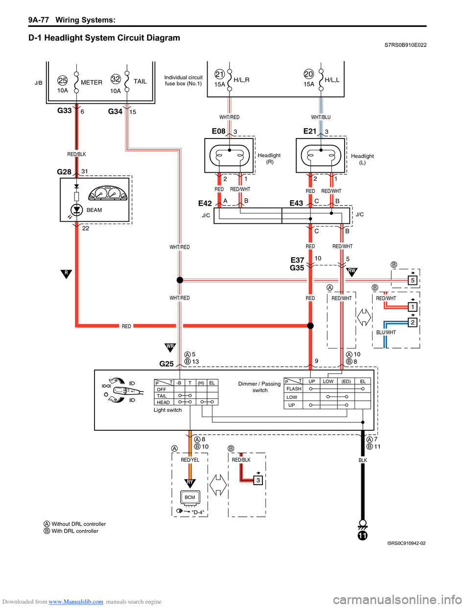
D-1 Headlight System Circuit DiagramS7RS0B910E022
1
Headlight (R) Headlight
(L)
WHT/BLU
RED
Dimmer / Passing switch
Light switch
2
2
BA BC
B
C
33
15
1
22G28
E08
G34
E21
G336
31
RED/BLK
WHT/RED
WHT/RED
10A
25METER
WHT/RED
9
BLK
11
G25
15A
21
15A
20H/L,R H/L,L
RED/WHTRED
10
RED
RED
J/B
10ATAIL
32
RED/WHTRED/WHT
BLU/WHT
5
RED/WHT
E37
G35
E42
J/C
REDRED/WHT
BEAM
FLASH UPLOW
T
P(ED)EL
UP
LOW
OFF
TAIL
HEAD -BT
T
P(H) EL
RY
RED/YEL
"D-4"
BCM
R
WR
RW
E43
J/C
Individual circuit
fuse box (No.1)
Without DRL controller
AWith DRL controller
B
A
5
1
2
3
AB
B
RED/BLK
B
AB5
13AB10
8
AB7
11AB8
10
I5RS0C910942-02
Page 1284 of 1496
Downloaded from www.Manualslib.com manuals search engine 9B-2 Lighting Systems:
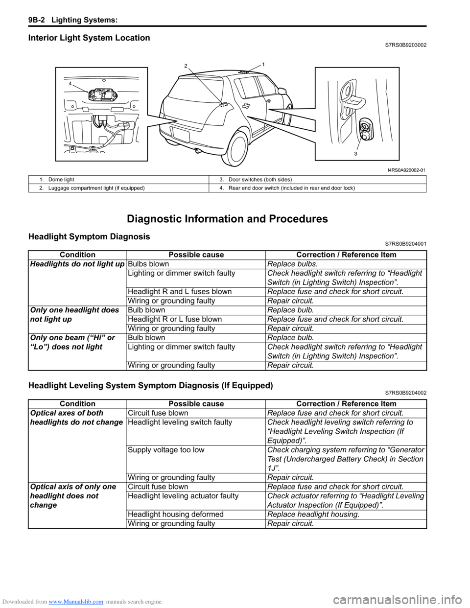
Interior Light System LocationS7RS0B9203002
Diagnostic Information and Procedures
Headlight Symptom DiagnosisS7RS0B9204001
Headlight Leveling System Symptom Diagnosis (If Equipped)S7RS0B9204002
13
2
4
I4RS0A920002-01
1. Dome light 3. Door switches (both sides)
2. Luggage compartment light (if equipped) 4. Rear end door switch (included in rear end door lock)
ConditionPossible cause Correction / Reference Item
Headlights do not light up Bulbs blown Replace bulbs.
Lighting or dimmer switch faulty Check headlight switch referring to “Headlight
Switch (in Lighting Switch) Inspection”.
Headlight R and L fuses blown Replace fuse and check for short circuit.
Wiring or grounding faulty Repair circuit.
Only one headlight does
not light up Bulb blown
Replace bulb.
Headlight R or L fuse blown Replace fuse and check for short circuit.
Wiring or grounding faulty Repair circuit.
Only one beam (“Hi” or
“Lo”) does not light Bulb blown
Replace bulb.
Lighting or dimmer switch faulty Check headlight switch referring to “Headlight
Switch (in Lighting Switch) Inspection”.
Wiring or grounding faulty Repair circuit.
ConditionPossible cause Correction / Reference Item
Optical axes of both
headlights do not change Circuit fuse blown
Replace fuse and check for short circuit.
Headlight leveling switch faulty Check headlight leveling switch referring to
“Headlight Leveling Switch Inspection (If
Equipped)”.
Supply voltage too low Check charging system referring to “Generator
Test (Undercharged Battery Check) in Section
1J”.
Wiring or grounding faulty Repair circuit.
Optical axis of only one
headlight does not
change Circuit fuse blown
Replace fuse and check for short circuit.
Headlight leveling actuator faulty Check actuator referring to “Headlight Leveling
Actuator Inspection (If Equipped)”.
Headlight housing deformed Replace headlight housing.
Wiring or grounding faulty Repair circuit.
Page 1285 of 1496
Downloaded from www.Manualslib.com manuals search engine Lighting Systems: 9B-3
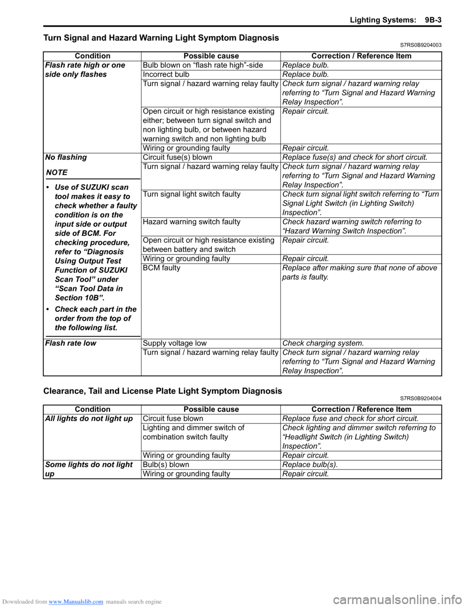
Turn Signal and Hazard Warning Light Symptom DiagnosisS7RS0B9204003
Clearance, Tail and License Plate Light Symptom DiagnosisS7RS0B9204004
ConditionPossible cause Correction / Reference Item
Flash rate high or one
side only flashes Bulb blown on “flash rate high”-side
Replace bulb.
Incorrect bulb Replace bulb.
Turn signal / hazard warning relay faulty Check turn signal / hazard warning relay
referring to “Turn Signal and Hazard Warning
Relay Inspection”.
Open circuit or high resistance existing
either; between turn signal switch and
non lighting bulb, or between hazard
warning switch and non lighting bulb Repair circuit.
Wiring or grounding faulty Repair circuit.
No flashing
NOTE
• Use of SUZUKI scan tool makes it easy to
check whether a faulty
condition is on the
input side or output
side of BCM. For
checking procedure,
refer to “Diagnosis
Using Output Test
Function of SUZUKI
Scan Tool” under
“Scan Tool Data in
Section 10B”.
• Check each part in the order from the top of
the following list.
Circuit fuse(s) blown Replace fuse(s) and check for short circuit.
Turn signal / hazard warning relay faulty Check turn signal / hazard warning relay
referring to “Turn Signal and Hazard Warning
Relay Inspection”.
Turn signal light switch faulty Check turn signal light switch referring to “Turn
Signal Light Switch (in Lighting Switch)
Inspection”.
Hazard warning switch faulty Check hazard warning switch referring to
“Hazard Warning Switch Inspection”.
Open circuit or high resistance existing
between battery and switch Repair circuit.
Wiring or grounding faulty Repair circuit.
BCM faulty Replace after making sure that none of above
parts is faulty.
Flash rate low Supply voltage low Check charging system.
Turn signal / hazard warning relay faulty Check turn signal / hazard warning relay
referring to “Turn Signal and Hazard Warning
Relay Inspection”.
ConditionPossible cause Correction / Reference Item
All lights do not light up Circuit fuse blown Replace fuse and check for short circuit.
Lighting and dimmer switch of
combination switch faulty Check lighting and dimmer switch referring to
“Headlight Switch (in Lighting Switch)
Inspection”.
Wiring or grounding faulty Repair circuit.
Some lights do not light
up Bulb(s) blown
Replace bulb(s).
Wiring or grounding faulty Repair circuit.
Page 1380 of 1496
Downloaded from www.Manualslib.com manuals search engine 9K-3 Body Structure:
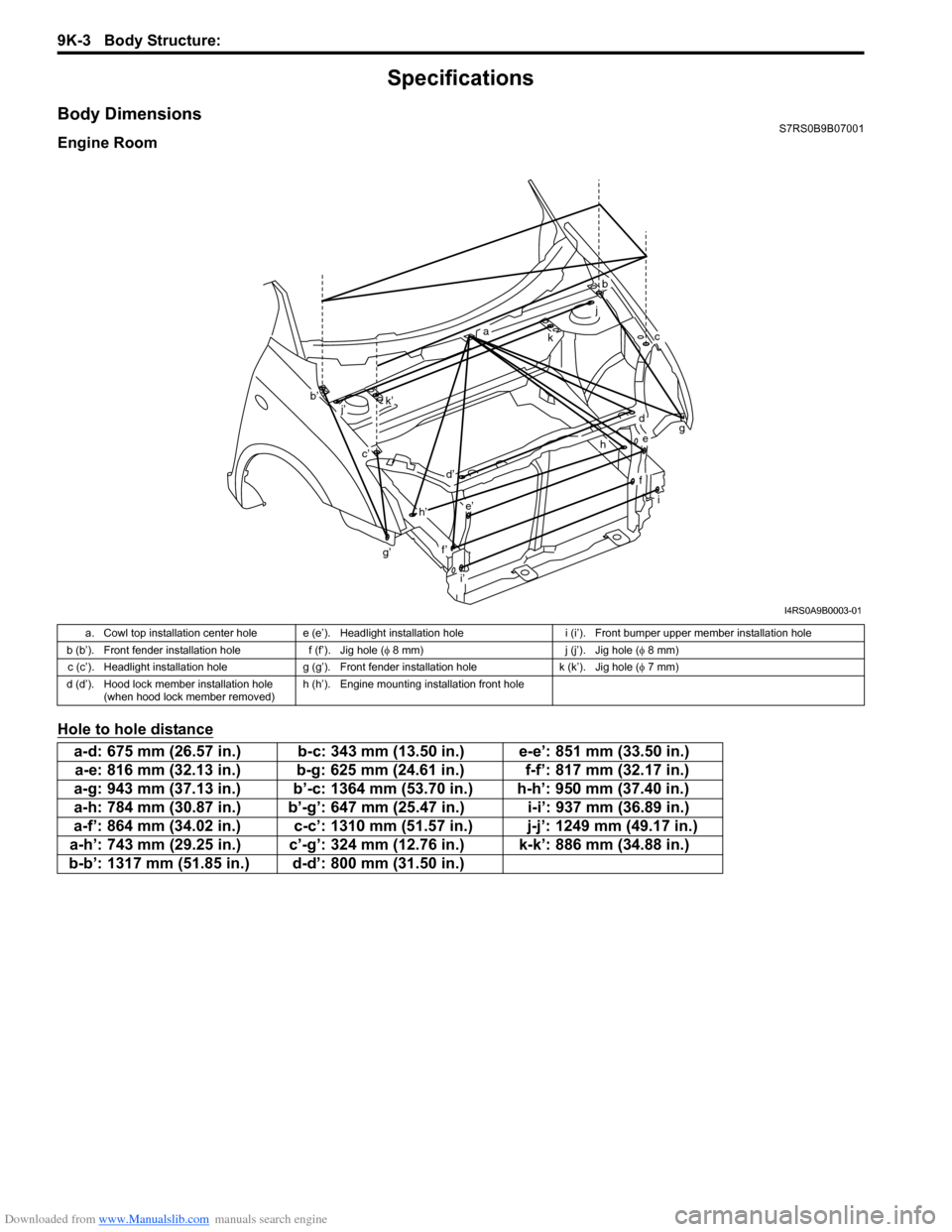
Specifications
Body DimensionsS7RS0B9B07001
Engine Room
Hole to hole distance
g’
b
ckg
i
a
b’
c’
d
d’
e
e’
f’
f
h
h’
i’ j
k’
j’
I4RS0A9B0003-01
a. Cowl top installation center hole e (e’). Headlight installation hole i (i’). Front bumper upper member installation hole
b (b’). Front fender installation hole f (f’). Jig hole (φ 8 mm) j (j’). Jig hole (φ 8 mm)
c (c’). Headlight installation hole g (g’). Front fender installation hole k (k’). Jig hole (φ 7 mm)
d (d’). Hood lock member installation hole (when hood lock member removed) h (h’). Engine mounting installation front hole
a-d: 675 mm (26.57 in.) b-c: 343 mm (13.50 in.) e-e’: 851 mm (33.50 in.)
a-e: 816 mm (32.13 in.) b-g: 625 mm (24.61 in.) f-f’: 817 mm (32.17 in.)
a-g: 943 mm (37.13 in.) b’-c: 1364 mm (53.70 in.) h-h’: 950 mm (37.40 in.)
a-h: 784 mm (30.87 in.) b’-g’: 647 mm (25.47 in.) i-i’: 937 mm (36.89 in.)
a-f’: 864 mm (34.02 in.) c-c’: 1310 mm (51.57 in.) j-j’: 1249 mm (49.17 in.)
a-h’: 743 mm (29.25 in.) c’-g’: 324 mm (12.76 in.) k-k’: 886 mm (34.88 in.)
b-b’: 1317 mm (51.85 in.) d-d’: 800 mm (31.50 in.)