Page 318 of 1496

Downloaded from www.Manualslib.com manuals search engine 1D-33 Engine Mechanical:
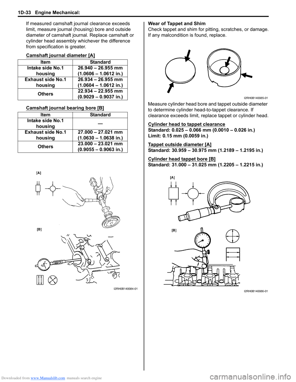
If measured camshaft journal clearance exceeds
limit, measure journal (housing) bore and outside
diameter of camshaft journal. Replace camshaft or
cylinder head assembly whichever the difference
from specification is greater.
Camshaft journal diameter [A]
Camshaft journal bearing bore [B]
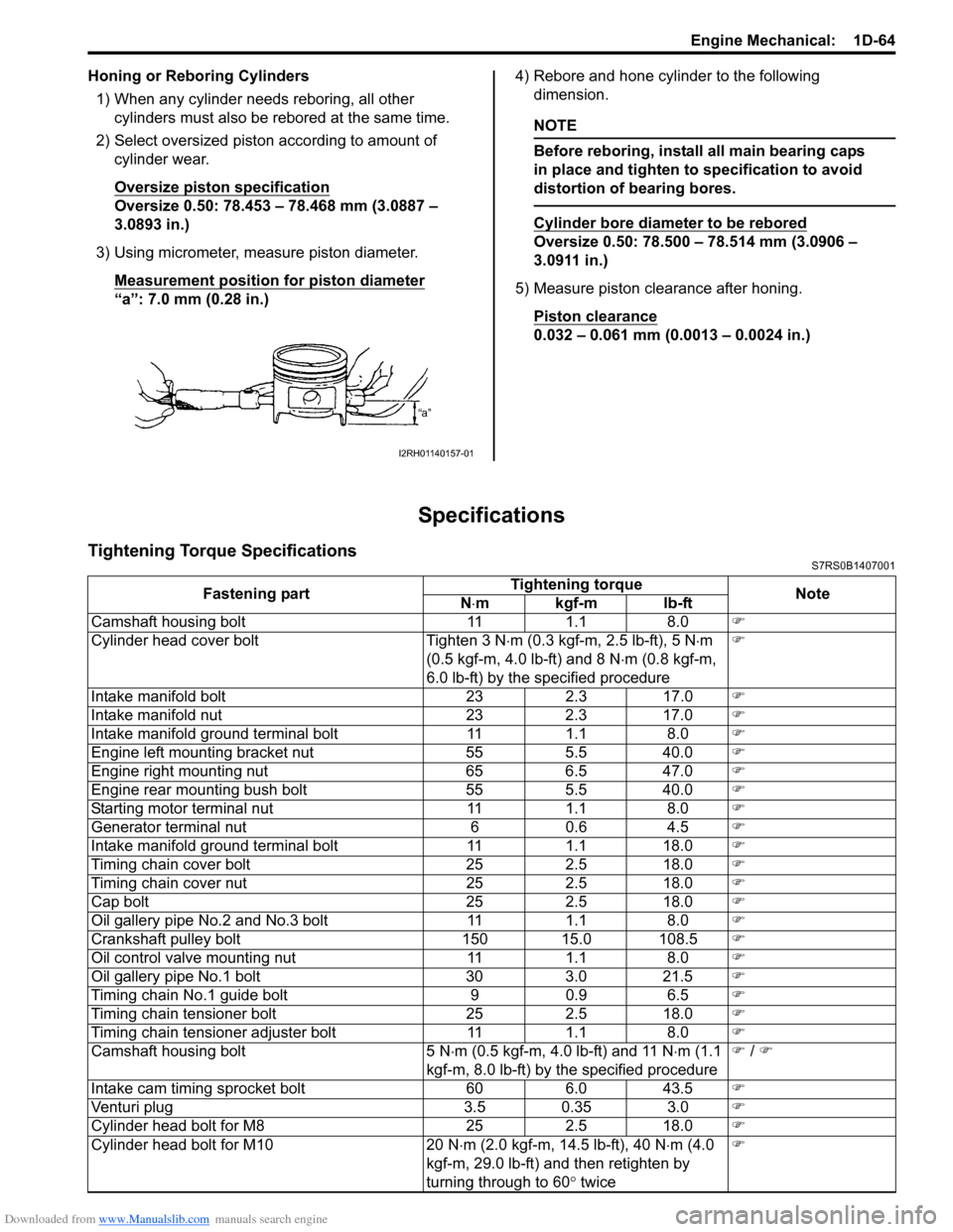
Wear of Tappet and Shim
Check tappet and shim for pitting, scratches, or damage.
If any malcondition is found, replace.
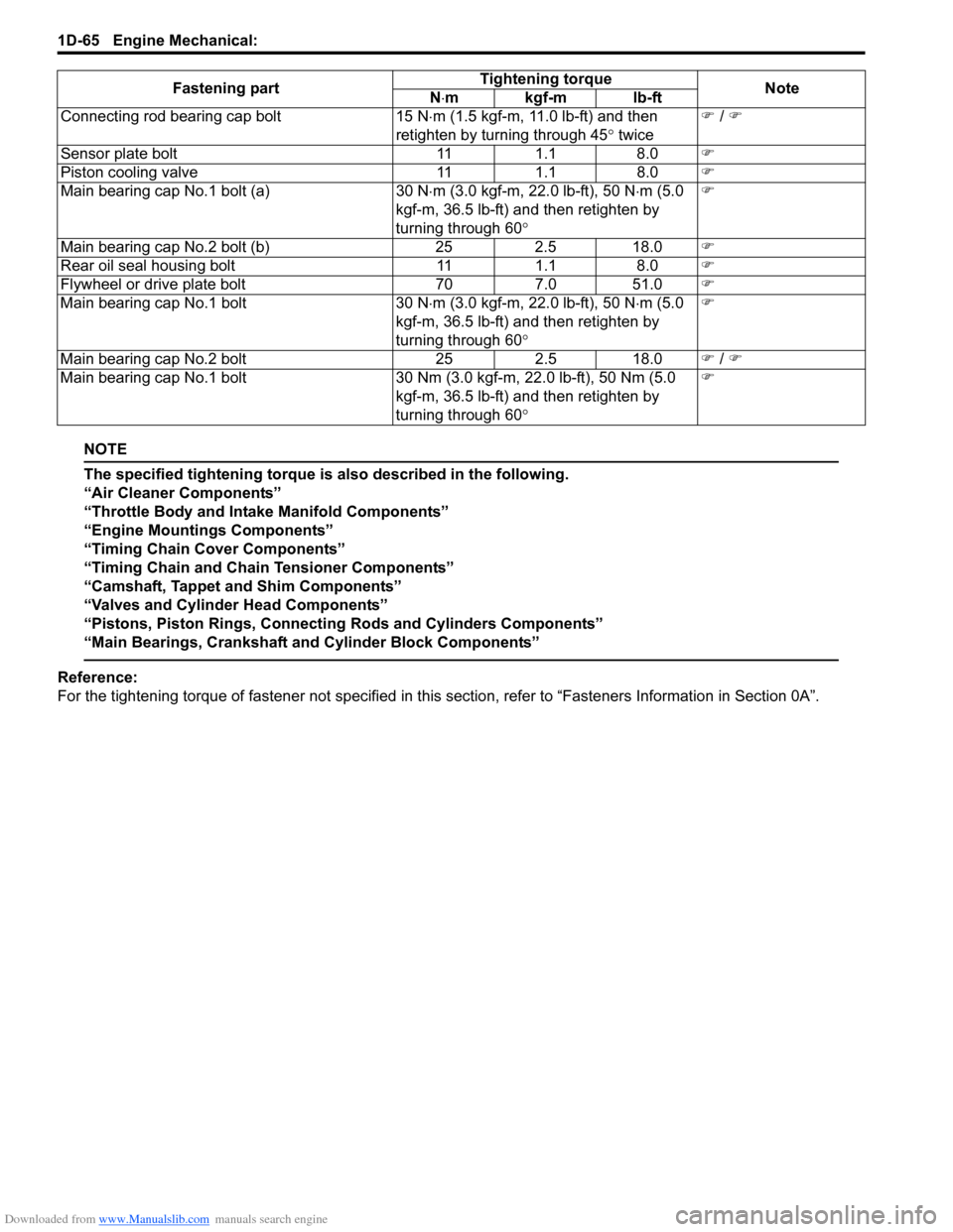
Measure cylinder head bore and tappet outside diameter
to determine cylinder head-to-tappet clearance. If
clearance exceeds limit, replace tappet or cylinder head.
Cylinder head to tappet clearance
Standard: 0.025 – 0.066 mm (0.0010 – 0.026 in.)
Limit: 0.15 mm (0.0059 in.)
Tappet outside diameter [A]
Standard: 30.959 – 30.975 mm (1.2189 – 1.2195 in.)
Cylinder head tappet bore [B]
Standard: 31.000 – 31.025 mm (1.2205 – 1.2215 in.)
Item Standard
Intake side No.1 housing 26.940 – 26.955 mm
(1.0606 – 1.0612 in.)
Exhaust side No.1 housing 26.934 – 26.955 mm
(1.0604 – 1.0612 in.)
Others 22.934 – 22.955 mm
(0.9029 – 0.9037 in.)
Item Standard
Intake side No.1 housing —
Exhaust side No.1 housing 27.000 – 27.021 mm
(1.0630 – 1.0638 in.)
Others 23.000 – 23.021 mm
(0.9055 – 0.9063 in.)
I2RH0B140084-01
I2RH0B140085-01
I2RH0B140086-01
Page 349 of 1496

Downloaded from www.Manualslib.com manuals search engine Engine Mechanical: 1D-64
Honing or Reboring Cylinders1) When any cylinder needs reboring, all other cylinders must also be rebored at the same time.
2) Select oversized piston according to amount of cylinder wear.
Oversize piston specification
Oversize 0.50: 78.453 – 78.468 mm (3.0887 –
3.0893 in.)
3) Using micrometer, measure piston diameter. Measurement position for piston diameter
“a”: 7.0 mm (0.28 in.) 4) Rebore and hone cylinder to the following
dimension.
NOTE
Before reboring, install all main bearing caps
in place and tighten to specification to avoid
distortion of bearing bores.
Cylinder bore diameter to be rebored
Oversize 0.50: 78.500 – 78.514 mm (3.0906 –
3.0911 in.)
5) Measure piston clearance after honing. Piston clearance
0.032 – 0.061 mm (0.0013 – 0.0024 in.)
Specifications
Tightening Torque SpecificationsS7RS0B1407001
I2RH01140157-01
Fastening part Tightening torque
Note
N ⋅mkgf-mlb-ft
Camshaft housing bolt 11 1.1 8.0 �)
Cylinder head cover bolt Tighten 3 N ⋅m (0.3 kgf-m, 2.5 lb-ft), 5 N ⋅m
(0.5 kgf-m, 4.0 lb-ft) and 8 N ⋅m (0.8 kgf-m,
6.0 lb-ft) by the specified procedure �)
Intake manifold bolt 23 2.3 17.0 �)
Intake manifold nut 23 2.3 17.0 �)
Intake manifold ground terminal bolt 11 1.1 8.0 �)
Engine left mounting bracket nut 55 5.5 40.0 �)
Engine right mounting nut 65 6.5 47.0 �)
Engine rear mounting bush bolt 55 5.5 40.0 �)
Starting motor terminal nut 11 1.1 8.0 �)
Generator terminal nut 6 0.6 4.5 �)
Intake manifold ground terminal bolt 11 1.1 18.0 �)
Timing chain cover bolt 25 2.5 18.0 �)
Timing chain cover nut 25 2.5 18.0 �)
Cap bolt 25 2.5 18.0 �)
Oil gallery pipe No.2 and No.3 bolt 11 1.1 8.0 �)
Crankshaft pulley bolt 150 15.0 108.5 �)
Oil control valve mounting nut 11 1.1 8.0 �)
Oil gallery pipe No.1 bolt 30 3.0 21.5 �)
Timing chain No.1 guide bolt 9 0.9 6.5 �)
Timing chain tensioner bolt 25 2.5 18.0 �)
Timing chain tensioner adjuster bolt 11 1.1 8.0 �)
Camshaft housing bolt 5 N ⋅m (0.5 kgf-m, 4.0 lb-ft) and 11 N ⋅m (1.1
kgf-m, 8.0 lb-ft) by the specified procedure �)
/ �)
Intake cam timing sprocket bolt 60 6.0 43.5 �)
Venturi plug 3.5 0.35 3.0 �)
Cylinder head bolt for M8 25 2.5 18.0 �)
Cylinder head bolt for M10 20 N ⋅m (2.0 kgf-m, 14.5 lb-ft), 40 N ⋅m (4.0
kgf-m, 29.0 lb-ft) and then retighten by
turning through to 60 ° twice �)
Page 350 of 1496

Downloaded from www.Manualslib.com manuals search engine 1D-65 Engine Mechanical:
NOTE
The specified tightening torque is also described in the following.
“Air Cleaner Components”
“Throttle Body and Intake Manifold Components”
“Engine Mountings Components”
“Timing Chain Cover Components”
“Timing Chain and Chain Tensioner Components”
“Camshaft, Tappet and Shim Components”
“Valves and Cylinder Head Components”
“Pistons, Piston Rings, Connecting Rods and Cylinders Components”
“Main Bearings, Crankshaft and Cylinder Block Components”
Reference:
For the tightening torque of fastener not specified in this section, refer to “Fasteners Information in Section 0A”.
Connecting rod bearing cap bolt
15 N⋅m (1.5 kgf-m, 11.0 lb-ft) and then
retighten by turning through 45 ° twice �)
/ �)
Sensor plate bolt 111.1 8.0 �)
Piston cooling valve 111.1 8.0 �)
Main bearing cap No.1 bolt (a) 30 N⋅m (3.0 kgf-m, 22.0 lb-ft), 50 N ⋅m (5.0
kgf-m, 36.5 lb-ft) and then retighten by
turning through 60 ° �)
Main bearing cap No.2 bolt (b) 252.5 18.0 �)
Rear oil seal housing bolt 111.1 8.0 �)
Flywheel or drive plate bolt 707.0 51.0 �)
Main bearing cap No.1 bolt 30 N⋅m (3.0 kgf-m, 22.0 lb-ft), 50 N ⋅m (5.0
kgf-m, 36.5 lb-ft) and then retighten by
turning through 60 ° �)
Main bearing cap No.2 bolt 252.5 18.0 �) / �)
Main bearing cap No.1 bolt 30 Nm (3.0 kgf-m, 22.0 lb-ft), 50 Nm (5.0
kgf-m, 36.5 lb-ft) and then retighten by
turning through 60 ° �)
Fastening part
Tightening torque
Note
N ⋅mkgf-mlb-ft