2006 SUZUKI SWIFT Vehicle speed
[x] Cancel search: Vehicle speedPage 956 of 1496
Downloaded from www.Manualslib.com manuals search engine 7B-8 Air Conditioning System: Manual Type
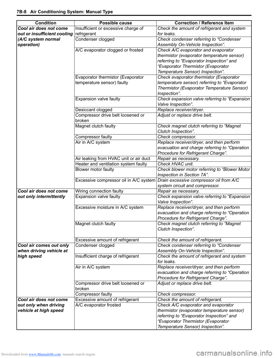
Cool air does not come
out or insufficient cooling
(A/C system normal
operation)Insufficient or excessive charge of
refrigerant
Check the amount of refrigerant and system
for leaks.
Condenser clogged Check condenser referring to “Condenser
Assembly On-Vehicle Inspection”.
A/C evaporator clogged or frosted Check A/C evaporator and evaporator
thermistor (evaporator temperature sensor)
referring to “Evaporator Inspection” and
“Evaporator Thermistor (Evaporator
Temperature Sensor) Inspection”.
Evaporator thermistor (Evaporator
temperature sensor) faulty Check evaporator thermistor (Evaporator
temperature sensor) referring to “Evaporator
Thermistor (Evaporator Temperature Sensor)
Inspection”.
Expansion valve faulty Check expansion valve referring to “Expansion
Valve Inspection”.
Desiccant clogged Replace receiver/dryer.
Compressor drive belt loosened or
broken Adjust or replace drive belt.
Magnet clutch faulty Check magnet clutch referring to “Magnet
Clutch Inspection”.
Compressor faulty Check compressor.
Air in A/C system Replace receiver/dryer, and then perform
evacuation and charge referring to “Operation
Procedure for Refrigerant Charge”.
Air leaking from HVAC unit or air duct Repair as necessary.
Heater and ventilation system faulty Check HVAC unit.
Blower motor faulty Check blower motor referring to “Blower Motor
Inspection in Section 7A”.
Excessive compressor oil in A/C system Drain excessive compressor oil from A/C
system circuit and compressor.
Cool air does not come
out only intermittently Wiring connection faulty
Repair as necessary.
Expansion valve faulty Check expansion valve referring to “Expansion
Valve Inspection”.
Excessive moisture in A/C system Replace receiver/dryer, and then perform
evacuation and charge referring to “Operation
Procedure for Refrigerant Charge”.
Magnet clutch faulty Check magnet clutch referring to “Magnet
Clutch Inspection”.
Excessive amount of refrigerant Check the amount of refrigerant.
Cool air comes out only
when driving vehicle at
high speed Condenser clogged
Check condenser referring to “Condenser
Assembly On-Vehicle Inspection”.
Insufficient charge of refrigerant Check the amount of refrigerant and system
for leaks.
Air in A/C system Replace receiver/dryer, and then perform
evacuation and charge referring to “Operation
Procedure for Refrigerant Charge”.
Compressor drive belt loosened or
broken Adjust or replace drive belt.
Compressor faulty Check compressor.
Cool air does not come
out only when driving
vehicle at high speed Excessive amount of refrigerant
Check the amount of refrigerant.
A/C evaporator frosted Check A/C evaporator and evaporator
thermistor (evaporator temperature sensor)
referring to “Evaporator Inspection” and
“Evaporator Thermistor (Evaporator
Temperature Sensor) Inspection”.
Condition Possible cause Correction / Reference Item
Page 958 of 1496

Downloaded from www.Manualslib.com manuals search engine 7B-10 Air Conditioning System: Manual Type
Abnormal Noise from Tension Pulley
Abnormal Noise from A/C Evaporator
Abnormal Noise from Blower Motor
A/C System Performance InspectionS7RS0B7214003
1) Confirm that vehicle and environmental conditions are as follows.
• Vehicle is put indoors.
• Ambient temperature is within 25 – 35 °C (77 – 95
° F).
• Relative humidity is within 30 – 70%.
• There is no wind indoors.
• HVAC unit is normal.
• Blower motor is normal.
• There is no air leakage from air ducts.
• Condenser fins are clean.
• Air filter in HVAC unit is not clogged with dirt and
dust.
• Battery voltage is about 12 V.
• Radiator cooling fan operates normally.
2) Make sure that high pressure valve (1) and low pressure valve (2) of manifold gauge are firmly
closed.
3) Connect high pressure charging hose (3) to high pressure service valve (5) on vehicle and low
pressure charging hose (4) to low pressure service
valve (6).
4) Bleed the air in charging hoses (3) and (4) by loosening their nuts respectively utilizing the
refrigerant pressure. When a hissing sound is heard,
immediately tighten nut.
CAUTION!
Do not connect high and low pressure
charging hoses in reverse.
Condition Possible cause Correction / Reference Item
Clattering noise is heard
from pulley Worn or damaged bearing
Replace tension pulley.
Pulley cranks upon
contact Cracked or loose bracket
Replace or retighten bracket.
ConditionPossible cause Correction / Reference Item
Whistling sound is heard
from A/C evaporator Depending on the combination of the
interior / exterior temperatures, engine
rpm and refrigerant pressure, the
refrigerant flowing out of the expansion
valve may, under certain conditions,
make a whistling sound At times, slightly decrea
sing refrigerant volume
may stop this noise.
Inspect expansion valve and replace if faulty.
Condition Possible cause Correction / Reference Item
Blower motor emits a
chirping sound in
proportion to its speed of
rotation Worn or damaged motor brushes or
commutator
Replace blower motor.
Fluttering noise or large
droning noise is heard
from blower motor Leaves or other debris introduced from
fresh air inlet to blower motor
Remove debris and make sure that the screen
at fresh air inlet is intact.
53
2
1
4 6
I4RS0A720006-01
Page 983 of 1496

Downloaded from www.Manualslib.com manuals search engine Air Conditioning System: Automatic Type 7B-35
Electronic Control System Location
NOTE
The figure shows left-hand steering vehicle. For right-hand steering vehicle, parts with (*) are installed
at the opposite side.
1
2
3 * 4 *
5
6 *
7 *
8 *
9 *
10 *
21
11
12 13
14
15161718
19
20
I5RS0C722001-01
1. ECT sensor
7. Blower motor13. AUTO switch19. MODE (air flow) selector
2. Outside air temperature sensor 8. Blower motor controller 14. Temperature selector 20. Blower speed selector
3. Sunload sensor 9. Temperature control actuator15. OFF switch21. HVAC control module
4. Air flow control actuator 10. Inside air temperature sensor 16. Air intake selector
5. Evaporator temperature sensor 11. Defroster switch 17. A/C switch
6. Air intake actuator 12. Display 18. Rear defogger switch
Page 988 of 1496
Downloaded from www.Manualslib.com manuals search engine 7B-40 Air Conditioning System: Automatic Type
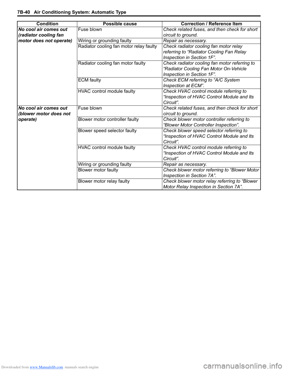
No cool air comes out
(radiator cooling fan
motor does not operate)Fuse blown
Check related fuses, and then check for short
circuit to ground.
Wiring or grounding faulty Repair as necessary.
Radiator cooling fan motor relay faulty Check radiator cooling fan motor relay
referring to “Radiator Cooling Fan Relay
Inspection in Section 1F”.
Radiator cooling fan motor faulty Check radiator cooling fan motor referring to
“Radiator Cooling Fan Motor On-Vehicle
Inspection in Section 1F”.
ECM faulty Check ECM referring to “A/C System
Inspection at ECM”.
HVAC control module faulty Check HVAC control module referring to
“Inspection of HVAC Control Module and Its
Circuit”.
No cool air comes out
(blower motor does not
operate) Fuse blown
Check related fuses, and then check for short
circuit to ground.
Blower motor controller faulty Check blower motor controller referring to
“Blower Motor Controller Inspection”.
Blower speed selector faulty Check blower speed selector referring to
“Inspection of HVAC Control Module and Its
Circuit”.
HVAC control module faulty Check HVAC control module referring to
“Inspection of HVAC Control Module and Its
Circuit”.
Wiring or grounding faulty Repair as necessary.
Blower motor faulty Check blower motor referring to “Blower Motor
Inspection in Section 7A”.
Blower motor relay faulty Check blower motor relay referring to “Blower
Motor Relay Inspection in Section 7A”.
Condition Possible cause Correction / Reference Item
Page 989 of 1496
Downloaded from www.Manualslib.com manuals search engine Air Conditioning System: Automatic Type 7B-41
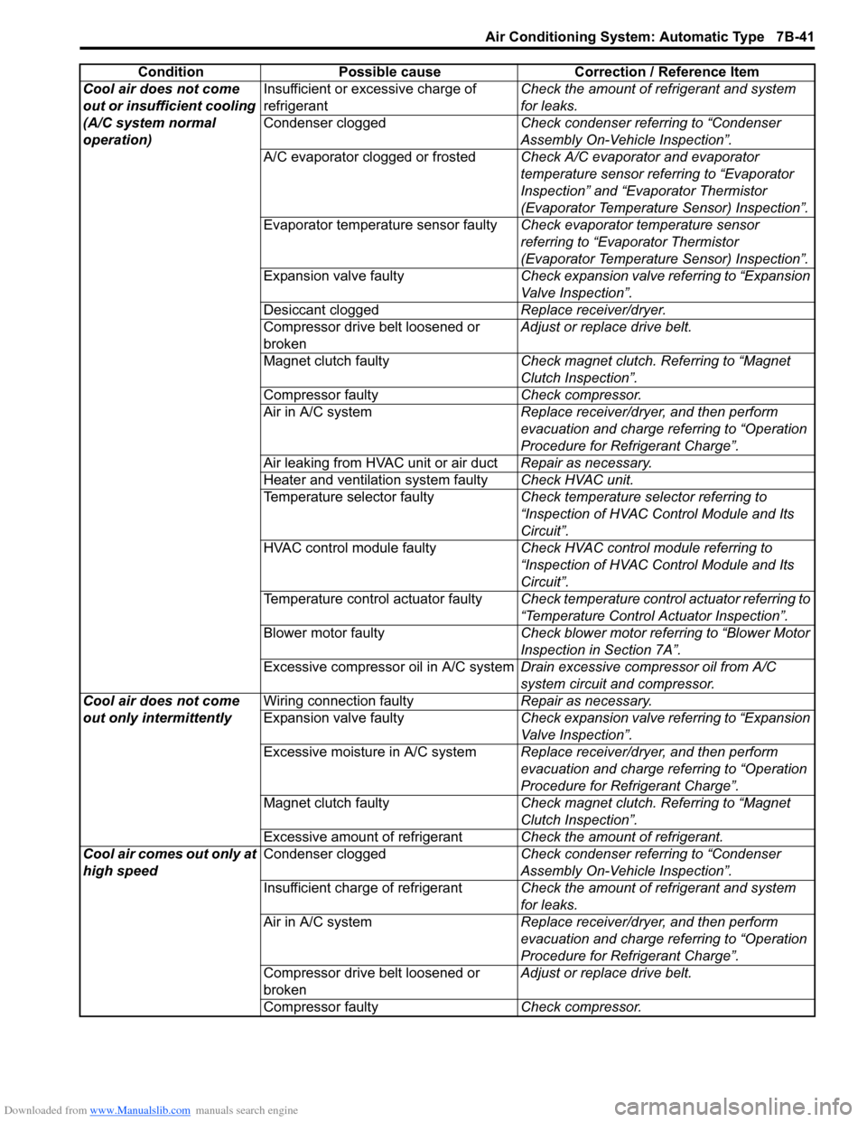
Cool air does not come
out or insufficient cooling
(A/C system normal
operation)Insufficient or excessive charge of
refrigerant
Check the amount of refrigerant and system
for leaks.
Condenser clogged Check condenser referring to “Condenser
Assembly On-Vehicle Inspection”.
A/C evaporator clogged or frosted Check A/C evaporator and evaporator
temperature sensor referring to “Evaporator
Inspection” and “Evaporator Thermistor
(Evaporator Temperature Sensor) Inspection”.
Evaporator temperature sensor faulty Check evaporator temperature sensor
referring to “Evaporator Thermistor
(Evaporator Temperature Sensor) Inspection”.
Expansion valve faulty Check expansion valve referring to “Expansion
Valve Inspection”.
Desiccant clogged Replace receiver/dryer.
Compressor drive belt loosened or
broken Adjust or replace drive belt.
Magnet clutch faulty Check magnet clutch. Referring to “Magnet
Clutch Inspection”.
Compressor faulty Check compressor.
Air in A/C system Replace receiver/dryer, and then perform
evacuation and charge referring to “Operation
Procedure for Refrigerant Charge”.
Air leaking from HVAC unit or air duct Repair as necessary.
Heater and ventilation system faulty Check HVAC unit.
Temperature selector faulty Check temperature selector referring to
“Inspection of HVAC Control Module and Its
Circuit”.
HVAC control module faulty Check HVAC control module referring to
“Inspection of HVAC Control Module and Its
Circuit”.
Temperature control actuator faulty Check temperature control actuator referring to
“Temperature Control Actuator Inspection”.
Blower motor faulty Check blower motor referring to “Blower Motor
Inspection in Section 7A”.
Excessive compressor oil in A/C system Drain excessive compressor oil from A/C
system circuit and compressor.
Cool air does not come
out only intermittently Wiring connection faulty
Repair as necessary.
Expansion valve faulty Check expansion valve referring to “Expansion
Valve Inspection”.
Excessive moisture in A/C system Replace receiver/dryer, and then perform
evacuation and charge referring to “Operation
Procedure for Refrigerant Charge”.
Magnet clutch faulty Check magnet clutch. Referring to “Magnet
Clutch Inspection”.
Excessive amount of refrigerant Check the amount of refrigerant.
Cool air comes out only at
high speed Condenser clogged
Check condenser referring to “Condenser
Assembly On-Vehicle Inspection”.
Insufficient charge of refrigerant Check the amount of refrigerant and system
for leaks.
Air in A/C system Replace receiver/dryer, and then perform
evacuation and charge referring to “Operation
Procedure for Refrigerant Charge”.
Compressor drive belt loosened or
broken Adjust or replace drive belt.
Compressor faulty Check compressor.
Condition Possible cause Correction / Reference Item
Page 992 of 1496
Downloaded from www.Manualslib.com manuals search engine 7B-44 Air Conditioning System: Automatic Type
3) Light over sunload sensor vertically with an incandescent lamp approximately 100 W apart from
about 100 mm (3.94 in.).
NOTE
If sunload sensor is not lighted over with an
incandescent lamp, DTC B1504 is detected
as current DTC even though there is not any
malfunction.
4) Turn ignition switch to ON position.
5) Erase DTC according to instructions displayed on SUZUKI scan tool.
NOTE
To know how to use SUZUKI scan tool, refer
to operator’s manual for SUZUKI scan tool.
6) After completing the clearance, turn ignition switch to OFF position, and then di sconnect SUZUKI scan
tool from DLC.
Not Using SUZUKI Scan Tool 1) Turn ignition switch to ON position.
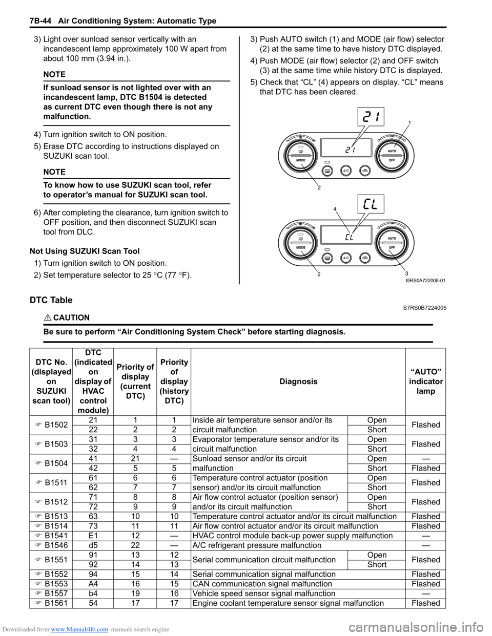
2) Set temperature selector to 25 °C (77 °F). 3) Push AUTO switch (1) and
MODE (air flow) selector
(2) at the same time to have history DTC displayed.
4) Push MODE (air flow) selector (2) and OFF switch (3) at the same time while history DTC is displayed.
5) Check that “CL” (4) appears on display. “CL” means that DTC has been cleared.
DTC TableS7RS0B7224005
CAUTION!
Be sure to perform “Air Conditioning Sy stem Check” before starting diagnosis.
1
2
3
2
4
I5RS0A722008-01
DTC No.
(displayed on
SUZUKI
scan tool) DTC
(indicated on
display of HVAC
control
module) Priority of
display
(current DTC) Priority
of
display
(history DTC) Diagnosis
“AUTO”
indicator lamp
�) B1502 21 1 1 Inside air temperature sensor and/or its
circuit malfunction Open
Flashed
22 2 2 Short
�) B1503 31 3 3 Evaporator temperature sensor and/or its
circuit malfunction Open
Flashed
32 4 4 Short
�) B1504 41 21 — Sunload sensor and/or its circuit
malfunction Open —
42 5 5 Short Flashed
�) B1511 61 6 6 Temperature control actuator (position
sensor) and/or its circuit malfunction Open
Flashed
62 7 7 Short
�) B1512 71 8 8 Air flow control actuator (position sensor)
and/or its circuit malfunction Open
Flashed
72 9 9 Short
�) B1513 63 10 10 Temperature control actuator and/or its circuit malfunction Flashed
�) B1514 73 11 11 Air flow control actuator and/or its circuit malfunction Flashed
�) B1541 E1 12 — HVAC control module back-up power supply malfunction —
�) B1546 d5 22 — A/C refrigerant pressure malfunction —
�) B1551 91 13 12
Serial communication circuit malfunction Open
Flashed
92 14 13 Short
�) B1552 94 15 14 Serial communication signal malfunction Flashed
�) B1553 A4 16 15 CAN communication signal malfunction Flashed
�) B1557 b4 19 16 Vehicle speed sensor signal malfunction —
�) B1561 54 17 17 Engine coolant temperature sensor signal malfunction Flashed
Page 993 of 1496
Downloaded from www.Manualslib.com manuals search engine Air Conditioning System: Automatic Type 7B-45
NOTE
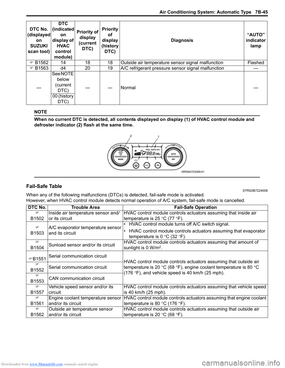
When no current DTC is detected, all contents displayed on display (1) of HVAC control module and
defroster indicator (2) flash at the same time.
Fail-Safe TableS7RS0B7224006
When any of the following malfunctions (DTCs) is detected, fail-safe mode is activated.
However, when HVAC control module detects normal ope ration of A/C system, fail-safe mode is cancelled.
�)
B1562 14 18 18 Outside air temperatur e sensor signal malfunction Flashed
�) B1563 d4 20 19 A/C refrigerant pressure sensor signal malfunction —
— See NOTE
below
(current DTC) ——Normal —
00 (history DTC)
DTC No.
(displayed on
SUZUKI
scan tool) DTC
(indicated on
display of HVAC
control
module) Priority of
display
(current DTC) Priority
of
display
(history DTC) Diagnosis
“AUTO”
indicator lamp
1
2
I5RS0A722009-01
DTC No.
Trouble Area Fail-Safe Operation
�)
B1502 Inside air temperature sensor and/
or its circuit HVAC control module controls actu
ators assuming that inside air
temperature is 25 ° C (77 °F).
�)
B1503 A/C evaporator temperature sensor
and its circuit • HVAC control module turn
s off A/C switch signal.
• HVAC control module controls actu ators assuming that evaporator
temperature is 0 ° C (32 °F).
�)
B1504 Sunload sensor and/or its circuit HVAC control module controls actu
ators assuming that amount of
sunlight is 0 W/m
2.
�) B1551 Serial communication circuit
HVAC control module controls actuators assuming that outside air
temperature is 20 ° C (68 °F), engine coolant temperature is 80 °C
(176 °F), and vehicle speed is 40 km/h (25 mph).
�)
B1552 Serial communication circuit
�)
B1553 CAN communication circuit
�)
B1557 Vehicle speed sensor and/or its
circuit HVAC control module controls act
uators assuming that vehicle speed
is 40 km/h (25 mph).
�)
B1561 Engine coolant temperature sensor
and/or its circuit HVAC control module controls act
uators assuming that engine coolant
temperature is 80 ° C (176 °F).
�)
B1562 Outside air temperature sensor
and/or its circuit HVAC control module controls actu
ators assuming that outside air
temperature is 20 ° C (68 °F).
Page 994 of 1496
Downloaded from www.Manualslib.com manuals search engine 7B-46 Air Conditioning System: Automatic Type
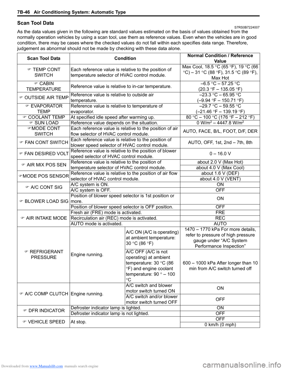
Scan Tool DataS7RS0B7224007
As the data values given in the following are standard values estimated on the basis of values obtained from the
normally operation vehicles by using a scan tool, use them as reference values. Even when the vehicles are in good
condition, there may be cases where the checked values do not fall within each specifies data range. Therefore,
judgement as abnormal should not be ma de by checking with these data alone.
Scan Tool Data Condition Normal Condition / Reference
Va l u e
�) TEMP CONT
SWITCH Each reference value is relative to the position of
temperature selector of HVAC control module. Max Cool, 18.5
°C (65 ° F), 19 °C (66
° C) – 31 °C (88 °F), 31.5 °C (89 °F),
Max Hot
�) CABIN
TEMPERATURE Reference value is relative to in-car temperature. –6.5
°C – 57.25 ° C
(20.3 °F – 135.05 °F)
�) OUTSIDE AIR TEMP Reference value is relative to outside air
temperature. –23.3
°C – 65.95 °C
(–9.94 °F – 150.71 °F)
�) EVAPORATOR
TEMP Reference value is relative to temperature of
evaporator. –29.7
°C – 59.55 °C
(–21.46 °F – 139.19 °F)
�) COOLANT TEMP At specified id le speed after warming up. 80 °C – 100 °C (176 ° F – 212 ° F)
�) SUN LOAD Reference value depends on the situation. 0 W/m
2 – 4447.8 W/m2
�)MODE CONT
SWITCH Each reference value is relative to the position of air
flow selector of HVAC control module.
AUTO, FACE, B/L, FOOT, D/F, DER
�) FAN CONT SWITCH Each reference value is relative to the position of
blower speed selector of HVAC control module. AUTO, OFF, 1st, 2nd – 7th, 8th
�) FAN DESIRED VOLT Reference value is relative to the position of blower
speed selector of HVAC control module. 0 – 16.0 V
�) AIR MIX POS SEN Reference value is relative to the position of
temperature selector of HVAC control module. about 2.0 V (Max Hot)
about 4.0 V (Max Cool)
�) MODE POS SENSOR Reference value is relative to the position of air flow
selector of HVAC control module. about 1.6 V (DEF)
about 4.0 V (VENT)
�) A/C CONT SIG A/C system is ON. ON
A/C system is OFF. OFF
�) BLOWER LOAD SIG Position of blower speed selector is 1st position or
more.
ON
Position of blower speed selector is OFF position. OFF
�) AIR INTAKE MODE Fresh air (FRE) mode is activated. FRE
Recirculation air (REC) mode is activated. REC
AUTO mode is activated. AUTO
�) REFRIGERANT
PRESSURE Engine running. A/C ON (A/C is operating)
at ambient temperature:
30
°C (86 °F) 1470 – 1770 kPa For more details,
refer to pressure of high pressure
gauge under “A/C System Performance Inspection”
A/C OFF (A/C is not
operating) at ambient
temperature: 30 °C (86
° F) and engine coolant
temperature: 90 ° – 100
° C 600 – 1000 kPa After longer than 10
min from A/C switch turned off
�) A/C COMP CLUTCH Engine running. A/C switch and blower
motor switch turned ON
ON
A/C switch and/or blower
motor switch turned OFF OFF
�) DFR INDICATOR Defroster indicator
lamp is lighted. ON
Defroster indicator la mp is not lighted. OFF
�) VEHICLE SPEED At stop. OFF
0 km/h (0 mph)