2006 SUZUKI SWIFT Torque spec
[x] Cancel search: Torque specPage 673 of 1496
Downloaded from www.Manualslib.com manuals search engine Automatic Transmission/Transaxle: 5A-29
Manual Road TestS7RS0B5104012
WARNING!
Carry out test in very little traffic area to prevent an accident.
Test requires 2 persons, a driver and a tester.
The purpose of this test is to judge whether causal factor of trouble which occurred in automatic transaxle is electrical
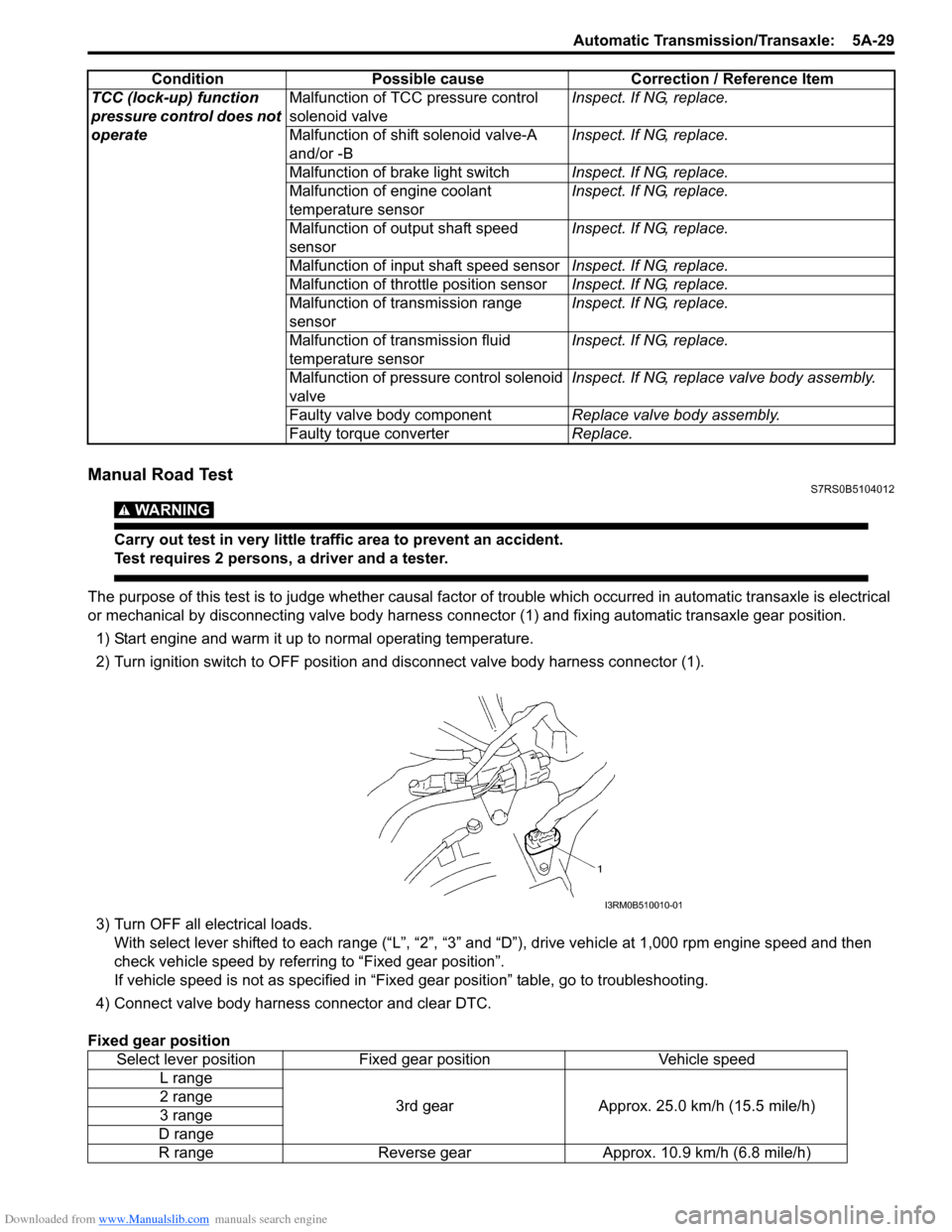
or mechanical by disconnecting valve body harness co nnector (1) and fixing automatic transaxle gear position.
1) Start engine and warm it up to normal operating temperature.
2) Turn ignition switch to OFF position and disconnect valve body harness connector (1).
3) Turn OFF all electrical loads. With select lever shifted to each ra nge (“L”, “2”, “3” and “D”), drive vehi cle at 1,000 rpm engine speed and then
check vehicle speed by referring to “Fixed gear position”.
If vehicle speed is not as specified in “Fix ed gear position” table, go to troubleshooting.
4) Connect valve body harness connector and clear DTC.
Fixed gear position TCC (lock-up) function
pressure control does not
operate
Malfunction of TCC pressure control
solenoid valve
Inspect. If NG, replace.
Malfunction of shif t solenoid valve-A
and/or -B Inspect. If NG, replace.
Malfunction of brake light switch Inspect. If NG, replace.
Malfunction of engine coolant
temperature sensor Inspect. If NG, replace.
Malfunction of output shaft speed
sensor Inspect. If NG, replace.
Malfunction of input shaft speed sensor Inspect. If NG, replace.
Malfunction of throttle position sensor Inspect. If NG, replace.
Malfunction of transmission range
sensor Inspect. If NG, replace.
Malfunction of transmission fluid
temperature sensor Inspect. If NG, replace.
Malfunction of pressure control solenoid
valve Inspect. If NG, replace valve body assembly.
Faulty valve body component Replace valve body assembly.
Faulty torque converter Replace.
Condition
Possible cause Correction / Reference Item
Select lever positionFixed gear position Vehicle speed
L range
3rd gearApprox. 25.0 km/h (15.5 mile/h)
2 range
3 range
D range
R range Reverse gear Approx. 10.9 km/h (6.8 mile/h)
I3RM0B510010-01
Page 675 of 1496
Downloaded from www.Manualslib.com manuals search engine Automatic Transmission/Transaxle: 5A-31
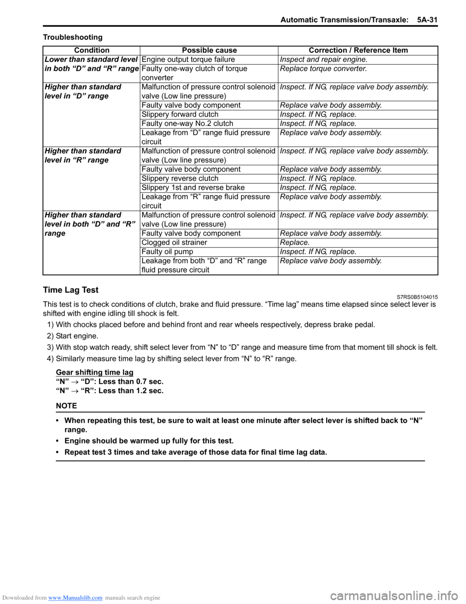
Troubleshooting
Time Lag TestS7RS0B5104015
This test is to check conditions of clutch, brake and fluid pressure. “Time lag” means time elapsed since select lever is
shifted with engine idling till shock is felt.
1) With chocks placed before and behind front and rear wheels respectively, depress brake pedal.
2) Start engine.
3) With stop watch ready, shift select lever from “N” to “D” range an d measure time from that moment till shock is felt.
4) Similarly measure time lag by shifting select lever from “N” to “R” range.
Gear shifting time lag
“N” → “D”: Less than 0.7 sec.
“N” → “R”: Less than 1.2 sec.
NOTE
• When repeating this test, be sure to wait at least one minute after select lever is shifted back to “N”
range.
• Engine should be warmed up fully for this test.
• Repeat test 3 times and take average of those data for final time lag data.
Condition Possible cause Correction / Reference Item
Lower than standard level
in both “D” and “R” range Engine output torque failure
Inspect and repair engine.
Faulty one-way clutch of torque
converter Replace torque converter.
Higher than standard
level in “D” range Malfunction of pressure control solenoid
valve (Low line pressure) Inspect. If NG, replace valve body assembly.
Faulty valve body component Replace valve body assembly.
Slippery forward clutch Inspect. If NG, replace.
Faulty one-way No.2 clutch Inspect. If NG, replace.
Leakage from “D” range fluid pressure
circuit Replace valve body assembly.
Higher than standard
level in “R” range Malfunction of pressure control solenoid
valve (Low line pressure) Inspect. If NG, replace valve body assembly.
Faulty valve body component Replace valve body assembly.
Slippery reverse clutch Inspect. If NG, replace.
Slippery 1st and reverse brake Inspect. If NG, replace.
Leakage from “R” range fluid pressure
circuit Replace valve body assembly.
Higher than standard
level in both “D” and “R”
range Malfunction of pressure control solenoid
valve (Low line pressure)
Inspect. If NG, replace valve body assembly.
Faulty valve body component Replace valve body assembly.
Clogged oil strainer Replace.
Faulty oil pump Inspect. If NG, replace.
Leakage from both “D” and “R” range
fluid pressure circuit Replace valve body assembly.
Page 684 of 1496
Downloaded from www.Manualslib.com manuals search engine 5A-40 Automatic Transmission/Transaxle:
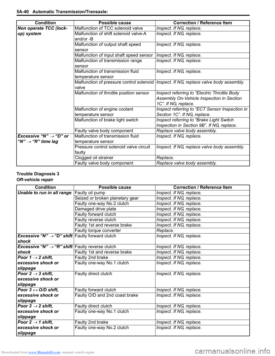
Trouble Diagnosis 3
Off-vehicle repairNon operate TCC (lock-
up) system
Malfunction of TCC solenoid valve
Inspect. If NG, replace.
Malfunction of shift solenoid valve-A
and/or -B Inspect. If NG, replace.
Malfunction of output shaft speed
sensor Inspect. If NG, replace.
Malfunction of input shaft speed sensor Inspect. If NG, replace.
Malfunction of transmission range
sensor Inspect. If NG, replace.
Malfunction of transmission fluid
temperature sensor Inspect. If NG, replace.
Malfunction of pressure control solenoid
valve Inspect. If NG, replace valve body assembly.
Malfunction of throttle position sensor Inspect referring to “Electric Throttle Body
Assembly On-Vehicle Inspection in Section
1C”. If NG, replace.
Malfunction of engine coolant
temperature sensor Inspect referring to “ECT Sensor Inspection in
Section 1C”. If NG, replace.
Malfunction of brake light switch Inspect referring to “Brake Light Switch
Inspection in Section 9B”. If NG, replace.
Faulty valve body component Replace valve body assembly.
Excessive “N”
→ “D” or
“N”
→ “R” time lag Malfunction of transmission fluid
temperature sensor Inspect. If NG, replace.
Pressure control solenoid valve circuit
faulty Inspect. If NG, replace valve body assembly.
Clogged oil strainer Replace.
Faulty valve body component Replace valve body assembly.
Condition Possible cause Correction / Reference Item
Condition
Possible cause Correction / Reference Item
Unable to run in all range Faulty oil pump Inspect. If NG, replace.
Seized or broken planetary gear Inspect. If NG, replace.
Faulty one-way No.2 clutch Inspect. If NG, replace.
Damaged drive plate Inspect. If NG, replace.
Faulty forward clutch Inspect. If NG, replace.
Faulty reverse clutch Inspect. If NG, replace.
Faulty 1st and reverse brake Inspect. If NG, replace.
Faulty torque converter Replace.
Excessive “N”
→ “D” shift
shock Faulty forward clutch
Inspect. If NG, replace.
Excessive “N”
→ “R” shift
shock Faulty reverse clutch
Inspect. If NG, replace.
Faulty 1st and reverse brake Inspect. If NG, replace.
Poor 1
→ 2 shift,
excessive shock or
slippage Faulty 2nd brake
Inspect. If NG, replace.
Faulty one-way No.1 clutch Inspect. If NG, replace.
Poor 2
→ 3 shift,
excessive shock or
slippage Faulty direct clutch
Inspect. If NG, replace.
Poor 3
↔ O/D shift,
excessive shock or
slippage Faulty forward clutch
Inspect. If NG, replace.
Faulty O/D and 2nd coast brake Inspect. If NG, replace.
Poor 3
→ 2 shift,
excessive shock or
slippage Faulty direct clutch
Inspect. If NG, replace.
Faulty one-way No.1 clutch Inspect. If NG, replace.
Poor 2
→ 1 shift,
excessive shock or
slippage Faulty 2nd brake
Inspect. If NG, replace.
Faulty one-way No.2 clutch Inspect. If NG, replace.
Page 685 of 1496
Downloaded from www.Manualslib.com manuals search engine Automatic Transmission/Transaxle: 5A-41
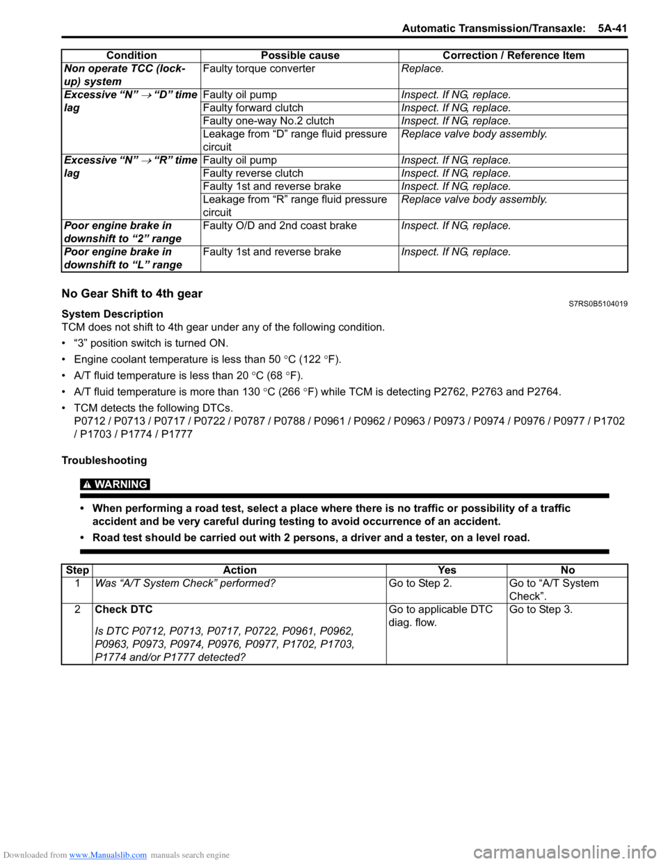
No Gear Shift to 4th gearS7RS0B5104019
System Description
TCM does not shift to 4th gear under any of the following condition.
• “3” position switch is turned ON.
• Engine coolant temperature is less than 50 °C (122 °F).
• A/T fluid temperature is less than 20 °C (68 °F).
• A/T fluid temperature is more than 130 °C (266 °F) while TCM is detecting P2762, P2763 and P2764.
• TCM detects the following DTCs. P0712 / P0713 / P0717 / P0722 / P0787 / P0788 / P0961 / P0962 / P0963 / P0973 / P0974 / P0976 / P0977 / P1702
/ P1703 / P1774 / P1777
Troubleshooting
WARNING!
• When performing a road test, select a place where there is no traffic or possibility of a traffic accident and be very careful during testing to avoid occurrence of an accident.
• Road test should be carried out with 2 persons, a driver and a tester, on a level road.
Non operate TCC (lock-
up) system Faulty torque converter
Replace.
Excessive “N”
→ “D” time
lag Faulty oil pump
Inspect. If NG, replace.
Faulty forward clutch Inspect. If NG, replace.
Faulty one-way No.2 clutch Inspect. If NG, replace.
Leakage from “D” range fluid pressure
circuit Replace valve body assembly.
Excessive “N”
→ “R” time
lag Faulty oil pump
Inspect. If NG, replace.
Faulty reverse clutch Inspect. If NG, replace.
Faulty 1st and reverse brake Inspect. If NG, replace.
Leakage from “R” range fluid pressure
circuit Replace valve body assembly.
Poor engine brake in
downshift to “2” range Faulty O/D and 2nd coast brake
Inspect. If NG, replace.
Poor engine brake in
downshift to “L” range Faulty 1st and reverse brake
Inspect. If NG, replace.
Condition Possible cause Correction / Reference Item
Step
Action YesNo
1 Was “A/T System Check” performed? Go to Step 2.Go to “A/T System
Check”.
2 Check DTC
Is DTC P0712, P0713, P0717, P0722, P0961, P0962,
P0963, P0973, P0974, P0976, P0977, P1702, P1703,
P1774 and/or P1777 detected? Go to applicable DTC
diag. flow.
Go to Step 3.
Page 719 of 1496
Downloaded from www.Manualslib.com manuals search engine Automatic Transmission/Transaxle: 5A-75
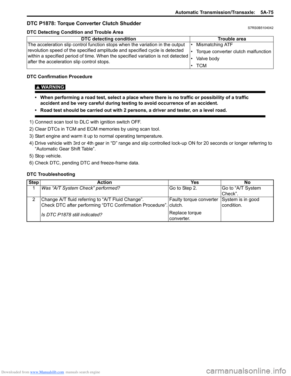
DTC P1878: Torque Converter Clutch ShudderS7RS0B5104042
DTC Detecting Condition and Trouble Area
DTC Confirmation Procedure
WARNING!
• When performing a road test, select a place where there is no traffic or possibility of a traffic accident and be very careful during testing to avoid occurrence of an accident.
• Road test should be carried out with 2 persons, a driver and tester, on a level road.
1) Connect scan tool to DLC with ignition switch OFF.
2) Clear DTCs in TCM and ECM memories by using scan tool.
3) Start engine and warm it up to normal operating temperature.
4) Drive vehicle with 3rd or 4th gear in “D” range and slip c ontrolled lock-up ON for 20 seconds or longer referring to
“Automatic Gear Shift Table”.
5) Stop vehicle.
6) Check DTC, pending DTC and freeze-frame data.
DTC Troubleshooting DTC detecting condition
Trouble area
The acceleration slip control function stops when the variation in the output
revolution speed of the specified amp litude and specified cycle is detected
within a specified period of time. When t he specified variation is not detected
after the acceleration slip control stops. • Mismatching ATF
• Torque converter clutch malfunction
• Valve body
•TCM
Step
Action YesNo
1 Was “A/T System Check” performed? Go to Step 2.Go to “A/T System
Check”.
2 Change A/T fluid referring to “A/T Fluid Change”. Check DTC after performing “DTC Confirmation Procedure”.
Is DTC P1878 still indicated? Faulty torque converter
clutch.
Replace torque
converter.System is in good
condition.
Page 720 of 1496
Downloaded from www.Manualslib.com manuals search engine 5A-76 Automatic Transmission/Transaxle:
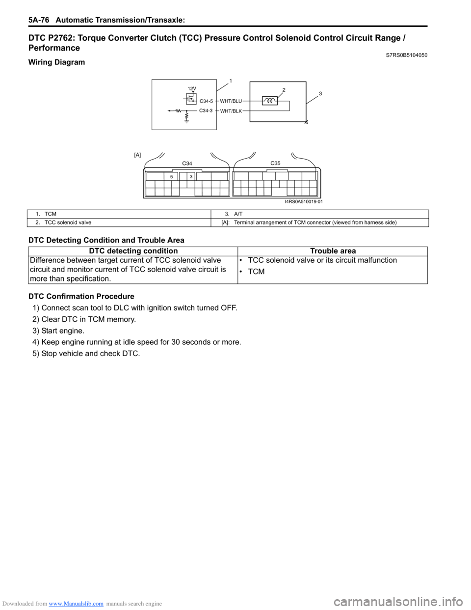
DTC P2762: Torque Converter Clutch (TCC) Pressure Control Solenoid Control Circuit Range /
Performance
S7RS0B5104050
Wiring Diagram
DTC Detecting Condition and Trouble Area
DTC Confirmation Procedure
1) Connect scan tool to DLC with ignition switch turned OFF.
2) Clear DTC in TCM memory.
3) Start engine.
4) Keep engine running at idle speed for 30 seconds or more.
5) Stop vehicle and check DTC.
12V
C34-5
C34-3
WHT/BLU
WHT/BLK
3
1
2
53
C34C35
[A]
I4RS0A510019-01
1. TCM
3. A/T
2. TCC solenoid valve [A]: Terminal arrangement of TCM connector (viewed from harness side)
DTC detecting conditionTrouble area
Difference between target current of TCC solenoid valve
circuit and monitor current of TCC solenoid valve circuit is
more than specification. • TCC solenoid valve or its circuit malfunction
•TCM
Page 734 of 1496
Downloaded from www.Manualslib.com manuals search engine 5A-90 Automatic Transmission/Transaxle:
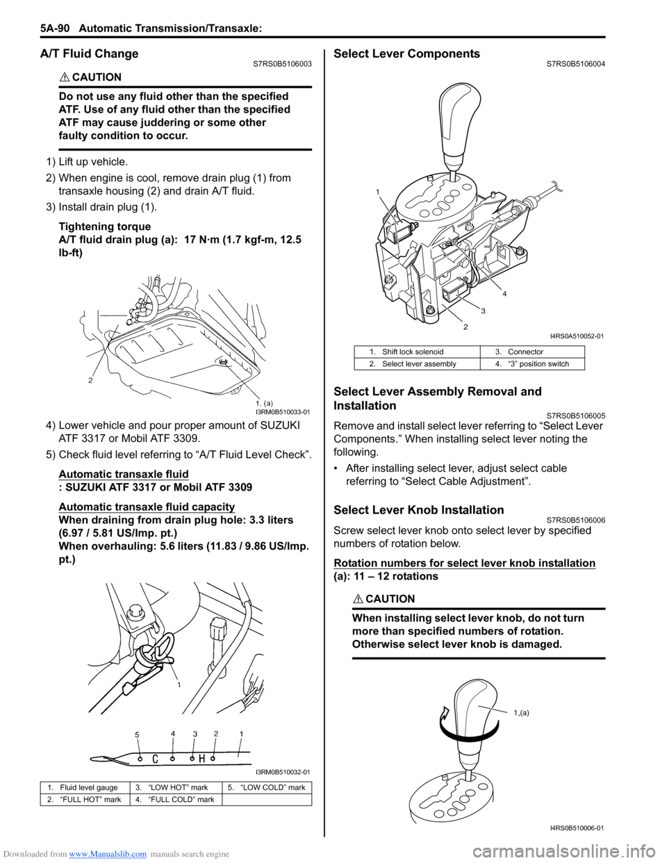
A/T Fluid ChangeS7RS0B5106003
CAUTION!
Do not use any fluid other than the specified
ATF. Use of any fluid other than the specified
ATF may cause juddering or some other
faulty condition to occur.
1) Lift up vehicle.
2) When engine is cool, remove drain plug (1) from
transaxle housing (2) and drain A/T fluid.
3) Install drain plug (1).
Tightening torque
A/T fluid drain plug (a): 17 N·m (1.7 kgf-m, 12.5
lb-ft)
4) Lower vehicle and pour proper amount of SUZUKI ATF 3317 or Mobil ATF 3309.
5) Check fluid level referring to “A/T Fluid Level Check”.
Automatic transaxle fluid
: SUZUKI ATF 3317 or Mobil ATF 3309
Automatic transaxle fluid capacity
When draining from drai n plug hole: 3.3 liters
(6.97 / 5.81 US/Imp. pt.)
When overhauling: 5.6 liters (11.83 / 9.86 US/Imp.
pt.)
Select Lever ComponentsS7RS0B5106004
Select Lever Assembly Removal and
Installation
S7RS0B5106005
Remove and install select leve r referring to “Select Lever
Components.” When installing select lever noting the
following.
• After installing select lever, adjust select cable referring to “Select Cable Adjustment”.
Select Lever Knob InstallationS7RS0B5106006
Screw select lever knob onto select lever by specified
numbers of rotation below.
Rotation numbers for select lever knob installation
(a): 11 – 12 rotations
CAUTION!
When installing select lever knob, do not turn
more than specified numbers of rotation.
Otherwise select lever knob is damaged.
1. Fluid level gauge 3. “LOW HOT” mark 5. “LOW COLD” mark
2. “FULL HOT” mark 4. “FULL COLD” mark
I3RM0B510033-01
I3RM0B510032-01
1. Shift lock solenoid 3. Connector
2. Select lever assembly 4. “3” position switch
1
23 4
I4RS0A510052-01
1,(a)
I4RS0B510006-01
Page 736 of 1496
Downloaded from www.Manualslib.com manuals search engine 5A-92 Automatic Transmission/Transaxle:
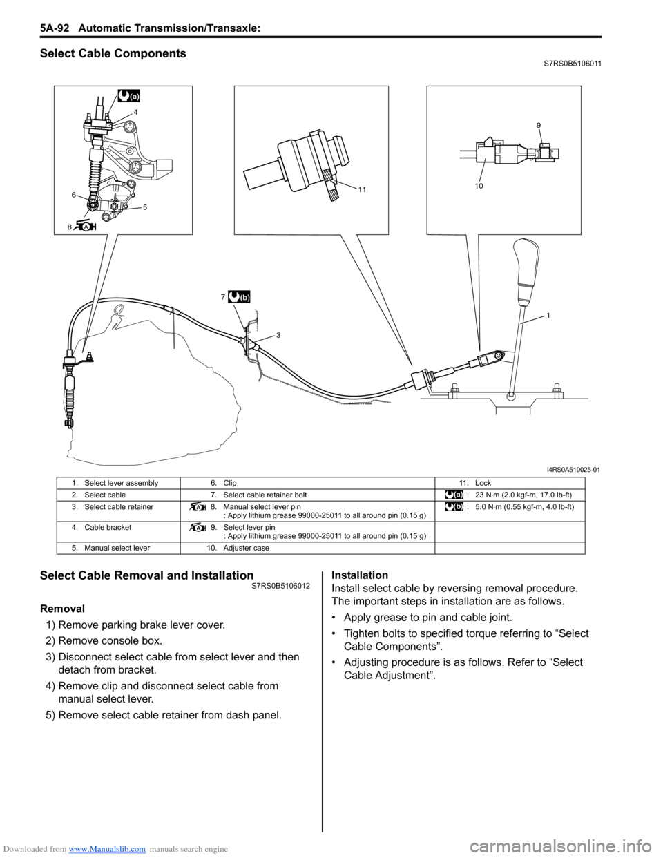
Select Cable ComponentsS7RS0B5106011
Select Cable Removal and InstallationS7RS0B5106012
Removal
1) Remove parking brake lever cover.
2) Remove console box.
3) Disconnect select cable from select lever and then detach from bracket.
4) Remove clip and disconnect select cable from manual select lever.
5) Remove select cable retainer from dash panel. Installation
Install select cable by reversing removal procedure.
The important steps in inst
allation are as follows.
• Apply grease to pin and cable joint.
• Tighten bolts to specified torque referring to “Select Cable Components”.
• Adjusting procedure is as follows. Refer to “Select Cable Adjustment”.
(a)
11
3
10
9
6
8 4
5
(b)
7
1
I4RS0A510025-01
1. Select lever assembly
6. Clip 11. Lock
2. Select cable 7. Select cable retainer bolt : 23 N⋅m (2.0 kgf-m, 17.0 lb-ft)
3. Select cable retainer 8. Manual select lever pin
: Apply lithium grease 99000-25011 to all around pin (0.15 g) :5.0 N
⋅m (0.55 kgf-m, 4.0 lb-ft)
4. Cable bracket 9. Select lever pin
: Apply lithium grease 99000-25011 to all around pin (0.15 g)
5. Manual select lever 10. Adjuster case