2006 SUZUKI SWIFT Control system
[x] Cancel search: Control systemPage 402 of 1496
Downloaded from www.Manualslib.com manuals search engine 1I-1 Starting System:
Engine
Starting System
Schematic and Routing Diagram
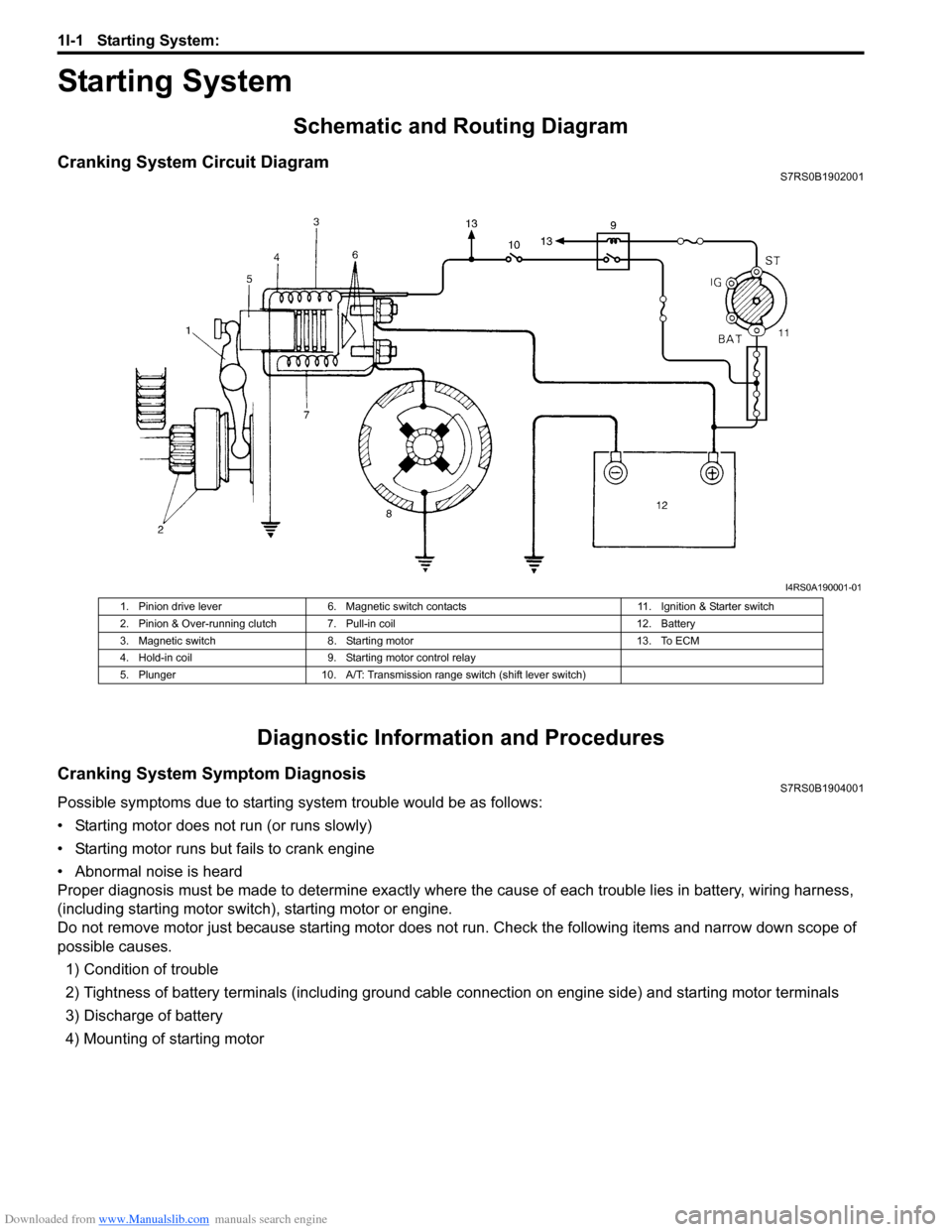
Cranking System Circuit DiagramS7RS0B1902001
Diagnostic Information and Procedures
Cranking System Symptom DiagnosisS7RS0B1904001
Possible symptoms due to starting system trouble would be as follows:
• Starting motor does not run (or runs slowly)
• Starting motor runs but fails to crank engine
• Abnormal noise is heard
Proper diagnosis must be made to determine exactly where the cause of each trouble lies in battery, wiring harness,
(including starting motor switch), starting motor or engine.
Do not remove motor just because starting motor does not run. Check the following items and narrow down scope of
possible causes.
1) Condition of trouble
2) Tightness of battery terminals (including ground cable connection on engine side) and starting motor terminals
3) Discharge of battery
4) Mounting of starting motor
I4RS0A190001-01
1. Pinion drive lever 6. Magnetic switch contacts 11. Ignition & Starter switch
2. Pinion & Over-running clutch 7. Pull-in coil 12. Battery
3. Magnetic switch 8. Starting motor 13. To ECM
4. Hold-in coil 9. Starting motor control relay
5. Plunger 10. A/T: Transmission range switch (shift lever switch)
Page 403 of 1496
Downloaded from www.Manualslib.com manuals search engine Starting System: 1I-2
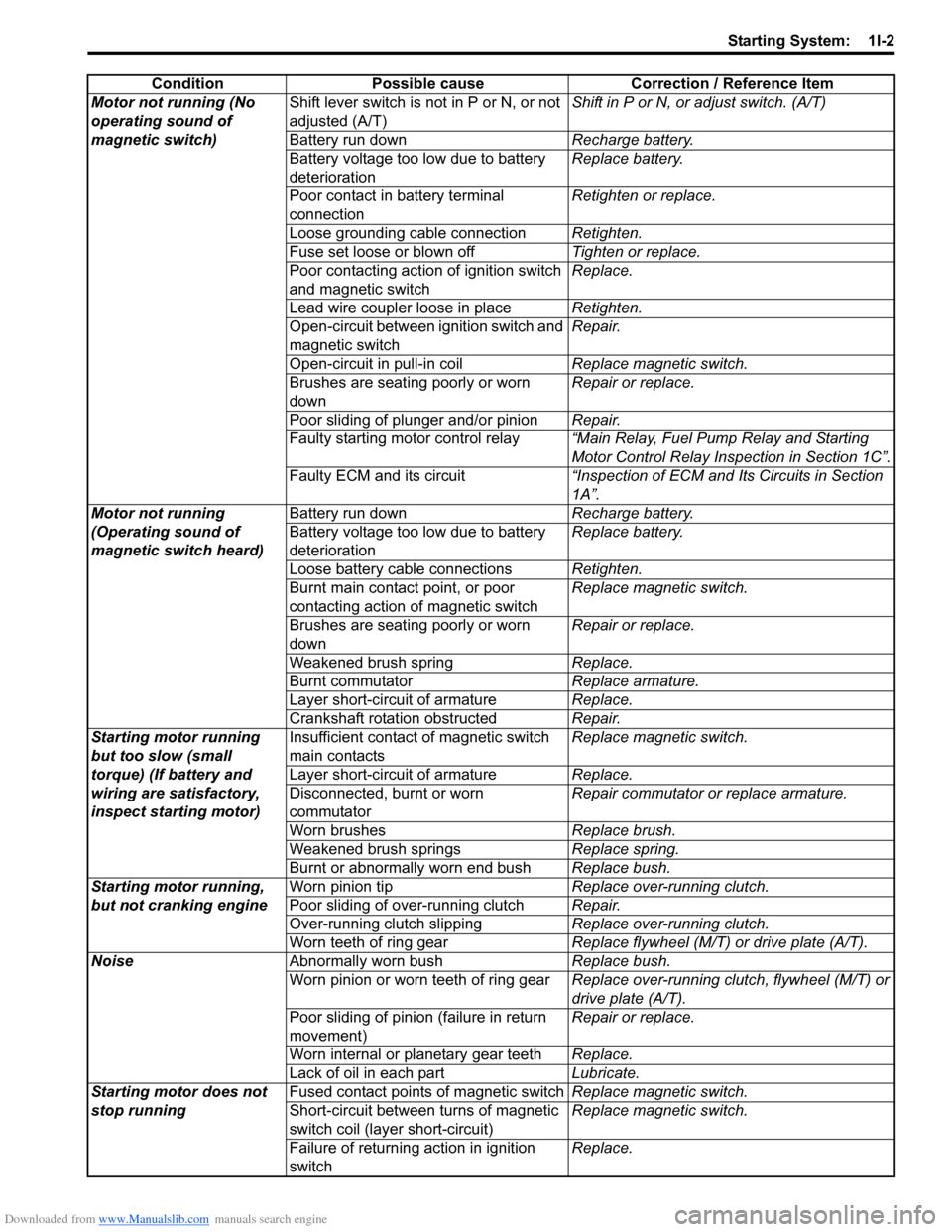
ConditionPossible cause Correction / Reference Item
Motor not running (No
operating sound of
magnetic switch) Shift lever switch is not in P or N, or not
adjusted (A/T)
Shift in P or N, or
adjust switch. (A/T)
Battery run down Recharge battery.
Battery voltage too low due to battery
deterioration Replace battery.
Poor contact in battery terminal
connection Retighten or replace.
Loose grounding cable connection Retighten.
Fuse set loose or blown off Tighten or replace.
Poor contacting action of ignition switch
and magnetic switch Replace.
Lead wire coupler loose in place Retighten.
Open-circuit between ignition switch and
magnetic switch Repair.
Open-circuit in pull-in coil Replace magnetic switch.
Brushes are seating poorly or worn
down Repair or replace.
Poor sliding of plunger and/or pinion Repair.
Faulty starting motor control relay “Main Relay, Fuel Pump Relay and Starting
Motor Control Relay Inspection in Section 1C”.
Faulty ECM and its circuit “Inspection of ECM and Its Circuits in Section
1A”.
Motor not running
(Operating sound of
magnetic switch heard) Battery run down
Recharge battery.
Battery voltage too low due to battery
deterioration Replace battery.
Loose battery cable connections Retighten.
Burnt main contact point, or poor
contacting action of magnetic switch Replace magnetic switch.
Brushes are seating poorly or worn
down Repair or replace.
Weakened brush spring Replace.
Burnt commutator Replace armature.
Layer short-circuit of armature Replace.
Crankshaft rotation obstructed Repair.
Starting motor running
but too slow (small
torque) (If battery and
wiring are satisfactory,
inspect starting motor) Insufficient contact
of magnetic switch
main contacts Replace magnetic switch.
Layer short-circuit of armature Replace.
Disconnected, burnt or worn
commutator Repair commutator or replace armature.
Worn brushes Replace brush.
Weakened brush springs Replace spring.
Burnt or abnormally worn end bush Replace bush.
Starting motor running,
but not cranking engine Worn pinion tip
Replace over-running clutch.
Poor sliding of over-running clutch Repair.
Over-running clutch slipping Replace over-running clutch.
Worn teeth of ring gear Replace flywheel (M/T) or drive plate (A/T).
Noise Abnormally worn bush Replace bush.
Worn pinion or worn teeth of ring gear Replace over-running clutch, flywheel (M/T) or
drive plate (A/T).
Poor sliding of pinion (failure in return
movement) Repair or replace.
Worn internal or planetary gear teeth Replace.
Lack of oil in each part Lubricate.
Starting motor does not
stop running Fused contact points of magnetic switch
Replace magnetic switch.
Short-circuit between turns of magnetic
switch coil (layer short-circuit) Replace magnetic switch.
Failure of returning action in ignition
switch Replace.
Page 405 of 1496

Downloaded from www.Manualslib.com manuals search engine Starting System: 1I-4
Repair Instructions
Starting Motor Dismounting and RemountingS7RS0B1906001
Dismounting1) Disconnect negative (–) battery lead at battery.
2) Disconnect magnetic switch lead wire (1) and battery cable (2) from starting motor terminals.
3) Detach shift & select control cable bracket from transaxle. (M/T model only)
4) Remove starting motor mount bolt (3) and nut (4).
5) Remove starting motor (5).
Remounting
Reverse the dismounting procedure noting the following.
• Tighten battery cable nut (6) to specified torque.
Tightening torque
Starting motor battery cable nut (a): 9.8 N·m (0.98 kgf-m, 7.0 lb-ft)
I4RS0A190002-01
: 9.8 N ⋅m (0.98 kgf-m, 7.0 lb-ft)
Page 413 of 1496
Downloaded from www.Manualslib.com manuals search engine Charging System: 1J-3
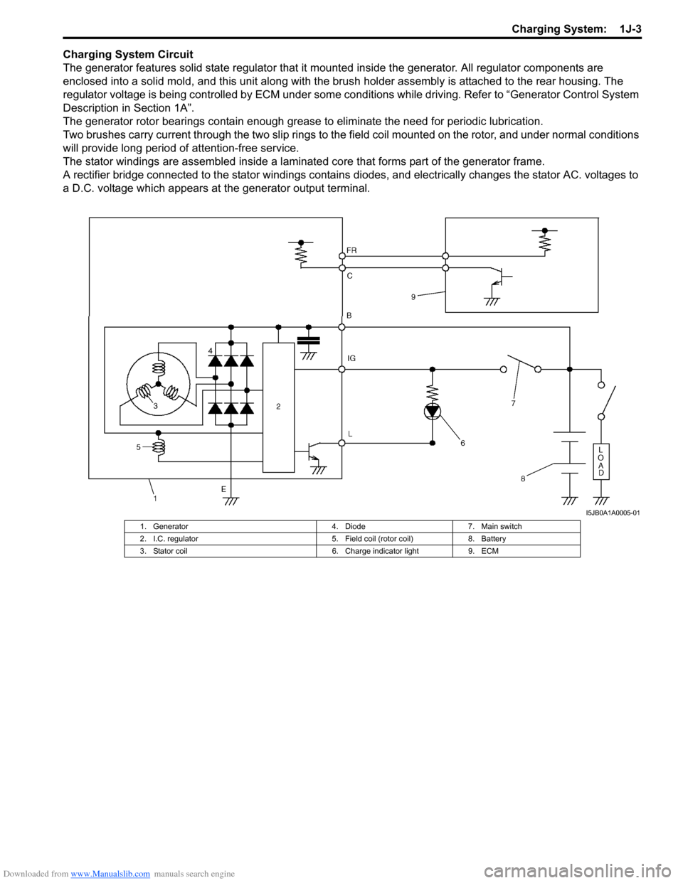
Charging System Circuit
The generator features solid state regulator that it mounted inside the generator. All regulator components are
enclosed into a solid mold, and this unit along with the brus h holder assembly is attached to the rear housing. The
regulator voltage is being controlled by ECM under some cond itions while driving. Refer to “Generator Control System
Description in Section 1A”.
The generator rotor bearings contain enough grease to eliminate the need for periodic lubrication.
Two brushes carry current through the two slip rings to the field coil mounted on the rotor, and under normal conditions
will provide long period of attention-free service.
The stator windings are assembled inside a laminate d core that forms part of the generator frame.
A rectifier bridge connected to the stator windings contains diodes, and electrically changes the stator AC. voltages to
a D.C. voltage which appears at the generator output terminal.
I5JB0A1A0005-01
1. Generator 4. Diode7. Main switch
2. I.C. regulator 5. Field coil (rotor coil)8. Battery
3. Stator coil 6. Charge indicator light9. ECM
Page 424 of 1496
Downloaded from www.Manualslib.com manuals search engine 1K-1 Exhaust System:
Engine
Exhaust System
General Description
Exhaust System DescriptionS7RS0B1B01001
The exhaust system consists of an exhaust manifold, three-way catalytic converter (TWC) in catalyst case, exhaust
pipes, a muffler and seals, gasket and etc.
The three-way catalytic converter is an emission control device added to the exhaust system to lower the levels of
Hydrocarbon (HC), Carbon Monoxide (CO), and Oxides of Nitrogen (NOx) pollutants in the exhaust gas.
Diagnostic Information and Procedures
Exhaust System CheckS7RS0B1B04001
WARNING!
To avoid the danger of being burned, do not touch the exhaust system when the system is hot. Any
service on the exhaust system should be performed when the system is cool.
At every interval of periodic maintenance service, and when vehicle is raised for other service, check exhaust system
as follows:
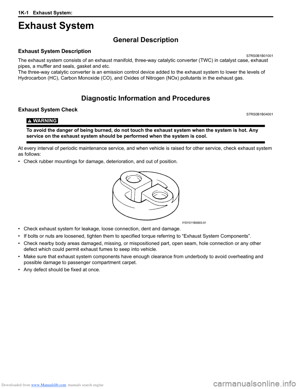
• Check rubber mountings for damage, deterioration, and out of position.
• Check exhaust system for leakage, loose connection, dent and damage.
• If bolts or nuts are loosened, tighten them to specified torque referring to “Exhaust System Components”.
• Check nearby body areas damaged, missing, or mispositio ned part, open seam, hole connection or any other
defect which could permit exhaust fumes to seep into vehicle.
• Make sure that exhaust system components have enough clearance from underbody to avoid overheating and
possible damage to passenger compartment carpet.
• Any defect should be fixed at once.
IYSY011B0003-01
Page 432 of 1496
Downloaded from www.Manualslib.com manuals search engine 2A-1 Suspension General Diagnosis:
Suspension
Suspension General Diagnosis
Diagnostic Information and Procedures
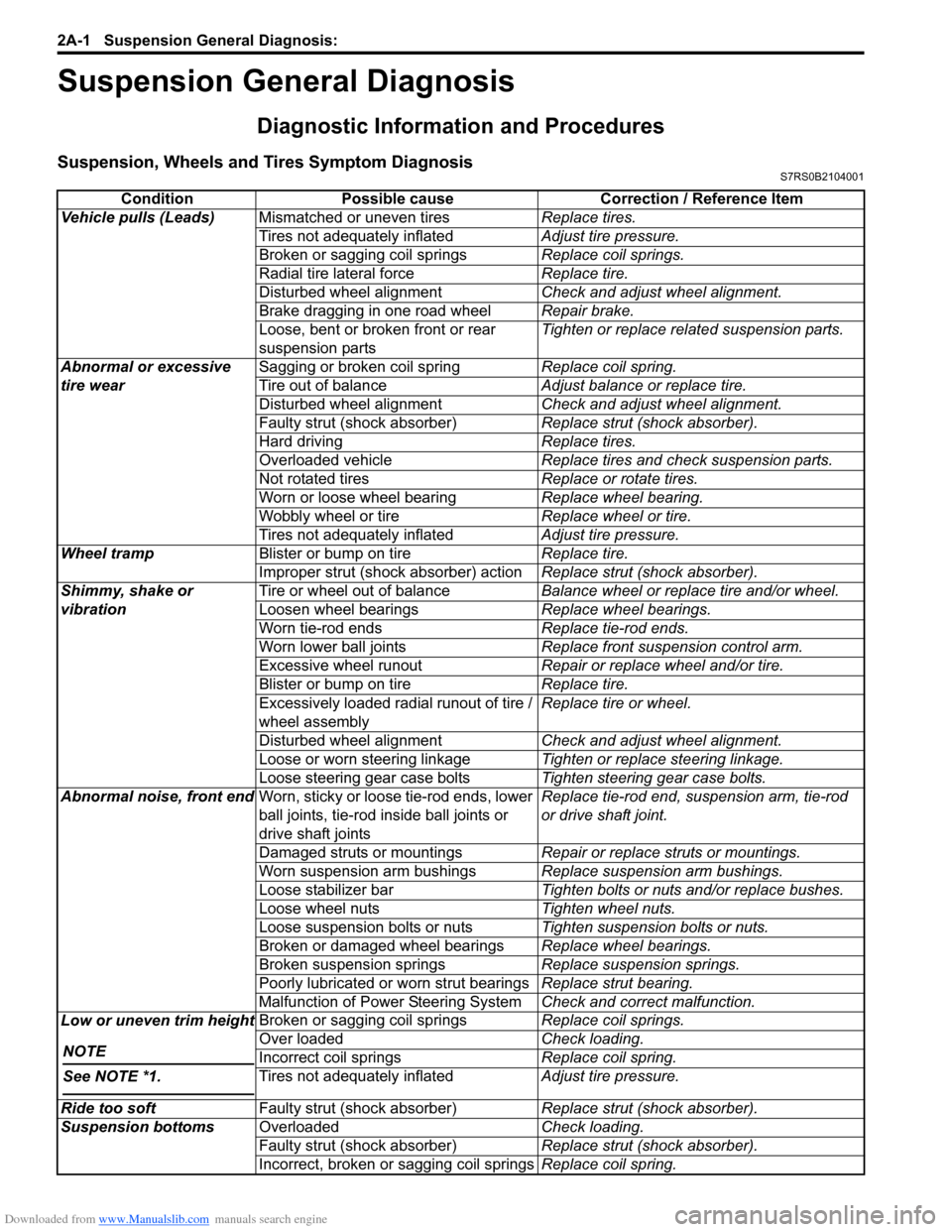
Suspension, Wheels and Tires Symptom DiagnosisS7RS0B2104001
ConditionPossible cause Correction / Reference Item
Vehicle pulls (Leads) Mismatched or uneven tires Replace tires.
Tires not adequately inflated Adjust tire pressure.
Broken or sagging coil springs Replace coil springs.
Radial tire lateral force Replace tire.
Disturbed wheel alignment Check and adjust wheel alignment.
Brake dragging in one road wheel Repair brake.
Loose, bent or broken front or rear
suspension parts Tighten or replace related suspension parts.
Abnormal or excessive
tire wear Sagging or broken coil spring
Replace coil spring.
Tire out of balance Adjust balance or replace tire.
Disturbed wheel alignment Check and adjust wheel alignment.
Faulty strut (shock absorber) Replace strut (shock absorber).
Hard driving Replace tires.
Overloaded vehicle Replace tires and check suspension parts.
Not rotated tires Replace or rotate tires.
Worn or loose wheel bearing Replace wheel bearing.
Wobbly wheel or tire Replace wheel or tire.
Tires not adequately inflated Adjust tire pressure.
Wheel tramp Blister or bump on tire Replace tire.
Improper strut (shock absorber) action Replace strut (shock absorber).
Shimmy, shake or
vibration Tire or wheel out of balance
Balance wheel or replace tire and/or wheel.
Loosen wheel bearings Replace wheel bearings.
Worn tie-rod ends Replace tie-rod ends.
Worn lower ball joints Replace front suspension control arm.
Excessive wheel runout Repair or replace wheel and/or tire.
Blister or bump on tire Replace tire.
Excessively loaded radial runout of tire /
wheel assembly Replace tire or wheel.
Disturbed wheel alignment Check and adjust wheel alignment.
Loose or worn steering linkage Tighten or replace steering linkage.
Loose steering gear case bolts Tighten steering gear case bolts.
Abnormal noise, front end Worn, sticky or loose tie-rod ends, lower
ball joints, tie-rod in side ball joints or
drive shaft joints Replace tie-rod end, su
spension arm, tie-rod
or drive shaft joint.
Damaged struts or mountings Repair or replace struts or mountings.
Worn suspension arm bushings Replace suspension arm bushings.
Loose stabilizer bar Tighten bolts or nuts and/or replace bushes.
Loose wheel nuts Tighten wheel nuts.
Loose suspension bolts or nuts Tighten suspension bolts or nuts.
Broken or damaged wheel bearings Replace wheel bearings.
Broken suspension springs Replace suspension springs.
Poorly lubricated or worn strut bearings Replace strut bearing.
Malfunction of Power Steering System Check and correct malfunction.
Low or uneven trim height
NOTE
See NOTE *1.
Broken or sagging coil springs Replace coil springs.
Over loaded Check loading.
Incorrect coil springs Replace coil spring.
Tires not adequately inflated Adjust tire pressure.
Ride too soft Faulty strut (shock absorber) Replace strut (shock absorber).
Suspension bottoms Overloaded Check loading.
Faulty strut (shock absorber) Replace strut (shock absorber).
Incorrect, broken or sagging coil springs Replace coil spring.
Page 448 of 1496
Downloaded from www.Manualslib.com manuals search engine 2B-15 Front Suspension:
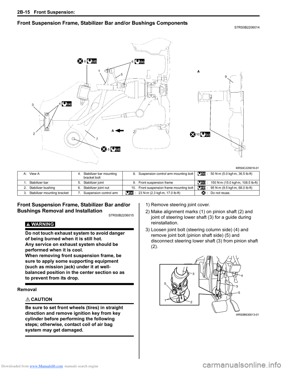
Front Suspension Frame, Stabilizer Bar and/or Bushings ComponentsS7RS0B2206014
Front Suspension Frame, Stabilizer Bar and/or
Bushings Removal and Installation
S7RS0B2206015
WARNING!
Do not touch exhaust system to avoid danger
of being burned when it is still hot.
Any service on exhaust system should be
performed when it is cool.
When removing front suspension frame, be
sure to apply some supporting equipment
(such as mission jack) under it at well-
balanced position in the center section so as
to prevent from its drop.
Removal
CAUTION!
Be sure to set front wheels (tires) in straight
direction and remove ignition key from key
cylinder before performing the following
steps; otherwise, contact coil of air bag
system may get damaged.
1) Remove steering joint cover.
2) Make alignment marks (1) on pinion shaft (2) and joint of steering lower shaft (3) for a guide during
reinstallation.
3) Loosen joint bolt (steering column side) (4) and remove joint bolt (pin ion shaft side) (5) and
disconnect steering lower shaft (3) from pinion shaft
(2).
I6RS0C220016-01
A: View A 4. Stabilizer bar mounting
bracket bolt 8. Suspension control arm mounting bolt : 50 N
⋅m (5.0 kgf-m, 36.5 lb-ft)
1. Stabilizer bar 5. Stabilizer joint 9. Front suspension frame : 150 N⋅m (15.0 kgf-m, 108.5 lb-ft)
2. Stabilizer bushing 6. Stabilizer joint nut10. Front suspension frame mounting bolt : 95 N ⋅m (9.5 kgf-m, 68.0 lb-ft)
3. Stabilizer mounting bracket 7. Suspension control arm : 23 N⋅m (2.3 kgf-m, 17.0 lb-ft) : Do not reuse.
5
2
1
5
34
3
I4RS0B630013-01
Page 495 of 1496

Downloaded from www.Manualslib.com manuals search engine Table of Contents 4- i
4
Section 4
CONTENTS
Brakes
Precautions ................................................. 4-1
Precautions............................................................. 4-1
Precautions for Brakes .......................................... 4-1
Brake Control System and Diagnosis ... 4A-1
Precautions........................................................... 4A-1Precautions on Brake .......................................... 4A-1
General Description ............................................. 4A-1 Brakes Construction ............................................ 4A-1
Brake Pedal Foot Protection System Construction ...................................................... 4A-2
Front Brake Hose / Pipe Co nstruction................. 4A-3
Rear Brake Hose / Pipe Construction ................. 4A-4
Diagnostic Information and Procedures ............ 4A-4 Brakes Diagnosis Note ....................................... 4A-4
Brakes Symptom Diagnosis ................................ 4A-5
Repair Instructions .............................................. 4A-7 Brake Pedal Components ................................... 4A-7
Brake Pedal Free Height Inspection ................... 4A-7
Brake Pedal Play Inspection ............................... 4A-7
Excessive Pedal Travel Inspection ..................... 4A-8
Brake Fluid Level Inspection ............................... 4A-8
Stop Light Switch Adjustment ............................. 4A-8
Air Bleeding of Brake System ............................. 4A-9
Front Brake Hose / Pipe Removal and Installation ....................................................... 4A-10
Rear Brake Hose / Pipe Removal and Installation ....................................................... 4A-10
Brake Hose and Pipe Inspection ....................... 4A-11
Master Cylinder Components............................ 4A-11
Master Cylinder Assembly Removal and Installation ....................................................... 4A-12
Master Cylinder Rese rvoir Removal and
Installation ....................................................... 4A-13
Master Cylinder Assemb ly Disassembly and
Assembly ........................................................ 4A-14
Master Cylinder Assembly Inspection ............... 4A-15
Brake Booster Components .............................. 4A-15
Booster Operation Inspection ........................... 4A-16
Brake Booster Removal and Installation ........... 4A-17
Brake Booster Inspection and Adjustment ........ 4A-18
Specifications ..................................................... 4A-18
Tightening Torque Specifications ...................... 4A-18
Special Tools and Equipmen t ........................... 4A-18 Recommended Service Material ....................... 4A-18
Front Brakes .......
..................................... 4B-1
Repair Instructions ........... ...................................4B-1
Front Disc Brake Components ............................ 4B-1
Front Disc Brake Pad On-Vehicle Inspection ...... 4B-2
Front Disc Brake Pad Removal and Installation ......................................................... 4B-2
Front Disc Brake Pad Inspection......................... 4B-3
Front Disc Brake Ca liper Removal and
Installation ......................................................... 4B-3
Front Disc Brake Caliper Disassembly and Assembly........................................................... 4B-4
Front Disc Brake Caliper In spection.................... 4B-6
Front Brake Disc Removal and Installation ......... 4B-6
Front Brake Disc Inspection ................................ 4B-7
Specifications .................... ...................................4B-8
Tightening Torque Specifications ........................ 4B-8
Special Tools and Equipmen t .............................4B-8
Recommended Service Material ......................... 4B-8
Special Tool ........................................................ 4B-8
Rear Brakes................... ........................... 4C-1
Repair Instructions ........... ...................................4C-1
Rear Disc Brake Components.............................4C-1
Rear Disc Brake Pad Removal and Installation .........................................................4C-2
Rear Disc Brake Caliper Removal and Installation .........................................................4C-3
Rear Disc Brake Pad Inspection .........................4C-6
Rear Disc Brake Caliper Disassembly and Assembly...........................................................4C-6
Rear Disc Brake Caliper Inspection ....................4C-8
Rear Flexible Hose Remova l and Installation .....4C-8
Rear Brake Disc Removal and Installation..........4C-9
Rear Brake Disc Inspection.................................4C-9
Specifications .................... .................................4C-10
Tightening Torque Specifications ......................4C-10
Special Tools and Equipmen t ...........................4C-11
Recommended Service Material .......................4C-11
Special Tool ......................................................4C-11
Parking Brake ................. ......................... 4D-1
General Description .............................................4D-1
Parking Brake Cable Construction ......................4D-1