2006 SUZUKI SWIFT Air flow
[x] Cancel search: Air flowPage 1189 of 1496
Downloaded from www.Manualslib.com manuals search engine Wiring Systems: 9A-18
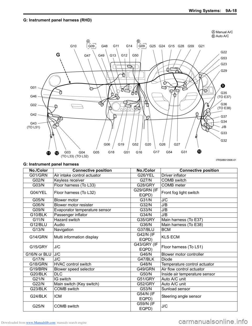
G: Instrument panel harness (RHD)
G: Instrument panel harness
J/B
9
10
G33
G32 G34 G35
(TO E37)
G36
(TO E38)
G31 G29
G23
G53
G22
G21
G28G59
G20G52G27
G54
G261112G03
(TO L33)G04
(TO L32)
G46
G01
G02
G42
G43
(TO L51) G10
G47
G11
G13G49
G14
G09G25 G24G15
G12G50
G48
G17
G16G51
G19
G18
G06
G05
G
G09
G37
A
BManual A/C
Auto A/C
AB
I7RS0B910906-01
No./Color Connective position No./ColorConnective position
G01/GRN Air intake control ac tuatorG26/YEL Driver inflator
G02/N Keyless receiver G27/N COMB switch
G03/N Floor harness (To L33) G28/GRY COMB meter
G04/YEL Floor harness (To L32) G29/GRN (IF
EQPD) Front fog light switch
G05/N Blower motor G31/N J/C
G06/N Blower motor resister G32/N J/B
G09/N Evaporator temperature sensor G33/N J/B
G10/BLK Passenger inflator G34/N J/B
G11/N Hazard switch G35/GRY Main harness (To E37)
G12/BLU Audio G36/N Main harness (To E38)
G13/N Navigation G37/BLU BCM
G14/GRN Multi information display G42/N (IF
EQPD) KLS ECM
G15/GRY J/C G43/GRY (IF
EQPD) Floor harness (To L51)
G16/N or BLU J/C G46/N Blower motor controller
G17/N J/C G47/BLK Diode
G18/GRN HVAC control switch G48/N Temperature control actuator
G19/BRN Blower speed selector G49/GRN Air flow control actuator
G20/BLK DLC G50/N Inside air temperature sensor
G21/N IG switch G51/GRY Auto A/C unit
G22/N Main switch (Key switch) G52/GRY Auto A/C unit
G23/BLK COMB switch G53/N Sunload sensor
G24/BLK ICM G54/N (IF
EQPD) Steering angle sensor
G25/N COMB switch G59/N (IF
EQPD) J/C
Page 1190 of 1496
Downloaded from www.Manualslib.com manuals search engine 9A-19 Wiring Systems:
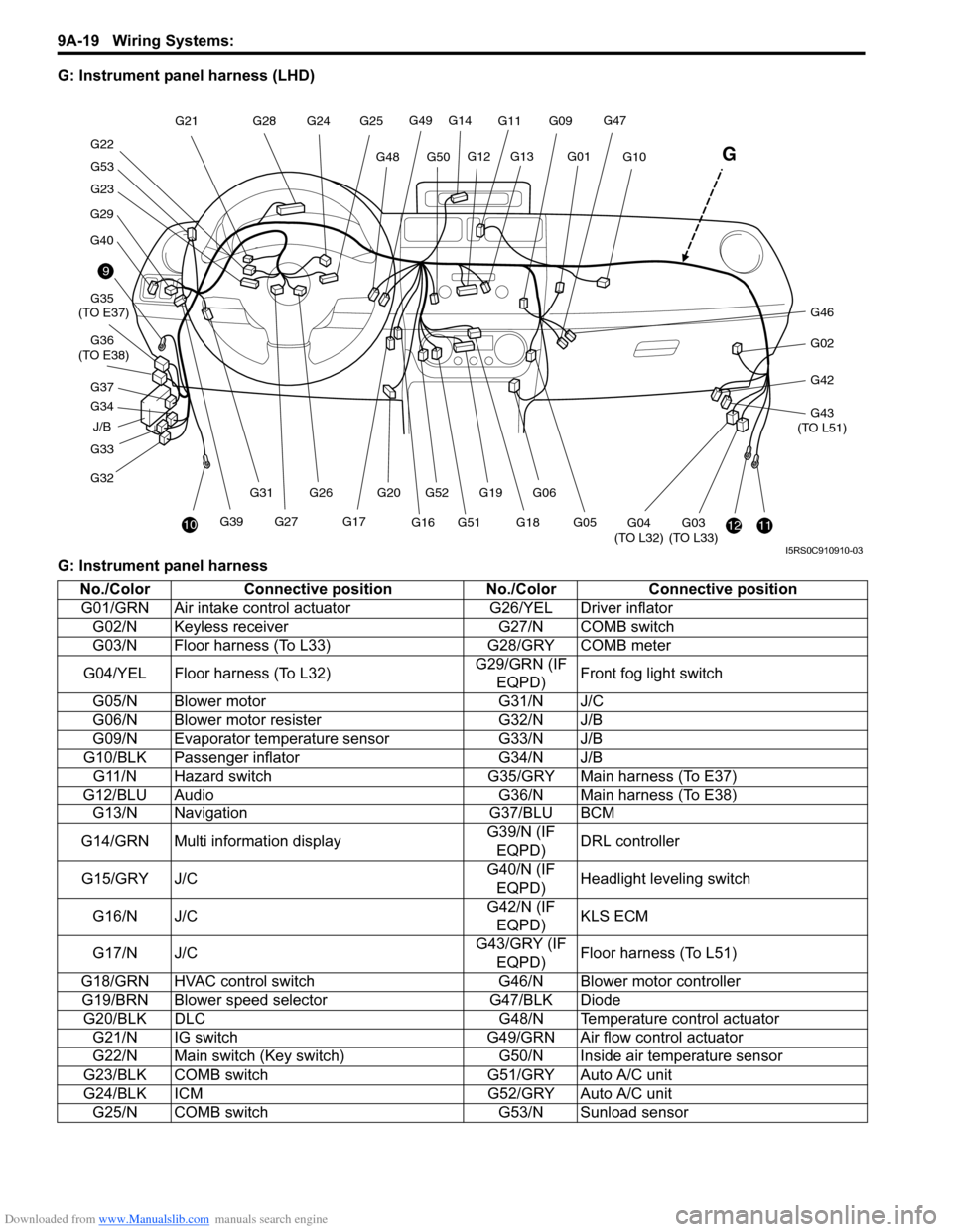
G: Instrument panel harness (LHD)
G: Instrument panel harness
J/B
9
10
G33
G32 G34 G35
(TO E37)
G36
(TO E38)
G29
G40
G23
G53
G22 G21
G28
G20G52
G27G39 G26
G31
1112G03
(TO L33)G04
(TO L32)
G46
G02
G42
G43
(TO L51)
G10
G47G11
G13G01
G14
G49
G50G48
G25
G24
G12
G17
G16G51G19
G18
G06
G05
G
G09
G37
I5RS0C910910-03
No./Color Connective position No./ColorConnective position
G01/GRN Air intake control ac tuatorG26/YEL Driver inflator
G02/N Keyless receiver G27/N COMB switch
G03/N Floor harness (To L33) G28/GRY COMB meter
G04/YEL Floor harness (To L32) G29/GRN (IF
EQPD) Front fog light switch
G05/N Blower motor G31/N J/C
G06/N Blower motor resister G32/N J/B
G09/N Evaporator temperature sensor G33/N J/B
G10/BLK Passenger inflator G34/N J/B
G11/N Hazard switch G35/GRY Main harness (To E37)
G12/BLU Audio G36/N Main harness (To E38)
G13/N Navigation G37/BLU BCM
G14/GRN Multi information display G39/N (IF
EQPD) DRL controller
G15/GRY J/C G40/N (IF
EQPD) Headlight leveling switch
G16/N J/C G42/N (IF
EQPD) KLS ECM
G17/N J/C G43/GRY (IF
EQPD) Floor harness (To L51)
G18/GRN HVAC control switch G46/N Blower motor controller
G19/BRN Blower speed selector G47/BLK Diode
G20/BLK DLC G48/N Temperature control actuator
G21/N IG switch G49/GRN Air flow control actuator
G22/N Main switch (Key switch) G50/N Inside air temperature sensor
G23/BLK COMB switch G51/GRY Auto A/C unit
G24/BLK ICM G52/GRY Auto A/C unit
G25/N COMB switch G53/N Sunload sensor
Page 1263 of 1496
Downloaded from www.Manualslib.com manuals search engine Wiring Systems: 9A-92
G091
2
346
1698G52 G51
G52 G52
G51 G51G52
1
3
7
G495
6
M
G48
M
2
31141413
341
M
2G46
5G33
WHT/RED
WHT/RED
BLK/WHT
GRY/REDGRY/BLUWHTWHT/BLUBRN/WHTBRN/YELWHT/BLKGRN
WHTYELWHTWHT/BLU
GRNGRNBLKGRNGRN
BLK/YELBLK/YEL
BLK/WHTGRYBLK/WHTBLU/RED
Blower motor controller
A/C
DiodeAutounit
Blower
motor
15A RADIO
Evaporator
temperature
sensor Air flow control
actuator
Temperature
control actuator
40
635
71 2
G47
G051
2 1
5V5V
5V5V 12V
12V
12V
J/B
J/B
G326
1 2
5
3
30A HTR
FAN
4
10A
38IG2
SIG
Blowermotorrelay
E39
7
G349
G15
J/C
912
A
A
BLK
11
A
BLKBLK
BLU
J/C
B BG16
B
G16
J/C
DDDD
G17
J/C
B
B
Individual circuit fuse box (No.1)
G502
1
PNK/BLK
Inside air
temperature
sensor
5V
I7RS0B910946-02
Page 1413 of 1496
Downloaded from www.Manualslib.com manuals search engine Body Electrical Control System: 10B-10
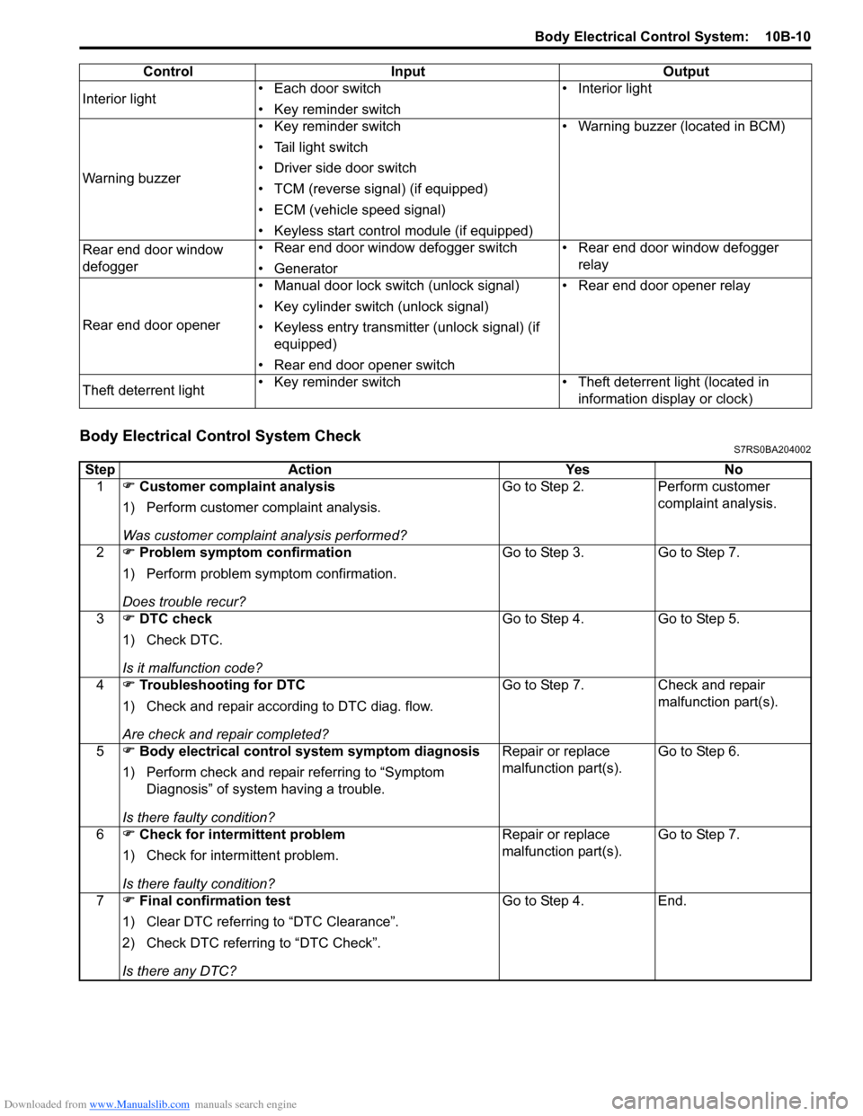
Body Electrical Control System CheckS7RS0BA204002
Interior light• Each door switch
• Key reminder switch • Interior light
Warning buzzer • Key reminder switch
• Tail light switch
• Driver side door switch
• TCM (reverse signal) (if equipped)
• ECM (vehicle speed signal)
• Keyless start control module (if equipped) • Warning buzzer (located in BCM)
Rear end door window
defogger • Rear end door window defogger switch
• Generator • Rear end door window defogger
relay
Rear end door opener • Manual door lock switch (unlock signal)
• Key cylinder switch (unlock signal)
• Keyless entry transmitter (unlock signal) (if
equipped)
• Rear end door opener switch • Rear end door opener relay
Theft deterrent light • Key reminder switch • Theft deterrent light (located in
information display or clock)
Control Input Output
Step
Action YesNo
1 �) Customer complaint analysis
1) Perform customer complaint analysis.
Was customer complaint analysis performed? Go to Step 2.
Perform customer
complaint analysis.
2 �) Problem symptom confirmation
1) Perform problem symptom confirmation.
Does trouble recur? Go to Step 3.
Go to Step 7.
3 �) DTC check
1) Check DTC.
Is it malfunction code? Go to Step 4.
Go to Step 5.
4 �) Troubleshooting for DTC
1) Check and repair according to DTC diag. flow.
Are check and repair completed? Go to Step 7.
Check and repair
malfunction part(s).
5 �) Body electrical control system symptom diagnosis
1) Perform check and repair referring to “Symptom Diagnosis” of system having a trouble.
Is there faulty condition? Repair or replace
malfunction part(s).
Go to Step 6.
6 �) Check for intermittent problem
1) Check for interm ittent problem.
Is there faulty condition? Repair or replace
malfunction part(s).
Go to Step 7.
7 �) Final confirmation test
1) Clear DTC referring to “DTC Clearance”.
2) Check DTC referring to “DTC Check”.
Is there any DTC? Go to Step 4.
End.
Page 1414 of 1496
Downloaded from www.Manualslib.com manuals search engine 10B-11 Body Electrical Control System:
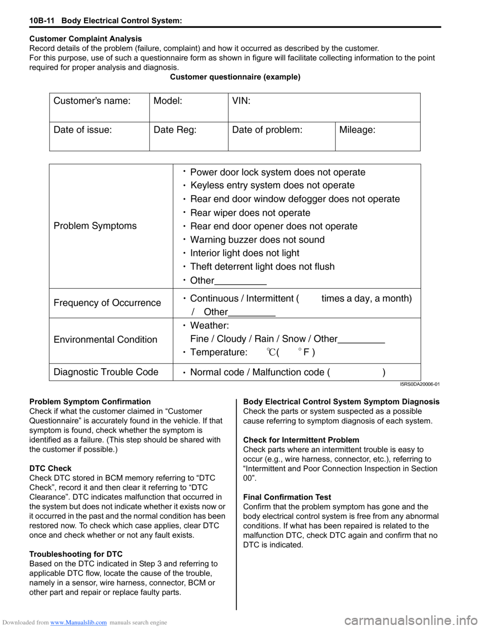
Customer Complaint Analysis
Record details of the problem (failure, complaint) and how it occurred as described by the customer.
For this purpose, use of such a questionnaire form as shown in figure will facilitate collectin g information to the point
required for proper analysis and diagnosis. Customer questionnaire (example)
Problem Symptom Confirmation
Check if what the custom er claimed in “Customer
Questionnaire” is accurately f ound in the vehicle. If that
symptom is found, check whether the symptom is
identified as a failure. (This step should be shared with
the customer if possible.)
DTC Check
Check DTC stored in BCM me mory referring to “DTC
Check”, record it and then clear it referring to “DTC
Clearance”. DTC indicates malfunction that occurred in
the system but does not indicate whether it exists now or
it occurred in the past and the normal condition has been
restored now. To check which case applies, clear DTC
once and check whether or not any fault exists.
Troubleshooting for DTC
Based on the DTC indicated in Step 3 and referring to
applicable DTC flow, locate the cause of the trouble,
namely in a sensor, wire harness, connector, BCM or
other part and repair or replace faulty parts. Body Electrical Control System Symptom Diagnosis
Check the parts or system
suspected as a possible
cause referring to symptom diagnosis of each system.
Check for Intermi ttent Problem
Check parts where an intermit tent trouble is easy to
occur (e.g., wire harness, connector, etc.), referring to
“Intermittent and Poor Connec tion Inspection in Section
00”.
Final Confirmation Test
Confirm that the problem symptom has gone and the
body electrical control system is free from any abnormal
conditions. If what has been repaired is related to the
malfunction DTC, check DTC again and confirm that no
DTC is indicated.
Customers name:
Model:
VIN:
Date of issue:
Date Reg:
Date of problem:
Mileage:
Problem Symptoms
Power door lock system does not operate
Keyless entry system does not operate
Rear end door window defogger does not operate
Rear wiper does not operate
Rear end door opener does not operate
Other
Frequency of Occurrence
Continuous / Intermittent ( times a day, a month)
/ Other
Environmental Condition
Weather:
Fine / Cloudy / Rain / Snow / Other
Temperature: (F )
Diagnostic Trouble Code Normal code / Malfunction code ( )
Warning buzzer does not sound
Interior light does not light
Theft deterrent light does not flush
I5RS0DA20006-01
Page 1420 of 1496
Downloaded from www.Manualslib.com manuals search engine 10B-17 Body Electrical Control System:
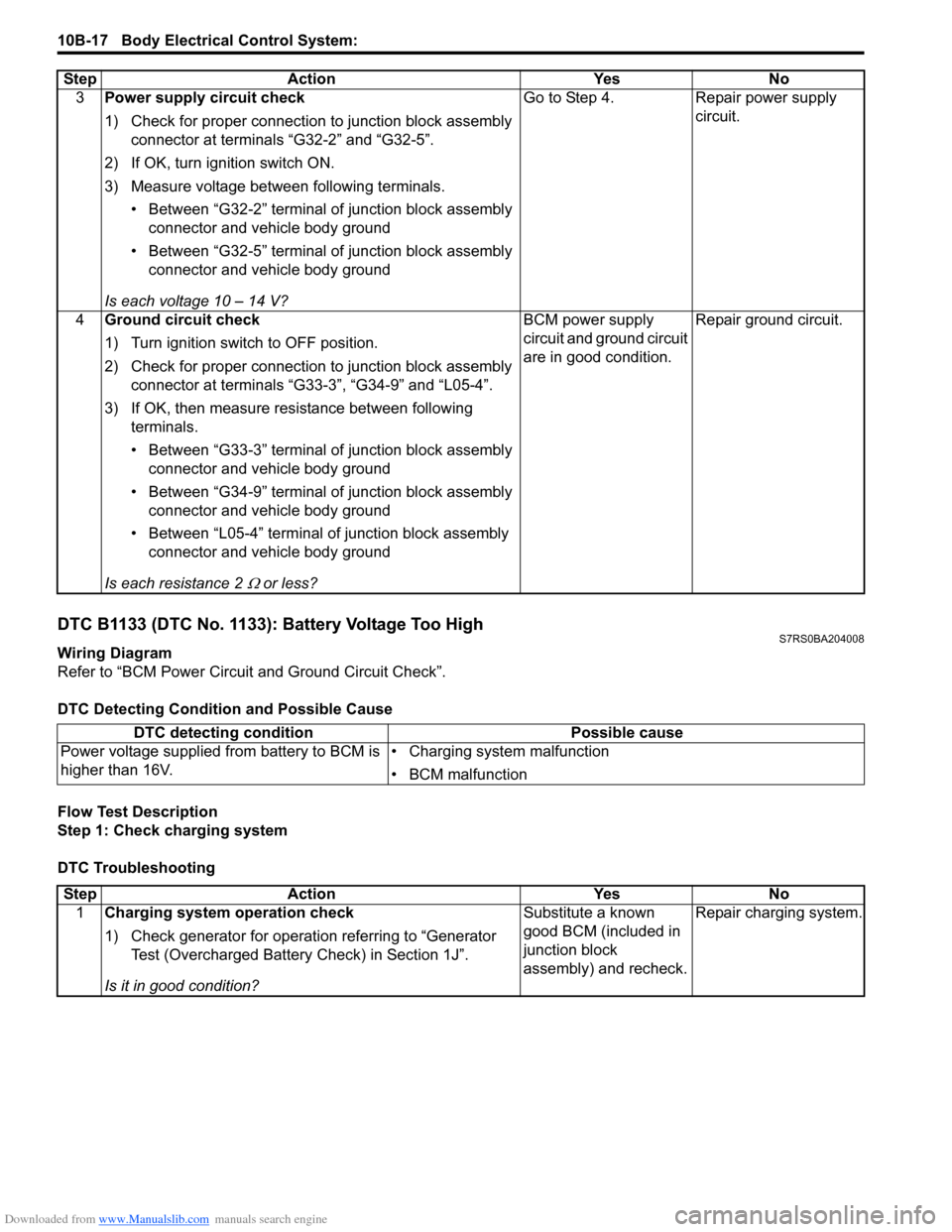
DTC B1133 (DTC No. 1133): Battery Voltage Too HighS7RS0BA204008
Wiring Diagram
Refer to “BCM Power Circuit and Ground Circuit Check”.
DTC Detecting Conditi on and Possible Cause
Flow Test Description
Step 1: Check charging system
DTC Troubleshooting 3
Power supply circuit check
1) Check for proper connection to junction block assembly
connector at terminals “G32-2” and “G32-5”.
2) If OK, turn ignition switch ON.
3) Measure voltage between following terminals. • Between “G32-2” terminal of junction block assembly connector and vehicle body ground
• Between “G32-5” terminal of junction block assembly connector and vehicle body ground
Is each voltage 10 – 14 V? Go to Step 4. Repair power supply
circuit.
4 Ground circuit check
1) Turn ignition switch to OFF position.
2) Check for proper connection to junction block assembly
connector at terminals “G33-3”, “G34-9” and “L05-4”.
3) If OK, then measure resistance between following terminals.
• Between “G33-3” terminal of junction block assembly connector and vehicle body ground
• Between “G34-9” terminal of junction block assembly connector and vehicle body ground
• Between “L05-4” terminal of junction block assembly connector and vehicle body ground
Is each resistance 2
Ω or less? BCM power supply
circuit and ground circuit
are in good condition.
Repair ground circuit.
Step Action Yes No
DTC detecting condition
Possible cause
Power voltage supplied from battery to BCM is
higher than 16V. • Charging system malfunction
• BCM malfunction
Step
Action YesNo
1 Charging system operation check
1) Check generator for operation referring to “Generator
Test (Overcharged Battery Check) in Section 1J”.
Is it in good condition? Substitute a known
good BCM (included in
junction block
assembly) and recheck.
Repair charging system.
Page 1421 of 1496
Downloaded from www.Manualslib.com manuals search engine Body Electrical Control System: 10B-18
DTC B1141 / DTC B1142 (No. 1141 / No. 1142): Outside Air Temperature (Ambient Temp.) Sensor
Circuit Malfunction
S7RS0BA204009
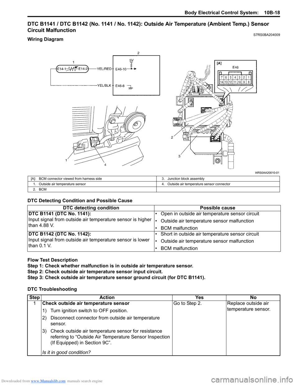
Wiring Diagram
DTC Detecting Condition and Possible Cause
Flow Test Description
Step 1: Check whether malfunction is in outside air temperature sensor.
Step 2: Check outside air temperature sensor input circuit.
Step 3: Check outside air temperature sensor ground circuit (for DTC B1141).
DTC Troubleshooting
I4RS0AA20010-01
[A]: BCM connector viewed from harness side 3. Junction block assembly
1. Outside air temperature sensor 4. Outside air temperature sensor connector
2. BCM
DTC detecting condition Possible cause
DTC B1141 (DTC No. 1141):
Input signal from outside air temperature sensor is higher
than 4.88 V. • Open in outside air temperature sensor circuit
• Outside air temperature sensor malfunction
• BCM malfunction
DTC B1142 (DTC No. 1142):
Input signal from outside air temperature sensor is lower
than 0.1 V. • Short in outside air temperature sensor circuit
• Outside air temperature sensor malfunction
• BCM malfunction
Step
Action YesNo
1 Check outside air temperature sensor
1) Turn ignition switch to OFF position.
2) Disconnect connector from outside air temperature
sensor.
3) Check outside air temperature sensor for resistance referring to “Outside Air Temperature Sensor Inspection
(If Equipped) in Section 9C”.
Is it in good condition? Go to Step 2.
Replace outside air
temperature sensor.
Page 1422 of 1496
Downloaded from www.Manualslib.com manuals search engine 10B-19 Body Electrical Control System:
DTC B1150 (No. 1150): Air Bag Communication Circuit MalfunctionS7RS0BA204010
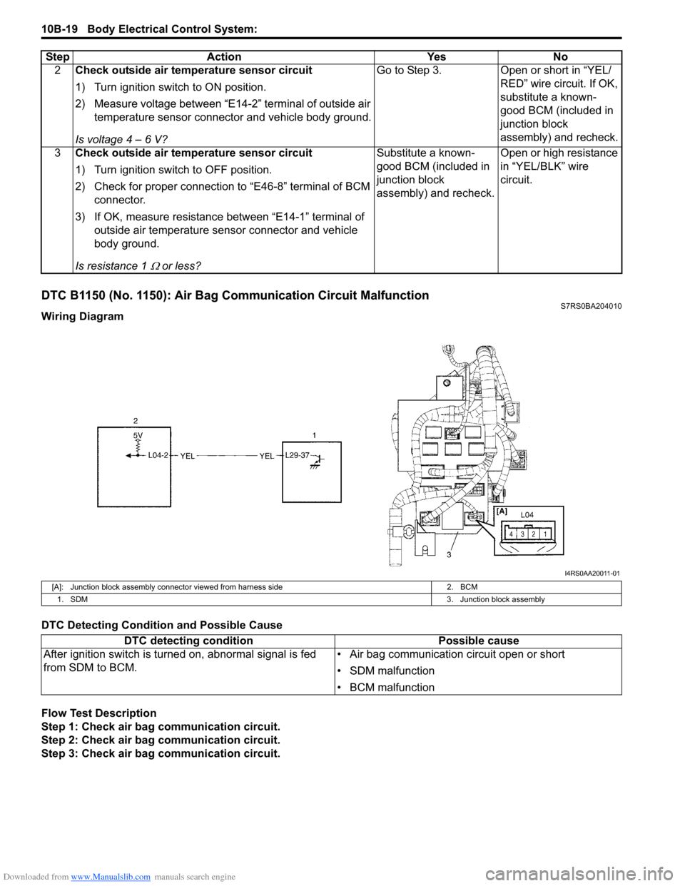
Wiring Diagram
DTC Detecting Condition and Possible Cause
Flow Test Description
Step 1: Check air bag communication circuit.
Step 2: Check air bag communication circuit.
Step 3: Check air bag communication circuit. 2
Check outside air temperature sensor circuit
1) Turn ignition switch to ON position.
2) Measure voltage between “E14-2” terminal of outside air
temperature sensor connector and vehicle body ground.
Is voltage 4 – 6 V? Go to Step 3. Open or short in “YEL/
RED” wire circuit. If OK,
substitute a known-
good BCM (included in
junction block
assembly) and recheck.
3 Check outside air temperature sensor circuit
1) Turn ignition switch to OFF position.
2) Check for proper connection to “E46-8” terminal of BCM
connector.
3) If OK, measure resistance between “E14-1” terminal of outside air temperature sens or connector and vehicle
body ground.
Is resistance 1
Ω or less? Substitute a known-
good BCM (included in
junction block
assembly) and recheck.
Open or high resistance
in “YEL/BLK” wire
circuit.
Step Action Yes No
I4RS0AA20011-01
[A]: Junction block assembly connect
or viewed from harness side 2. BCM
1. SDM 3. Junction block assembly
DTC detecting conditionPossible cause
After ignition switch is turned on, abnormal signal is fed
from SDM to BCM. • Air bag communication circuit open or short
• SDM malfunction
• BCM malfunction