2006 SUZUKI SWIFT Light control
[x] Cancel search: Light controlPage 1250 of 1496
Downloaded from www.Manualslib.com manuals search engine 9A-79 Wiring Systems:
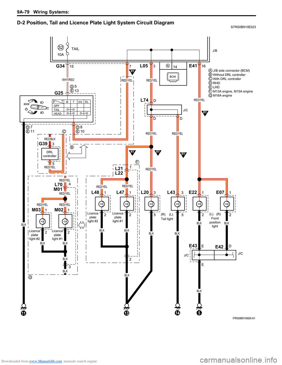
D-2 Position, Tail and Licence Plate Light System Circuit DiagramS7RS0B910E023
G
12M0212M03
BLKBLK
BLK
BLK
RED/YEL
RED/YEL
RED/YELRED/YEL
4
3L70
M01
3
5L431
2L47
(L) (R)
(R) (L)
BLK
RED/YELRED/YEL
RED/YEL
7
J/C
L74
E42
15G34
BLK
G25
10A TAIL
32
1
2E071
D
DD
2
ED EE22
BLK
BLK
RED/YEL
J/B
L053E4116
BLK
BLK
E43
J/C
Licence plate
light #1
3
5L20
BLK
BCM
14
11513
WHT/RED
OFF
TAIL
HEAD -BT
T
P(H) EL
A
Front
position light
RED/YEL
Tail light
RY
14
RY
RY
RY
J/C
J/B side connector (BCM)
Without DRL controller
With DRL controller
RHD
LHD
M13A engine, M15A engine
M16A engine
A
BCDEFG
L21
L22
RY
BLK
RED/YEL
RED/YEL
1
2L48
Licence plate
light #2
Licence plate
light #1
Licence
plate
light #2
RED/YEL
RED/BLK
RED/YEL
BLK
3
5G39
DRL
controller
1
2
DE5
13
DE7
11DE
B
F
C8
10
I7RS0B910926-01
Page 1252 of 1496
Downloaded from www.Manualslib.com manuals search engine 9A-81 Wiring Systems:
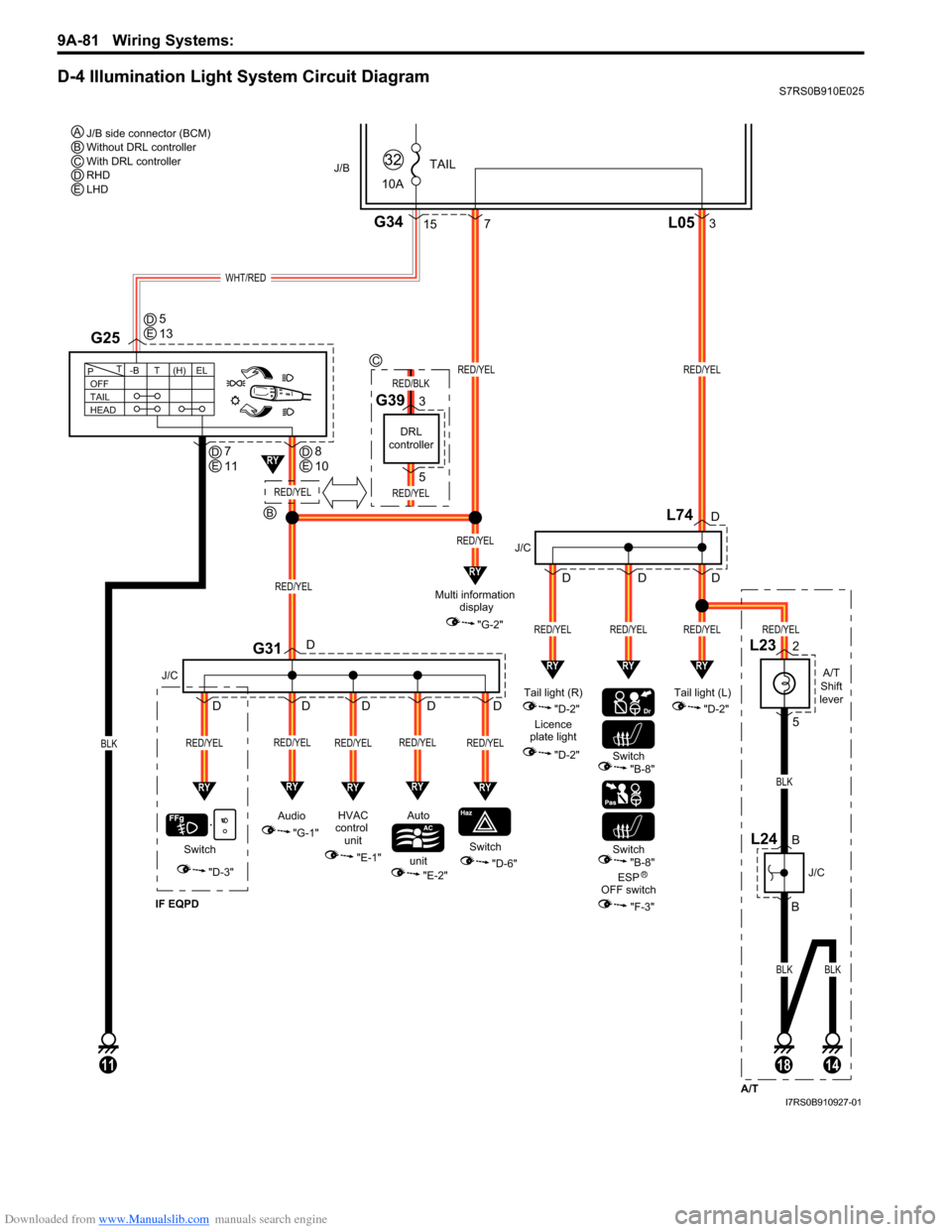
D-4 Illumination Light System Circuit DiagramS7RS0B910E025
WHT/RED
A/T
Shift
lever
L23
L742
5
BLK
BLKBLK
10A
TAIL
32J/B
15G34
BLK
G25
111814
A/T
B
B
J/C
L24
RED/YEL
RED/YEL
L053
"D-3"
IF EQPD
RY
Switch
J/C J/C
G31
RED/YEL
RY
RED/YEL
Switch
RY
RED/YEL
HVAC
control unit Auto
unit
"E-1"
"E-2""D-6"
OFF
TAIL
HEAD -BT
T
P(H) ELRED/YEL
7
RY
RED/YEL
Audio
"G-1"
D
D
D
D
D
D
D
RY
RED/YEL
D
D
RY
RY
RED/YEL
Multi information
display
"G-2"RED/YEL
RED/YEL
RED/YEL
RY
Tail light (L) "D-2"
RED/YEL
RY
Tail light (R) "D-2"
Licence
plate light
"D-2"
J/B side connector (BCM)
Without DRL controller
With DRL controller
RHD
LHD
A
R
BCDE
Switch
"B-8"
Switch"B-8"
ESP
OFF switch
"F-3"
DE5
13
DE7
11DE
B
C
8
10
DRL
controller
G393
5
RED/YEL
RED/BLK
RED/YEL
D
RY
I7RS0B910927-01
Page 1296 of 1496
Downloaded from www.Manualslib.com manuals search engine 9C-1 Instrumentation / Driver Info. / Horn:
Body, Cab and Accessories
Instrumentation / Driver Info. / Horn
Precautions
Precautions in Diagnosing Troubles for Combination MeterS7RS0B9300001
Combination meter uses signals (information) from each control module by CAN communication to control
speedometer, tachometer, engine coolant temp meter, warning light and indicator light (other than air bag warning
light, high beam indicator light, EPS warn ing light and turn signal indicator light). Therefore, check that no DTC is
detected in each module before performing combination me ter symptom diagnosis. If any DTC is detected, correct
trouble indicated by that DTC troubleshooting first.
General Description
CAN Communication System DescriptionS7RS0B9301001
Refer to “CAN Communication System Description in Section 1A” for Can communication system description.
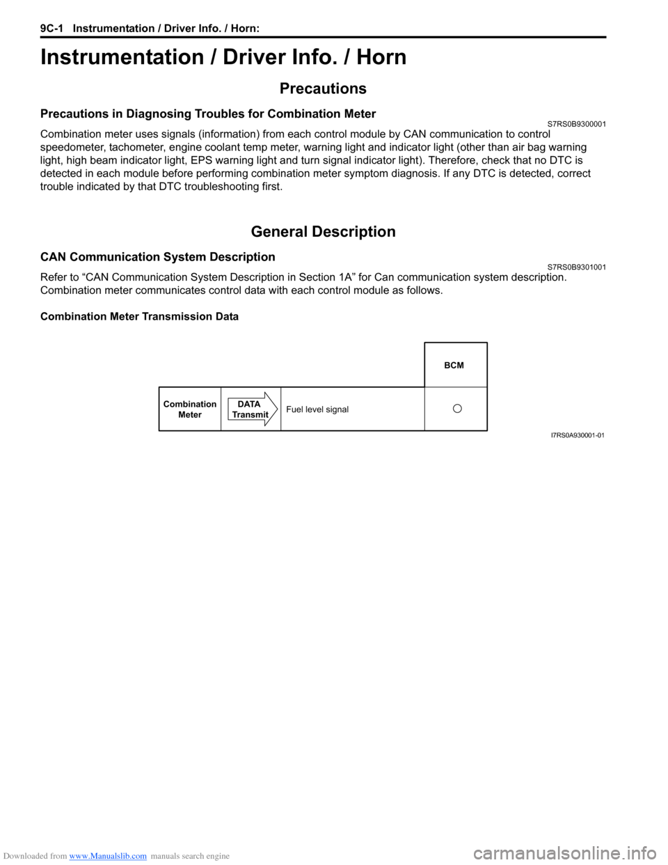
Combination meter communicates control data with each control module as follows.
Combination Meter Transmission Data
BCM
Combination Meter DATA
TransmitFuel level signal
I7RS0A930001-01
Page 1297 of 1496
Downloaded from www.Manualslib.com manuals search engine Instrumentation / Driver Info. / Horn: 9C-2
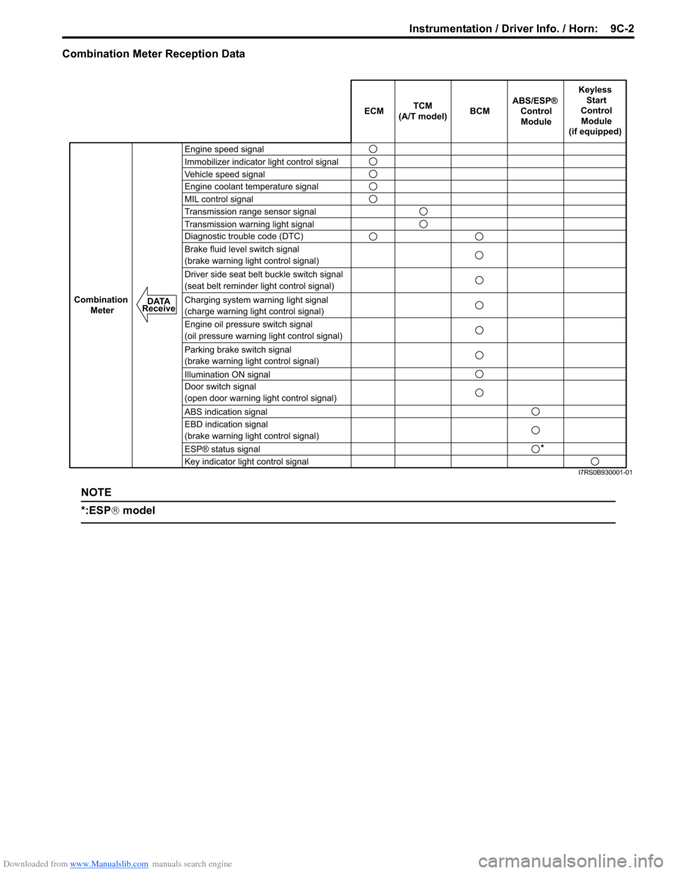
Combination Meter Reception Data
NOTE
*:ESP® model
ECM BCM
Keyless
Start
Control Module
(if equipped)
Combination Meter
TCM
(A/T model)
Engine speed signal
Immobilizer indicator light control signal
Vehicle speed signal
Engine coolant temperature signal
MIL control signal
Transmission range sensor signal
Transmission warning light signal
Diagnostic trouble code (DTC)
Brake fluid level switch signal
(brake warning light control signal)
Driver side seat belt buckle switch signal
(seat belt reminder light control signal)
Charging system warning light signal
(charge warning light control signal)
Engine oil pressure switch signal
(oil pressure warning light control signal)
Parking brake switch signal
(brake warning light control signal)
Illumination ON signal
Door switch signal
(open door warning light control signal)
ABS indication signal
EBD indication signal
(brake warning light control signal)
Key indicator light control signal ABS/ESP®
ControlModule
DATA
Receive
*
ESP® status signal
I7RS0B930001-01
Page 1300 of 1496
Downloaded from www.Manualslib.com manuals search engine 9C-5 Instrumentation / Driver Info. / Horn:
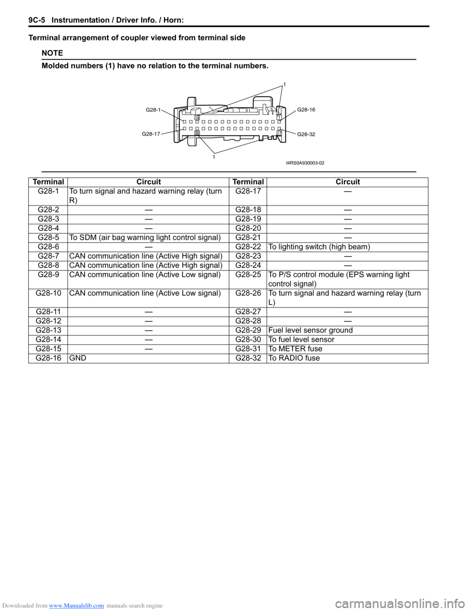
Terminal arrangement of coupler viewed from terminal side
NOTE
Molded numbers (1) have no relation to the terminal numbers.
TerminalCircuitTerminal Circuit
G28-1 To turn signal and hazard warning relay (turn R) G28-17
—
G28-2 —G28-18 —
G28-3 —G28-19 —
G28-4 —G28-20 —
G28-5 To SDM (air bag warning light control signal) G28-21 —
G28-6 —G28-22 To lighting switch (high beam)
G28-7 CAN communication line (Active High signal) G28-23 —
G28-8 CAN communication line (Active High signal) G28-24 —
G28-9 CAN communication line (Active Low signal) G 28-25 To P/S control module (EPS warning light
control signal)
G28-10 CAN communication line (Active Low signal) G28-26 To turn signal and hazard warning relay (turn L)
G28-11 —G28-27 —
G28-12 —G28-28 —
G28-13 —G28-29 Fuel level sensor ground
G28-14 —G28-30 To fuel level sensor
G28-15 —G28-31 To METER fuse
G28-16 GND G28-32 To RADIO fuse
G28-1 G28-16
G28-32
G28-17
1 1I4RS0A930003-02
Page 1351 of 1496
Downloaded from www.Manualslib.com manuals search engine Security and Locks: 9F-5
Keyless Entry System Operation InspectionS7RS0B9604004
NOTE
When performing the this inspection, make
sure to have any of the door once opened/
closed after the ignition key has been
removed from the ignition key cylinder.
1) Confirm that power door lock system operates normally, refer to “Power Door Lock System
Operation Inspection”.
2) All doors are closed and unlocked.
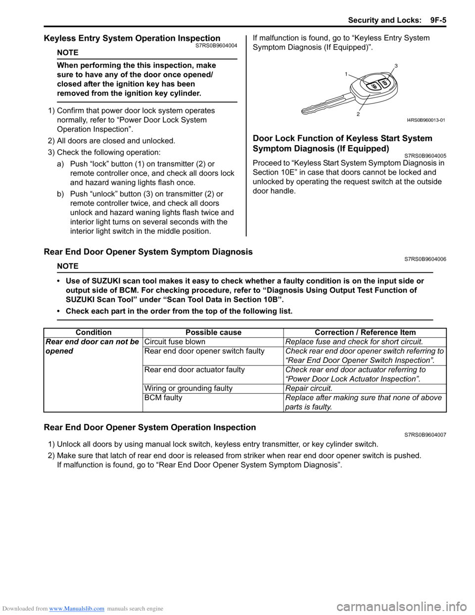
3) Check the following operation: a) Push “lock” button (1 ) on transmitter (2) or
remote controller once, and check all doors lock
and hazard waning lights flash once.
b) Push “unlock” button (3) on transmitter (2) or remote controller twice, and check all doors
unlock and hazard waning lights flash twice and
interior light turns on several seconds with the
interior light switch in the middle position. If malfunction is found, go to “Keyless Entry System
Symptom Diagnosis (If Equipped)”.
Door Lock Function of Keyless Start System
Symptom Diagnosis (If Equipped)
S7RS0B9604005
Proceed to “Keyless Start System Symptom Diagnosis in
Section 10E” in case that doors cannot be locked and
unlocked by operating the request switch at the outside
door handle.
Rear End Door Opener System Symptom DiagnosisS7RS0B9604006
NOTE
• Use of SUZUKI scan tool makes it easy to check wh
ether a faulty condition is on the input side or
output side of BCM. For checking procedure, re fer to “Diagnosis Using Output Test Function of
SUZUKI Scan Tool” under “Scan Tool Data in Section 10B”.
• Check each part in the order from the top of the following list.
Rear End Door Opener System Operation InspectionS7RS0B9604007
1) Unlock all doors by using manu al lock switch, keyless entry transmitter, or key cylinder switch.
2) Make sure that latch of rear end door is released from striker when rear end door opener switch is pushed. If malfunction is found, go to “Rear End Door Opener System Symptom Diagnosis”.
1
3
2I4RS0B960013-01
ConditionPossible cause Correction / Reference Item
Rear end door can not be
opened Circuit fuse blown
Replace fuse and check for short circuit.
Rear end door opener switch faulty Check rear end door opener switch referring to
“Rear End Door Opener Switch Inspection”.
Rear end door actuator faulty Check rear end door actuator referring to
“Power Door Lock Actuator Inspection”.
Wiring or grounding faulty Repair circuit.
BCM faulty Replace after making sure that none of above
parts is faulty.
Page 1401 of 1496
Downloaded from www.Manualslib.com manuals search engine Table of Contents 10- i
10
Section 10
CONTENTS
Control Systems
Precautions ............................................... 10-1
Precautions........................................................... 10-1
Precautions for Control Systems......................... 10-1
Body Electrical Contro l System ........... 10B-1
Precautions......................................................... 10B-1
Precautions in Diagnosing Trouble ................... 10B-1
General Description ........................................... 10B-1 BCM General Description ................................. 10B-1
CAN Communication System Description......... 10B-2
Theft Deterrent Light ......................................... 10B-3
Security Alarm Description (If Equipped) .......... 10B-3
Schematic and Routing Diagram ...................... 10B-4 Body Electrical Control System Wiring Circuit Diagram .......................................................... 10B-4
Connector Layout Diagram of BCM and Junction Block Assembly ................................ 10B-7
Component Locatio n ......................................... 10B-8
BCM and Related System Component Location .......................................................... 10B-8
Diagnostic Information an d Procedures .......... 10B-9
BCM Self-Diagnosis Function ........................... 10B-9
Body Electrical Control System Check............ 10B-10
Scan Tool Data ............................................... 10B-12
DTC Table ....................................................... 10B-14
DTC Check ..................................................... 10B-14
DTC Clearance ............................................... 10B-15
BCM Power Circuit and Ground Circuit Check 10B-16
DTC B1133 (DTC No. 1133): Battery Voltage Too High ....................................................... 10B-17
DTC B1141 / DTC B1142 (No. 1141 / No. 1142): Outside Air Temperature (Ambient
Temp.) Sensor Circuit Ma lfunction ................ 10B-18
DTC B1150 (No. 1150): Air Bag Communication Circuit Malfunction .............. 10B-19
DTC B1157 (No. 1157): Air Bag Deployment Signal Input ................................................... 10B-20
DTC B1170 (No. 1170 ): EEPROM Access
Error .............................................................. 10B-21
DTC U0155 (No. 0155): Lost Communication with Instrument Panel Cluster (IPC) Control
Module .......................................................... 10B-21
DTC U1073 (No. 1073): Control Module Communication Bus Off ................................ 10B-24 DTC U1100 (No. 1100): Lost Communication
with ECM ....................................................... 10B-25
DTC U1101 (No. 1101): Lost Communication with TCM ....................................................... 10B-27
DTC U1144 (No. 1144): Lost Communication with Keyless Start Control Module ................ 10B-29
Inspection of BCM and its Circuits .................. 10B-31
Repair Instructions ........... ...............................10B-39
BCM (Included in Junction Block Assembly) Removal and Installation ............................... 10B-39
Outside Air Temperature Sensor Removal and Installation .............................................. 10B-39
Outside Air Temperature Sensor Inspection ... 10B-39
Security Alarm Mode Selection Procedure (If Equipped) ...................................................... 10B-39
Special Tools and Equipmen t .........................10B-40
Special Tool .................................................... 10B-40
Immobilizer Control Syst em ................. 10C-1
Precautions.........................................................10C-1
Precautions in Diagnosing Troubles .................10C-1
Precaution in Replacing ECM ...........................10C-1
Precautions in Handli ng Immobilizer Control
System ............................................................10C-1
General Description ...........................................10C-2 Immobilizer Control System Introduction ..........10C-2
Immobilizer Control System Components Location...........................................................10C-3
On-Board Diagnostic System Description (Self-diagnosis Function) ................................10C-3
Schematic and Routing Diag ram ......................10C-4
Immobilizer Control System Wiring Circuit Diagram...........................................................10C-4
Diagnostic Information an d Procedures ..........10C-5
Immobilizer Control System Check ...................10C-5
Diagnostic Trouble Code (DTC) Check.............10C-5
Diagnostic Trouble Code (DTC) Clearance ......10C-6
Diagnostic Trouble Code (DTC) Table ..............10C-6
Scan Tool Data .................................................10C-7
Immobilizer Indicator Lamp Does Not Come ON with Ignition Switch ON and Engine Stop ..10C-7
Immobilizer Indicator Lamp Remains ON after Engine Starts...................................................10C-8
DTC P1614: Transponder Re sponse Error .......10C-9
Page 1402 of 1496
Downloaded from www.Manualslib.com manuals search engine 10-ii Table of Contents
DTC P1615: ID Code Does Not Registered (Vehicle equipped with keyless start system
only) ................................................................10C-9
DTC P1616: Different Registration ID Codes (Vehicle equipped with keyless start system
only) ..............................................................10C-10
DTC P1618: CAN Communication Error (Reception Error for Keyless Start Control
Module) (Vehicle equipped with keyless
start system only) ..........................................10C-11
DTC P1621: Immobilizer Communication Line Error ......................................................10C-12
DTC P1622: EEPROM Reading / Writing Error ..............................................................10C-13
DTC P1623: Unregistered Transponder .........10C-13
DTC P1625: Immobilizer An tenna Error..........10C-14
DTC P1636: Immobilizer Information Registration Failure .......................................10C-14
DTC P1638: Immobilizer Information Mismatched ...................................................10C-15
Inspection of Immobilizer Control Module (ICM) and Its Circuit ....... ...............................10C-16
Repair Instructions ........... ...............................10C-18
Immobilizer Control Mo dule (ICM) Removal
and Installation ..............................................10C-18
Registration of the Ignition Key .......................10C-18
Procedure after ECM Replacement ................10C-18
Special Tools and Equipmen t .........................10C-19
Special Tool ....................................................10C-19
Keyless Start System ....... ......................10E-1
General Description ........................................... 10E-1
Keyless Start System Description ..................... 10E-1
Parts and Functions .......................................... 10E-2
Keyless Engine Start Function .......................... 10E-3
Door Lock Function of Keyless Start System .... 10E-4
Operation Area of Remote Controller................ 10E-5
Alarm Function .................................................. 10E-6
CAN Communication System Description......... 10E-6
Schematic and Routing Diagram ...................... 10E-7 Keyless Start System El ectric Wiring Circuit
Diagram .......................................................... 10E-7
Diagnostic Information and Procedures .......... 10E-8 Precautions in Diagnosing Troubles ................. 10E-8
Self-Diagnosis Function .................................... 10E-8
Keyless Start System Diagn osis Introduction ... 10E-8 Keyless Start System Chec
k ............................. 10E-8
Customer Questionnaire (E xample) .................. 10E-9
Key Indicator Lamp Check .............................. 10E-10
DTC Check...................................................... 10E-10
DTC Table ....................................................... 10E-11
DTC Clearance ............................................... 10E-12
Keyless Start System Symp tom Diagnosis ..... 10E-12
Keyless Start System Operation Inspection .... 10E-13
Door Lock Operation (Keyless Start System) . 10E-14
Inspection of Keyless Start Control Module and Its Circuits .............................................. 10E-14
No DTC Detection After Performing DTC Check ............................................................ 10E-18
Key Indicator Lamp Circuit Check (Key indicator lamp doesn’t light when ignition
knob switch is pushed.) ................................. 10E-20
Keyless Start Control Module Power and Ground Circuit Check .................................... 10E-22
DTC No. 11: Communi cation Error with
Steering Lock Unit ......................................... 10E-23
DTC No. 13 / No. 14: Release Signal Error from Steering Lock Unit / Steering Lock Unit
Malfunction .................................................... 10E-24
DTC No. 21 / No. 22: Internal Error of Keyless Start Control Module (EEPROM reading
error) / (EEPROM writing error) ............ ........ 10E-24
DTC No. 31: Lost Commun ication with BCM .. 10E-25
DTC No. 33: Control Module Communication
Bus Off .......................................................... 10E-27
DTC No. 51 / No. 52 / No. 53: Driver Side / Passenger Side / Rear End Door Request
Switch Failure................................................ 10E-28
Repair Instructions ............ .............................. 10E-30
Antennas and Request Switches Removal and Installation .............................................. 10E-30
Front Door (Driver and Passenger Side), Rear End Door Request Switch Inspection............ 10E-31
Steering Lock Unit Removal and Installation .. 10E-31
Steering Lock Unit Inspection ......................... 10E-31
Front Door Lock Switch In spection ................. 10E-31
Keyless Start Control Module Removal and Installation ..................................................... 10E-32
Remote Controller Inspection.......................... 10E-32
Replacement of Remote Controller Battery .... 10E-32
Registration Procedure for Remote Controller
ID Code ......................................................... 10E-33