2006 SUZUKI SWIFT amount of engine coolant
[x] Cancel search: amount of engine coolantPage 35 of 1496

Downloaded from www.Manualslib.com manuals search engine Maintenance and Lubrication: 0B-5
4) Screw new filter on oil filter stand by hand until the filter O-ring contacts mounting surface.
CAUTION!
To tighten oil filter prop erly, it is important to
accurately identify the position at which filter
O-ring first contacts mounting surface.
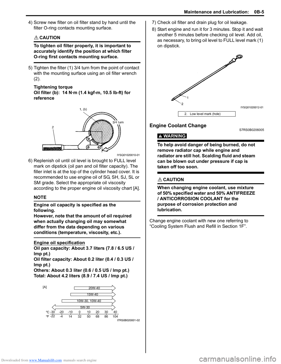
5) Tighten the filter (1) 3/4 tu rn from the point of contact
with the mounting surface using an oil filter wrench
(2).
Tightening torque
Oil filter (b): 14 N·m (1 .4 kgf-m, 10.5 lb-ft) for
reference
6) Replenish oil until oil leve l is brought to FULL level
mark on dipstick (oil pan and oil filter capacity). The
filler inlet is at the top of the cylinder head cover. It is
recommended to use engine oil of SG, SH, SJ, SL or
SM grade. Select the appropriate oil viscosity
according to the proper engine oil viscosity chart [A].
NOTE
Engine oil capacity is specified as the
following.
However, note that the amount of oil required
when actually changing oil may somewhat
differ from the data depending on various
conditions (temperature, viscosity, etc.).
Engine oil specification
Oil pan capacity: About 3.7 liters (7.8 / 6.5 US /
lmp pt.)
Oil filter capacity: About 0.2 liter (0.4 / 0.3 US /
lmp pt.)
Others: About 0.3 liter (0 .6 / 0.5 US / lmp pt.)
Total: About 4.2 liters (8.9 / 7.4 US / lmp pt.) 7) Check oil filter and drain plug for oil leakage.
8) Start engine and run it for 3 minutes. Stop it and wait
another 5 minutes before checking oil level. Add oil,
as necessary, to bring oil le vel to FULL level mark (1)
on dipstick.
Engine Coolant ChangeS7RS0B0206005
WARNING!
To help avoid danger of being burned, do not
remove radiator cap while engine and
radiator are still hot. Scalding fluid and steam
can be blown out under pressure if cap is
taken off too soon.
CAUTION!
When changing engine coolant, use mixture
of 50% specified water and 50% ANTIFREEZE
/ ANTICORROSION COOLANT for the
purpose of corrosion protection and
lubrication.
Change engine coolant with new one referring to
“Cooling System Flush and Refill in Section 1F”.
IYSQ01020010-01
Co
Fo-30
-22 -20
-4 -10
14 32 50 68 86 104 010203040
5W-30
20W-40
15W-40
10W-30, 10W-40
[A]
I7RS0B020001-02
2. Low level mark (hole)
IYSQ01020012-01
Page 972 of 1496

Downloaded from www.Manualslib.com manuals search engine 7B-24 Air Conditioning System: Manual Type
HVAC Unit Removal and InstallationS7RS0B7216006
Removal1) Disconnect negative (–) cable from battery.
2) Disable air bag system referring to “Disabling Air Bag System in Section 8B”.
3) Recover refrigerant from A/C system with recovery and recycling equipment referring to “Recovery” in
“Operation Procedure for Refrigerant Charge”.
4) Remove cowl top panel referring to “Cowl Top Components in Section 9K”.
5) Drain engine coolant, and then disconnect heater hoses (1) from HVAC unit (2).
6) Remove instrument panel from vehicle body referring to “Audio Unit Re moval and Installation in
Section 9C”.
7) Loosen suction hose and liquid pipe bolt (4).
8) Remove nuts (3).
9) Remove HVAC unit from vehicle body. Installation
Reverse removal procedure noting the following
instructions.
• Replenish specified amount of compressor oil to
compressor suction side referring to “Replenishing
Compressor Oil” in “Operation Procedure for
Refrigerant Charge”.
• Install the padding (1) to the installation hole uniformly.
• Evacuate and charge the A/C system referring to “Evacuation” and “Charge” in “Operation Procedure
for Refrigerant Charge”.
• Adjust control cables referr ing to “HVAC Control Unit
Removal and Installati on in Section 7A”.
• Enable air bag system referring to “Enabling Air Bag System in Section 8B”.
Evaporator InspectionS7RS0B7216007
Check the followings.
• Clog of A/C evaporator fins.If any clogs are found, A/C evaporator fins should be
washed with water, and then should be dried with
compressed air.
• A/C evaporator fins for leakage and breakage. If any defects are found, repair or replace A/C
evaporator.
• A/C evaporator fittings for leakage. If any defects are found, repair or replace A/C
evaporator.
2. Blower upper case 8. Temperature control door assembly 14. Temperature control lever 20. Packing
3. Air intake control actuator 9. Blower motor resistor 15. Airflow control lever21. Filter cover (if equipped)
4. HVAC Air filter (if equipped) 10. Blower lower case 16. Evaporator22. Drain hose
5. Heater unit upper case 11. Blower motor 17. O-ring23. Cable lock clamp
6. Foot duct 12. Heater unit lower case 18. Expansion valve: Do not reuse.
3
2
3
3
1
4
I4RS0B720009-01
1
I4RS0B720010-01
Page 982 of 1496

Downloaded from www.Manualslib.com manuals search engine 7B-34 Air Conditioning System: Automatic Type
Automatic Type
Precautions
A/C System CautionS7RS0B7220001
Refer to “A/C System Caution”.
Precautions in Diagnosing TroubleS7RS0B7220002
• Do not disconnect couplers from HVAC control module, battery cable from battery, HVAC control module ground
wire harness from body or main fuse before confirming diagnostic information (diagnostic trouble code) stored in
HVAC control module memory.
• Diagnostic information (diagnostic trouble code) stored in HVAC control module can be checked by display of HVAC
control module. Also, it can be checked by using SU ZUKI scan tool. Before checking diagnostic information
(diagnostic trouble code), read this manual and operator's manual for SUZUKI scan tool to know how to read
diagnostic information (diagnostic trouble code).
• When trouble is diagnosed using diagnostic information (diagnostic trouble code) on display of HVAC control
module, keep in your mind that each diagnostic inform ation (diagnostic trouble code) has priority, and only
diagnostic information (diagnostic troub le code) which has the highest priority is indicated. Therefore, after
troubleshooting the malfunction, make sure if there exists any other diagnostic information (diagnostic trouble
code).
• Be sure to read “Precautions for Electrical Circuit Service in Section 00” before inspection.
Precautions on Servicing A/C SystemS7RS0B7220003
Refer to “Precautions on Servicing A/C System”.
General Description
Auto A/C System DescriptionS7RS0B7221001
The automatic type air conditioning system (auto A/C) is pr ovided with the function to automatically control the inside
air temperature, fan speed, air flow outl et direction and air intake position by HVAC control module in addition to
functions of the manual type air conditioning system (manua l A/C). Once the inside air temperature is set using the
temperature selector, HVAC control module automatically controls the inside air temperature at the constant level at all
times based on the inside air temperature, outside ai r temperature, amount of sunlight and engine coolant
temperature detected respectively by the inside air te mperature sensor, outside air temperature sensor, sunload
sensor and ECT sensor. At this time, “FULL AUTO A/ C” appears on the display of HVAC control module.
With the air intake selector pushed in the above state, it is possible to select any position of the air intake actuator.
Then, “FULL AUTO A/C” on the display changes to “AUTO A/C”.
Page 993 of 1496

Downloaded from www.Manualslib.com manuals search engine Air Conditioning System: Automatic Type 7B-45
NOTE
When no current DTC is detected, all contents displayed on display (1) of HVAC control module and
defroster indicator (2) flash at the same time.
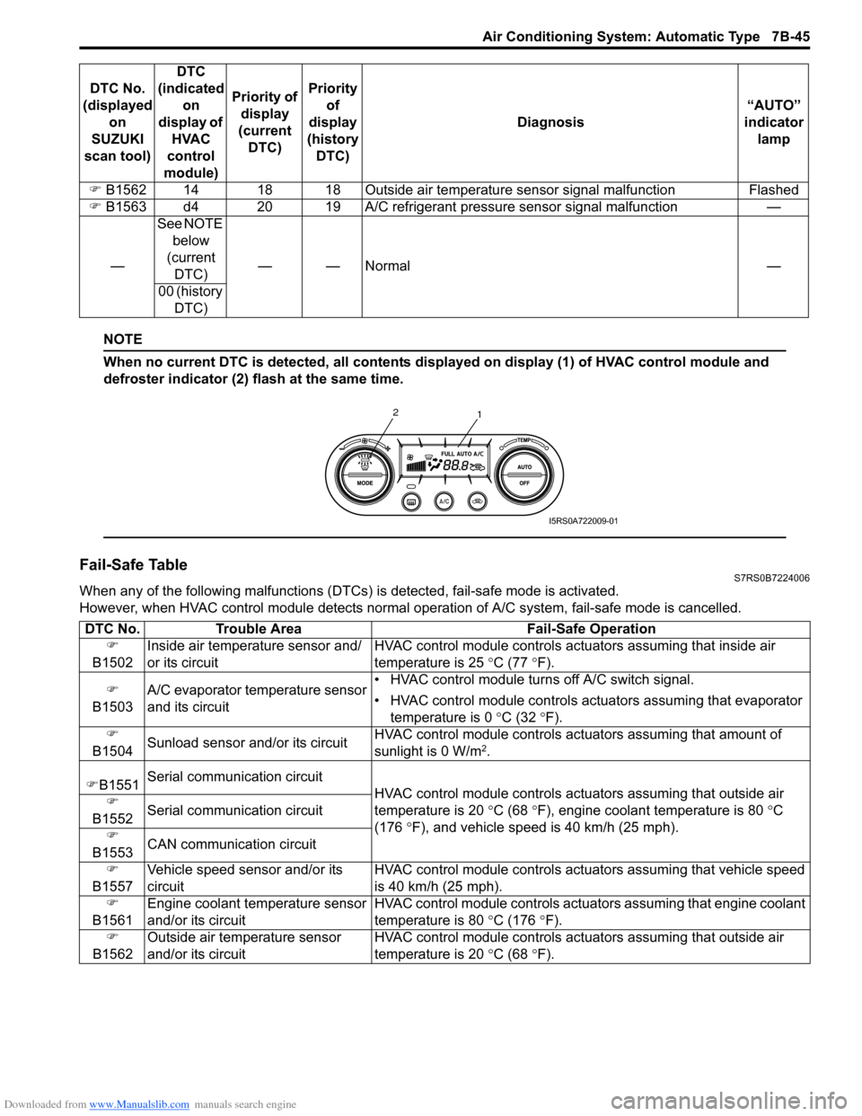
Fail-Safe TableS7RS0B7224006
When any of the following malfunctions (DTCs) is detected, fail-safe mode is activated.
However, when HVAC control module detects normal ope ration of A/C system, fail-safe mode is cancelled.
�)
B1562 14 18 18 Outside air temperatur e sensor signal malfunction Flashed
�) B1563 d4 20 19 A/C refrigerant pressure sensor signal malfunction —
— See NOTE
below
(current DTC) ——Normal —
00 (history DTC)
DTC No.
(displayed on
SUZUKI
scan tool) DTC
(indicated on
display of HVAC
control
module) Priority of
display
(current DTC) Priority
of
display
(history DTC) Diagnosis
“AUTO”
indicator lamp
1
2
I5RS0A722009-01
DTC No.
Trouble Area Fail-Safe Operation
�)
B1502 Inside air temperature sensor and/
or its circuit HVAC control module controls actu
ators assuming that inside air
temperature is 25 ° C (77 °F).
�)
B1503 A/C evaporator temperature sensor
and its circuit • HVAC control module turn
s off A/C switch signal.
• HVAC control module controls actu ators assuming that evaporator
temperature is 0 ° C (32 °F).
�)
B1504 Sunload sensor and/or its circuit HVAC control module controls actu
ators assuming that amount of
sunlight is 0 W/m
2.
�) B1551 Serial communication circuit
HVAC control module controls actuators assuming that outside air
temperature is 20 ° C (68 °F), engine coolant temperature is 80 °C
(176 °F), and vehicle speed is 40 km/h (25 mph).
�)
B1552 Serial communication circuit
�)
B1553 CAN communication circuit
�)
B1557 Vehicle speed sensor and/or its
circuit HVAC control module controls act
uators assuming that vehicle speed
is 40 km/h (25 mph).
�)
B1561 Engine coolant temperature sensor
and/or its circuit HVAC control module controls act
uators assuming that engine coolant
temperature is 80 ° C (176 °F).
�)
B1562 Outside air temperature sensor
and/or its circuit HVAC control module controls actu
ators assuming that outside air
temperature is 20 ° C (68 °F).
Page 995 of 1496

Downloaded from www.Manualslib.com manuals search engine Air Conditioning System: Automatic Type 7B-47
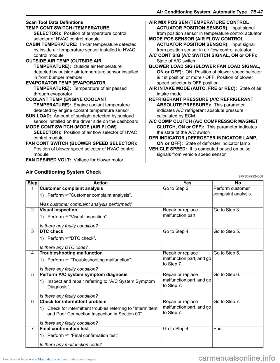
Scan Tool Data Definitions
TEMP CONT SWITCH (TEMPERATURE SELECTOR): Position of temperature control
selector of HVAC control module
CABIN TEMPERATURE: In-car temperature detected
by inside air temperature sensor installed in HVAC
control module
OUTSIDE AIR TEMP (OUTSIDE AIR TEMPERATURE): Outside air temperature
detected by outside air temperature sensor installed
in front bumper member
EVAPORATOR TEMP (EVAPORATOR TEMPERATURE): Temperature of air passed
through evaporator
COOLANT TEMP (ENGINE COOLANT TEMPERATURE): Engine coolant temperature
detected by engine coolant temperature sensor
SUN LOAD: Amount of sunlight detected by sunload
sensor installed on the driver side on the dashboard
MODE CONT SWITCH (MODE (AIR FLOW) SELECTOR): Position of air flow selector of HVAC
control module
FAN CONT SWITCH (BLOWER SPEED SELECTOR): Position of blower speed selector of HVAC control
module
FAN DESIRED VOLT: Voltage for blower motor AIR MIX POS SEN (TEMPERATURE CONTROL
ACTUATOR POSITI ON SENSOR): Input signal
from position sensor in temperature control actuator
MODE POS SENSOR (AIR FLOW CONTROL ACTUATOR POSITI ON SENSOR): Input signal
from position sensor in air flow control actuator
A/C CONT SIG (A/C SWITCH SIGNAL, ON or OFF): State of A/C switch
BLOWER LOAD SIG (BLO WER FAN LOAD SIGNAL,
ON or OFF): ON: Position of blower speed selector
is 1st position or more / OFF: Position of blower
speed selector is OFF position.
AIR INTAKE MODE (AUTO, FRE or REC): State of air
intake mode
REFRIGERANT PRESSURE (A/C REFRIGERANT ABSOLUTE PRESSURE): This parameter
indicates A/C refrigerant absolute pressure
calculated by ECM
A/C COMP CLUTCH (A/C COMPRESSOR MAGNET CLUTCH, ON or OFF): This parameter indicates
the state of the A/C switch
DFR INDICATOR (DEFROSTER INDICATOR LAMP, ON or OFF): State of defroster indicator lamp
VEHICLE SPEED: It is computed based on pulse
signals from vehicle speed sensor
Air Conditioning System CheckS7RS0B7224008
Step Action YesNo
1 Customer complaint analysis
1) Perform �)”Customer complaint analysis”.
Was customer complaint analysis performed? Go to Step 2.
Perform customer
complaint analysis.
2 Visual inspection
1) Perform �)“Visual inspection”.
Is there any faulty condition? Repair or replace
malfunction part.
Go to Step 3.
3 DTC check
1) Perform �)“DTC check”.
Is there any DTC code? Go to Step 4.
Go to Step 5.
4 Troubleshooting malfunction
1) Perform �) “Troubleshooting malfunction”.
Is there any faulty condition? Repair or replace
malfunction part, and go
to Step 7.
Go to Step 5.
5 Perform A/C system symptom diagnosis
1) Inspect and repair referri ng to “A/C System Symptom
Diagnosis”.
Is there any faulty condition? Repair or replace
malfunction part, and go
to Step 7.
Go to Step 6.
6 Check for intermittent problem
1) Check for intermittent troubles referring to “Intermittent
and Poor Connection Inspection in Section 00”.
Is there any faulty condition? Repair or replace
malfunction part, and go
to Step 7.
Go to Step 7.
7 Final confirmation test
1) Perform �) “Final confirmation test”.
Is there any malfunction code? Go to Step 4.
End.
Page 1302 of 1496

Downloaded from www.Manualslib.com manuals search engine 9C-7 Instrumentation / Driver Info. / Horn:
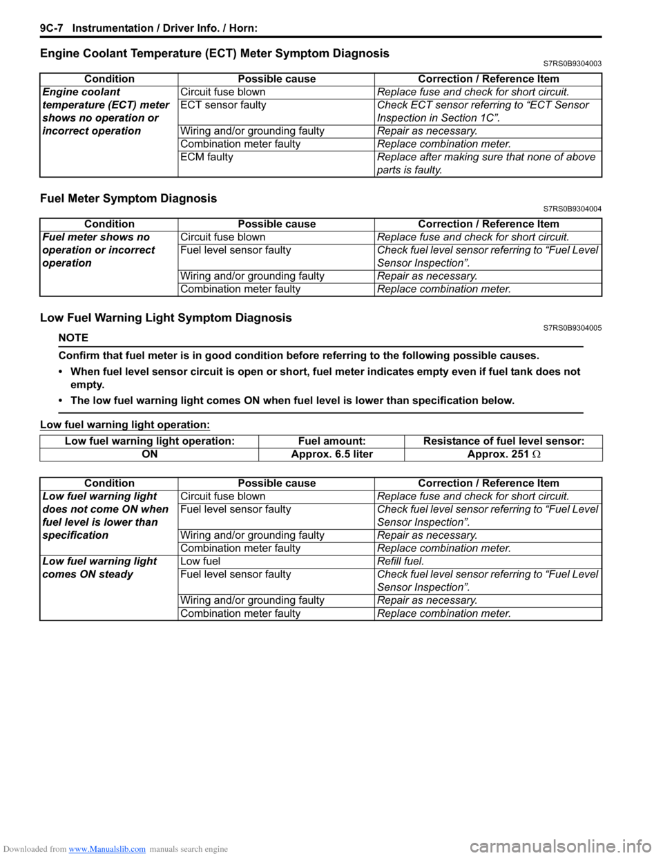
Engine Coolant Temperature (ECT) Meter Symptom DiagnosisS7RS0B9304003
Fuel Meter Symptom DiagnosisS7RS0B9304004
Low Fuel Warning Light Symptom DiagnosisS7RS0B9304005
NOTE
Confirm that fuel meter is in good condition before referring to the following possible causes.
• When fuel level sensor circuit is open or short, fuel meter indicates empty even if fuel tank does not empty.
• The low fuel warning light comes ON when fu el level is lower than specification below.
Low fuel warning light operation:
ConditionPossible cause Correction / Reference Item
Engine coolant
temperature (ECT) meter
shows no operation or
incorrect operation Circuit fuse blown
Replace fuse and check for short circuit.
ECT sensor faulty Check ECT sensor referring to “ECT Sensor
Inspection in Section 1C”.
Wiring and/or grounding faulty Repair as necessary.
Combination meter faulty Replace combination meter.
ECM faulty Replace after making sure that none of above
parts is faulty.
ConditionPossible cause Correction / Reference Item
Fuel meter shows no
operation or incorrect
operation Circuit fuse blown
Replace fuse and check for short circuit.
Fuel level sensor faulty Check fuel level sensor referring to “Fuel Level
Sensor Inspection”.
Wiring and/or grounding faulty Repair as necessary.
Combination meter faulty Replace combination meter.
Low fuel warning light operation: Fuel amount: Resistance of fuel level sensor:
ON Approx. 6.5 liter Approx. 251 Ω
Condition Possible cause Correction / Reference Item
Low fuel warning light
does not come ON when
fuel level is lower than
specification Circuit fuse blown
Replace fuse and check for short circuit.
Fuel level sensor faulty Check fuel level sensor referring to “Fuel Level
Sensor Inspection”.
Wiring and/or grounding faulty Repair as necessary.
Combination meter faulty Replace combination meter.
Low fuel warning light
comes ON steady Low fuel
Refill fuel.
Fuel level sensor faulty Check fuel level sensor referring to “Fuel Level
Sensor Inspection”.
Wiring and/or grounding faulty Repair as necessary.
Combination meter faulty Replace combination meter.