2006 SUZUKI SWIFT cent
[x] Cancel search: centPage 1159 of 1496
Downloaded from www.Manualslib.com manuals search engine Air Bag System: 8B-121
Deployment / Activation Inside of Vehicle
When the vehicle will be destroyed, or salvaged for
component parts, deploy the air bag modules and/or
activate seat belt pretensioners installed on vehicle.
NOTE
If equipped with the seat belt pretensioners,
activate both side of seat belt pretensioners
at the same time when using special tool (C).
1) Turn ignition switch to LOCK position, remove key
and put on safety glasses.
2) Remove all loose objects from front seats and instrument panel.
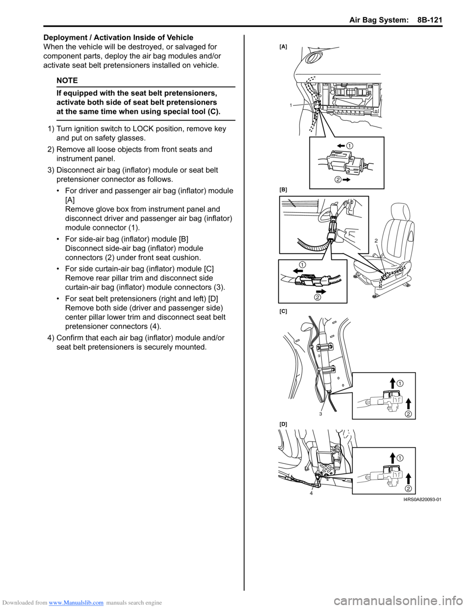
3) Disconnect air bag (inflator) module or seat belt pretensioner connector as follows.
• For driver and passenger air bag (inflator) module [A]
Remove glove box from instrument panel and
disconnect driver and passenger air bag (inflator)
module connector (1).
• For side-air bag (inflator) module [B] Disconnect side-air bag (inflator) module
connectors (2) under front seat cushion.
• For side curtain-air bag (inflator) module [C] Remove rear pillar trim and disconnect side
curtain-air bag (inflator) module connectors (3).
• For seat belt pretensioners (right and left) [D] Remove both side (driver and passenger side)
center pillar lower trim an d disconnect seat belt
pretensioner connectors (4).
4) Confirm that each air bag (inflator) module and/or seat belt pretensioners is securely mounted.
[A]
[B]
[C]
[D]
2
1
3
4
1
2
1
2
1
2
1
2
I4RS0A820093-01
Page 1209 of 1496
Downloaded from www.Manualslib.com manuals search engine Wiring Systems: 9A-38
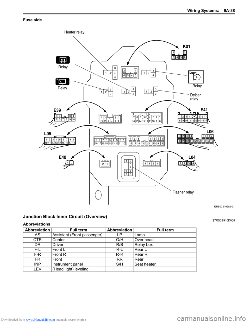
Fuse side
Junction Block Inner Circuit (Overview)S7RS0B910D008
Abbreviations
123
4 5
1 2 3
4 1
2 3
4 1
2 3
4
1 23
4
Heater relay
Relay
Deicer
relay
23412112
12 34 5 6 78 9 15 16 17 18
1110 12 13 14 4
3 561214
11
10 15
721
13
16
98
1
234
5 678 910
4321
10 987 656
5
4
3
2
17
11
10
9
8
15
14
13
12 16
987654321
13 12 11 10
1718 16 15 14
13
14
15
16
9
10
11
12 8
5
6
7 2
3
4 1
321
4
E39
L05
E40 L04L06
E41
H
Relay
Relay
12 34
6
5
8
7
4 3
5
6
1214 11 10
15
7
2
1
13
16 9 8
3456
12
K01
6543
21
Flasher relay
I5RS0C910902-01
Abbreviation Full term Abbreviation Full term
AS Assistant (Front passenger) LP Lamp
CTR Center O/H Over head
DR Driver R/B Relay box
F-L Front L R-L Rear L
F-R Front R R-R Rear R
FR Front RR Rear
INP Instrument panel S/H Seat heater
LEV (Head light) leveling
Page 1289 of 1496
Downloaded from www.Manualslib.com manuals search engine Lighting Systems: 9B-7
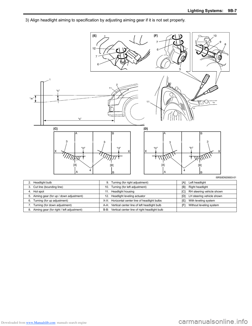
3) Align headlight aiming to specification by adjusting aiming gear if it is not set properly.
I5RS0D920003-01
2. Headlight bulb 9. Turning (for right adjustment)[A]: Left headlight
3. Cut line (bounding line) 10. Turning (for left adjustment) [B]: Right headlight
4. Hot spot 11. Headlight housing [C]: RH steering vehicle shown
5. Aiming gear (for up / down adjustment) 12. Headlight leveling actuator [D]: LH steering vehicle shown
6. Turning (for up adjustment) X-X: Horizontal center line of headlight bulbs [E]: With leveling system
7. Turning (for down adjustment) A-A: Vertical center line of left headlight bulb [F]: Without leveling system
8. Aiming gear (for right / left adjustment) B-B: Vertical center line of right headlight bulb
Page 1290 of 1496
Downloaded from www.Manualslib.com manuals search engine 9B-8 Lighting Systems:
Headlight Switch (in Lighting Switch) Removal
and Installation
S7RS0B9206004
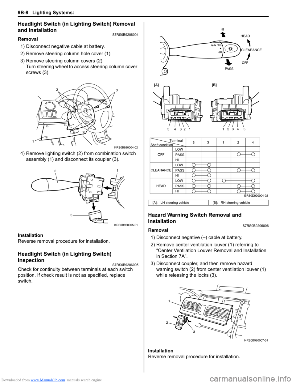
Removal1) Disconnect negative cable at battery.
2) Remove steering column hole cover (1).
3) Remove steering column covers (2). Turn steering wheel to acce ss steering column cover
screws (3).
4) Remove lighting switch (2 ) from combination switch
assembly (1) and disconnect its coupler (3).
Installation
Reverse removal procedure for installation.
Headlight Switch (in Lighting Switch)
Inspection
S7RS0B9206005
Check for continuity between terminals at each switch
position. If check result is not as specified, replace
switch.
Hazard Warning Switch Removal and
Installation
S7RS0B9206006
Removal 1) Disconnect negative (–) cable at battery.
2) Remove center ventilation louver (1) referring to
“Center Ventilation Louver Removal and Installation
in Section 7A”.
3) Disconnect coupler, and then remove hazard warning switch (2) from center ventilation louver (1)
while releasing the locks (3).
Installation
Reverse removal procedure for installation.
1
32
I4RS0B920004-02
1
2
3
I4RS0B920005-01
[A]: LH steering vehicle [B]: RH steering vehicle
Terminal
Shaft condition
OFF 5
3124
LOW
PASS
HI
LOW
PASS
HI LOW
PASS
HI
CLEARANCE
HEAD
HEADCLEARANCE
OFF
HI
PA S S
54321
54321
[A][B]
I5RS0D920004-02
1
2 3
I4RS0B920007-01
Page 1294 of 1496
Downloaded from www.Manualslib.com manuals search engine 9B-12 Lighting Systems:
Front Fog Light Aiming Adjustment with Screen
(If Equipped)
S7RS0B9206018
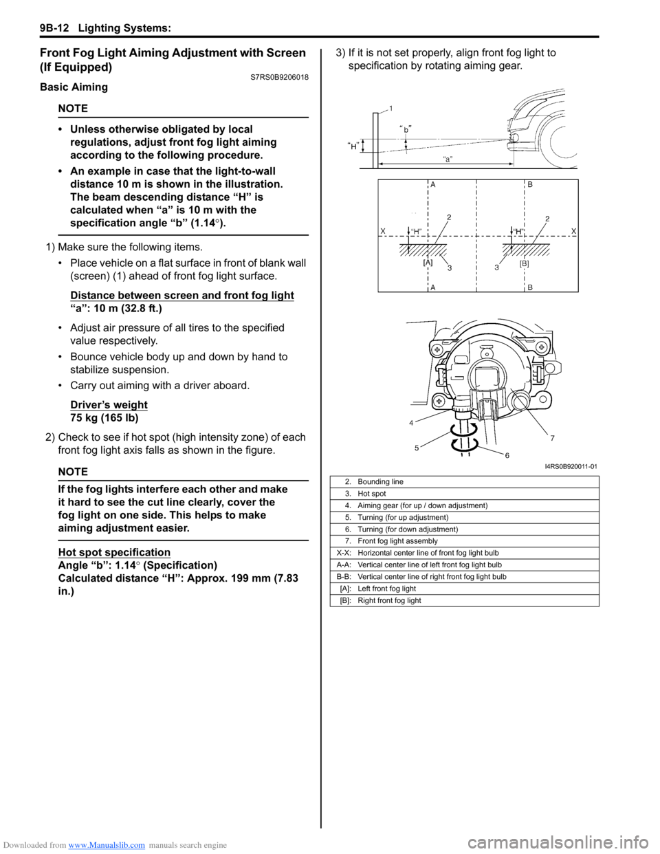
Basic Aiming
NOTE
• Unless otherwise obligated by local regulations, adjust front fog light aiming
according to the following procedure.
• An example in case that the light-to-wall distance 10 m is shown in the illustration.
The beam descending distance “H” is
calculated when “a” is 10 m with the
specification angle “b” (1.14 °).
1) Make sure the following items.
• Place vehicle on a flat surface in front of blank wall (screen) (1) ahead of front fog light surface.
Distance between screen and front fog light
“a”: 10 m (32.8 ft.)
• Adjust air pressure of all tires to the specified value respectively.
• Bounce vehicle body up and down by hand to stabilize suspension.
• Carry out aiming with a driver aboard.
Driver’s weight
75 kg (165 lb)
2) Check to see if hot spot (h igh intensity zone) of each
front fog light axis falls as shown in the figure.
NOTE
If the fog lights interfere each other and make
it hard to see the cut line clearly, cover the
fog light on one side. This helps to make
aiming adjustment easier.
Hot spot specification
Angle “b”: 1.14° (Specification)
Calculated distance “H”: Approx. 199 mm (7.83
in.) 3) If it is not set properly
, align front fog light to
specification by rotating aiming gear.
2. Bounding line
3. Hot spot
4. Aiming gear (for up / down adjustment)
5. Turning (for up adjustment)
6. Turning (for down adjustment)
7. Front fog light assembly
X-X: Horizontal center line of front fog light bulb
A-A: Vertical center line of left front fog light bulb
B-B: Vertical center line of right front fog light bulb [A]: Left front fog light
[B]: Right front fog light
I4RS0B920011-01
Page 1313 of 1496
Downloaded from www.Manualslib.com manuals search engine Instrumentation / Driver Info. / Horn: 9C-18
Instrument Panel Removal and InstallationS7RS0B9306015
WARNING!
Refer to “Air Bag Warning in Section 00”
before starting service work.
Removal
1) Disconnect negative (–) cable at battery.
2) Disable air bag system referring to “Disabling Air Bag System in Section 8B”.
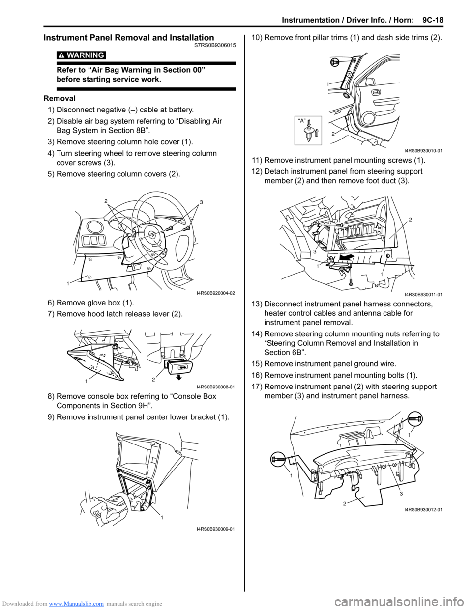
3) Remove steering column hole cover (1).
4) Turn steering wheel to remove steering column cover screws (3).
5) Remove steering column covers (2).
6) Remove glove box (1).
7) Remove hood latch release lever (2).
8) Remove console box referring to “Console Box Components in Section 9H”.
9) Remove instrument panel center lower bracket (1). 10) Remove front pillar trims
(1) and dash side trims (2).
11) Remove instrument panel mounting screws (1).
12) Detach instrument panel from steering support member (2) and then remove foot duct (3).
13) Disconnect instrument panel harness connectors, heater control cables and antenna cable for
instrument panel removal.
14) Remove steering column mounting nuts referring to “Steering Column Remova l and Installation in
Section 6B”.
15) Remove instrument panel ground wire.
16) Remove instrument panel mounting bolts (1).
17) Remove instrument panel (2) with steering support member (3) and instrument panel harness.
1
32
I4RS0B920004-02
2
1I4RS0B930008-01
1
I4RS0B930009-01
“A”
“A”
1
2
I4RS0B930010-01
1
1 2
3
I4RS0B930011-01
1 1
2
3I4RS0B930012-01
Page 1321 of 1496
Downloaded from www.Manualslib.com manuals search engine Wipers / Washers: 9D-4
Windshield Wiper Removal and InstallationS7RS0B9406004
Removal1) Disconnect negative (–) cable at battery.
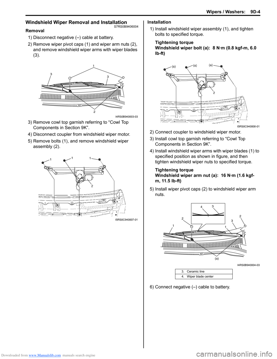
2) Remove wiper pivot caps (1) and wiper arm nuts (2), and remove windshield wiper arms with wiper blades
(3).
3) Remove cowl top garnish referring to “Cowl Top Components in Section 9K”.
4) Disconnect coupler from windshield wiper motor.
5) Remove bolts (1), and remove windshield wiper assembly (2). Installation
1) Install windshield wiper assembly (1), and tighten bolts to specified torque.
Tightening torque
Windshield wiper bolt (a): 8 N·m (0.8 kgf-m, 6.0
lb-ft)
2) Connect coupler to windshield wiper motor.
3) Install cowl top garnish referring to “Cowl Top
Components in Section 9K”.
4) Install windshield wiper arms with wiper blades (1) to specified position as shown in figure, and then
tighten windshield wiper nuts to specified torque.
Tightening torque
Windshield wiper arm nut (a): 16 N·m (1.6 kgf-
m, 11.5 lb-ft)
5) Install wiper pivot caps (2 ) to windshield wiper arm
nuts.
6) Connect negative (–) cable to battery.
1 3
3
2
I4RS0B940003-03
I5RS0C940007-01
3. Ceramic line
4. Wiper blade center
I5RS0C940008-01
2
2 3
3
4
1
1
(a)
I4RS0B940004-03
Page 1322 of 1496
Downloaded from www.Manualslib.com manuals search engine 9D-5 Wipers / Washers:
Windshield Wiper Motor InspectionS7RS0B9406005
NOTE
Make sure that battery voltage is 12 V or
more.
1) Disconnect negative (–) cable at battery.
2) Remove windshield wiper arms with wiper blades
referring to “Windshield Wiper Removal and
Installation”.
3) Remove cowl top garnish referring to “Cowl Top Components in Section 9K”.
4) Disconnect coupler from windshield wiper motor.
5) Reinstall windshield wiper arms with wiper blade. For
details, refer to Step 4) of “Installation” in “Windshield
Wiper Removal and Installation”.
6) Check windshield wiper motor for operation as
follows
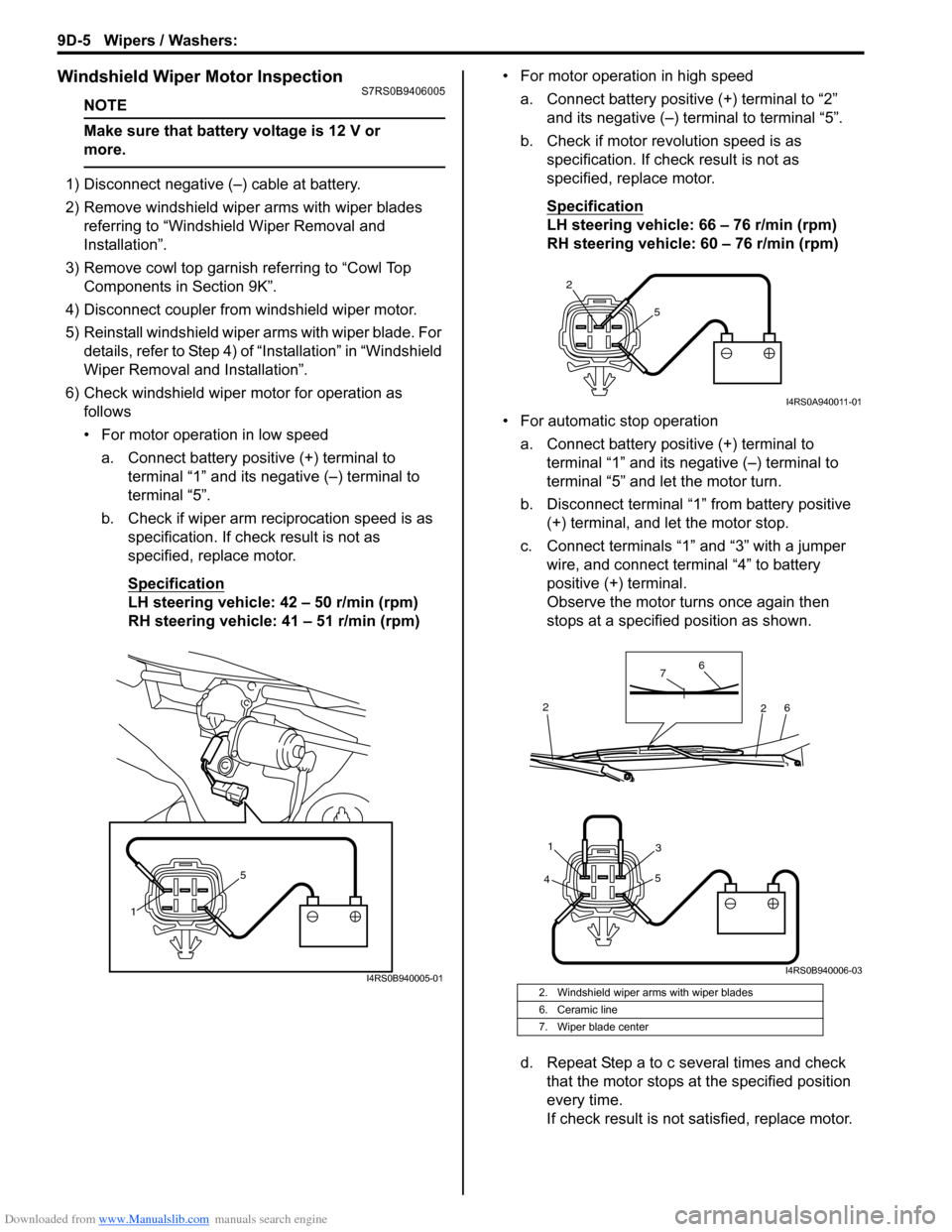
• For motor operation in low speed
a. Connect battery positive (+) terminal to terminal “1” and its negative (–) terminal to
terminal “5”.
b. Check if wiper arm reciprocation speed is as specification. If check result is not as
specified, replace motor.
Specification
LH steering vehicle: 42 – 50 r/min (rpm)
RH steering vehicle: 41 – 51 r/min (rpm) • For motor operation in high speed
a. Connect battery positive (+) terminal to “2” and its negative (–) terminal to terminal “5”.
b. Check if motor revolution speed is as specification. If chec k result is not as
specified, replace motor.
Specification
LH steering vehicle: 66 – 76 r/min (rpm)
RH steering vehicle: 60 – 76 r/min (rpm)
• For automatic stop operation a. Connect battery positive (+) terminal to terminal “1” and its negative (–) terminal to
terminal “5” and let the motor turn.
b. Disconnect terminal “1” from battery positive (+) terminal, and let the motor stop.
c. Connect terminals “1” and “3” with a jumper wire, and connect terminal “4” to battery
positive (+) terminal.
Observe the motor turns once again then
stops at a specified position as shown.
d. Repeat Step a to c several times and check that the motor stops at the specified position
every time.
If check result is not satisfied, replace motor.
1 5
I4RS0B940005-012. Windshield wiper arms with wiper blades
6. Ceramic line
7. Wiper blade center
2
5
I4RS0A940011-01
4 5
31
6
6
7
2
2
I4RS0B940006-03