2006 SUZUKI SWIFT Manual transaxle oil
[x] Cancel search: Manual transaxle oilPage 824 of 1496

Downloaded from www.Manualslib.com manuals search engine 5B-10 Manual Transmission/Transaxle:
16) Remove engine under covers.
17) Support transaxle with transmission jack.
18) Remove transaxle to engine bolts and nut of lower side.
19) Remove engine left mounting (1) with bracket (2).
20) Remove engine rear mounting bracket bolts (1).
21) Remove other attached parts from transaxle, if any.
22) Pull transaxle so as to disconnect input shaft from clutch disc, and then lower it. Remounting
CAUTION!
• Care should be taken not to scratch oil
seal lip with drive shaft while raising
transaxle.
• Do not hit drive shaft joint with hammer when installing it into differential gear.
Reverse dismounting procedure for remounting noting
the following.
• Tighten each bolts and nuts to specified torque referring to “Manual Transaxle Unit Components”.
• Set each clamp for wiring securely.
• Fill transaxle oil referring to “Manual Transaxle Oil
Change”.
• Fill coolant referring to “Cooling System Flush and
Refill in Section 1F”.
• Install hook (1) and ground cable (2) at specified position as shown in figure.
• Connect battery and check function of engine, clutch
and transaxle.
1
2
I4RS0A520021-01
1
I4RS0A520022-01
3. Transaxle side cover 4. Transaxle left case
90
1
2 3
4
I4RS0A520023-01
Page 825 of 1496

Downloaded from www.Manualslib.com manuals search engine Manual Transmission/Transaxle: 5B-11
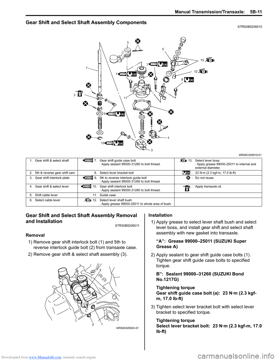
Gear Shift and Select Shaft Assembly ComponentsS7RS0B5206010
Gear Shift and Select Shaft Assembly Removal
and Installation
S7RS0B5206011
Removal1) Remove gear shift interlock bolt (1) and 5th to reverse interlock guide bolt (2) from transaxle case.
2) Remove gear shift & select shaft assembly (3). Installation
1) Apply grease to select lever shaft bush and select lever boss, and install gear shift and select shaft
assembly with new gasket into transaxle.
“A”: Grease 99000–25011 (SUZUKI Super
Grease A)
2) Apply sealant to gear shift guide case bolts (1). Tighten gear shift guide case bolts to specified
torque.
B”: Sealant 99000–31260 (SUZUKI Bond
No.1217G)
Tightening torque
Gear shift guide case bolt (a): 23 N·m (2.3 kgf-
m, 17.0 lb-ft)
3) Tighten select lever brac ket bolt with select lever
bracket to specified torque.
Tightening torque
Select lever bracket bolt: 23 N·m (2.3 kgf-m, 17.0
lb-ft)
I6RS0C520010-01
1. Gear shift & select shaft 7. Gear shift guide case bolt
: Apply sealant 99000-31260 to bolt thread. 13. Select lever boss
: Apply grease 99000-25011 to internal and
external diameter.
2. 5th & reverse gear shift cam 8. Select lever bracket bolt : 23 N⋅m (2.3 kgf-m, 17.0 lb-ft)
3. Gear shift interlock plate 9. 5th to reverse interlock guide bolt
: Apply sealant 99000-31260 to bolt thread. : Do not reuse.
4. Gear shift & select lever 10. Gear shift interlock bolt
: Apply sealant 99000-31260 to bolt thread. : Apply transaxle oil.
5. Shift cable lever 11. Guide case
6. Select cable lever 12. Select lever shaft bush
: Apply grease 99000-25011 to whole area of bush.
3
12I4RS0A520024-01
Page 827 of 1496

Downloaded from www.Manualslib.com manuals search engine Manual Transmission/Transaxle: 5B-13
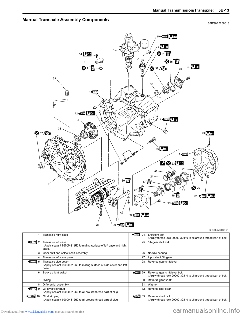
Manual Transaxle Assembly ComponentsS7RS0B5206013
I6RS0C520005-01
1. Transaxle right case 24. Shift fork bolt
: Apply thread lock 99000-32110 to all around thread part of bolt.
2. Transaxle left case : Apply sealant 99000-31260 to mating surface of left case and right
case. 25. 5th gear shift fork
3. Gear shift and select shaft assembly 26. Needle bearing
4. Transaxle left case plate 27. Input shaft 5th gear
5. Transaxle side cover : Apply sealant 99000-31260 to mating surface of side cover and left
case. 28. Reverse gear shift lever
6. Back up light switch 29. Reverse gear shift lever bolt
: Apply thread lock 99000-32110 to all around thread part of bolt.
7. O-ring 30. Reverse gear shaft
8. Differential assembly 31. Washer
9. Oil level/filler plug : Apply sealant 99000-31260 to all around thread part of plug. 32. Reverse idler gear
10. Oil drain plug : Apply sealant 99000-31260 to all around thread part of plug. 33. Reverse shaft bolt
: Apply thread lock 99000-32110 to all around thread part of bolt.
Page 828 of 1496

Downloaded from www.Manualslib.com manuals search engine 5B-14 Manual Transmission/Transaxle:
Fifth Gear Disassembly and AssemblyS7RS0B5206014
Disassembly1) Remove cover bolts and take off transaxle side cover (1).
CAUTION!
Care should be taken not to distort side cover
when it is removed from left case.
2) Using snap ring pliers, remove circlip (1).
3) Remove 5th shift fork bolt (2).
4) Remove gear shift fork (3), synchronizer sleeve &
hub assembly (4), synchron izer levers, synchronizer
ring and input shaft 5th gear (5) all together. Use
gear puller for removal if spline fitting of hub is tight. 5) Unfasten caulking of countershaft nut (2), install
input shaft 5th gear (1) and special tool to stop
rotation of shafts, and then remove countershaft nut
(2).
Special tool
(A): 09927–76060
6) Remove input shaft 5th gear, needle bearing and then countershaft 5th gear (1). Gear puller (2) would
be necessary if spline fitting of countershaft 5th gear
is tight.
11. Sensor cap 34. Washer
12. Oil gutter bolt : Apply thread lock 99000-32110 to all around thread part of bolt. 35. Side bearing retainer
13. Left case plate bolts : Apply thread lock 99000-32110 to all around thread part of bolt. 36. O-ring
14. Sensor cap bolt 37. Oil seal
: Apply grease 99000-25011 to oil seal lip.
15. Side cover bolts 38. Outer race
16. Transaxle case bolts 39. Breather hose
17. 5th speed synchronizer ring 40. Side bearing retainer bolt
18. 5th speed synchronizer lever : 23 N⋅m (2.3 kgf-m, 17.0 lb-ft)
19. 5th speed synchronizer sleeve & hub : 21 N⋅m (2.1 kgf-m, 15.5 lb-ft)
20. Circlip :10 N⋅m (1.0 kgf-m, 7.5 lb-ft)
21. Bearing set shim : 100 N⋅m (10.0 kgf-m, 72.5 lb-ft)
22. Countershaft 5th gear : Do not reuse.
23. Countershaft nut : After tightening nut to specified torque, caulk nut securely. : Apply transaxle oil.
I4RS0A520027-01
342
1
5
I4RS0A520028-01
1(A)
2
I3RM0B521014-01
I4RS0A520041-01
Page 829 of 1496

Downloaded from www.Manualslib.com manuals search engine Manual Transmission/Transaxle: 5B-15
Assembly1) Assemble 5th speed synchronizer sleeve (1), hub (2), 5th speed synchronizer levers (3) and
synchronizer ring (4) as follows.
a) Install hub (1) to 5th speed synchronizer sleeves (2) in specified direction as shown in figure.
b) Fit 5th speed synchronizer levers (1) to hub (2) as shown in figure.
NOTE
Align protrusion A of 5th speed synchronizer
levers (1) with groove of hub (2).
c) Install synchronizer ring (1) to hub (2) as shown in figure.
2) Install 5th gear (1) to countershaft facing machined boss A inward.
3) Install needle bearing to input shaft, apply oil then install input shaft 5th gear (1) and special tool to stop
shaft rotation.
Special tool
(A): 09927–76060
4) Tighten new countershaft nut (2) to specified torque, and caulk countershaft nut securely.
Tightening torque
Countershaft nut (a): 100 N·m (10.0 kgf-m, 72.5
lb-ft)
A: Chamfered side B: Long boss
I4RH01520054-01
1
2
B
A
I4RH01520048-01
1A
2
A
I4RH01520049-01
A: Machined boss (Inside)
B: No machining (Outside)
1
2
I4RH01520055-01
I2RH01520088-01
1
(A)
2, (a)
I3RM0B521016-01
Page 832 of 1496

Downloaded from www.Manualslib.com manuals search engine 5B-18 Manual Transmission/Transaxle:
18) Remove differential bearing shim.
19) Remove differential side bearing outer race from left case (1) using special tools.
Special tool
(A): 09924–74510
(B): 09926–27610
20) Remove differential gear assembly (1) from right case (2).
Reassembly 1) Install differential assembly (1) into right case (2). 2) Join input shaft assembly (5), countershaft assembly
(4), low speed gear shift shaft (2) and high speed
gear shift shaft (3) assemblies all together, then
install them into right case (1).
CAUTION!
Take care not to damage oil seal lip by input
shaft, or oil leakage may take place.
NOTE
• Input shaft right bearing on shaft can be
installed into right case tapping shaft with
plastic hammer.
• Check to make sure that countershaft is engaged with final g ear while installing.
3) Install 5th & reverse gear shift shaft (1) with 5th &
reverse gear shift guide shaft (2) into right case (5).
Reverse gear shift arm (4) has to be joined with
reverse gear shift lever (3) at the same time.
(A)
(B)
1
I4RS0A520035-01
I6RS0C520006-02
I6RS0C520006-02
I2RH01520080-01
I2RH01520081-01
Page 835 of 1496

Downloaded from www.Manualslib.com manuals search engine Manual Transmission/Transaxle: 5B-21
c) Install differential side bearing shim to left case (4).
d) Apply oil to new O-ring of side bearing retainer (3), and install side bea ring retainer with new O-
ring to left case.
e) Tighten side bearing retainer bolts (1) to specified torque.
NOTE
Install side bearing retainer with its punch
mark (2) facing upward.
Tightening torque
Side bearing retainer bolt (a): 23 N·m (2.3
kgf-m, 17.0 lb-ft)
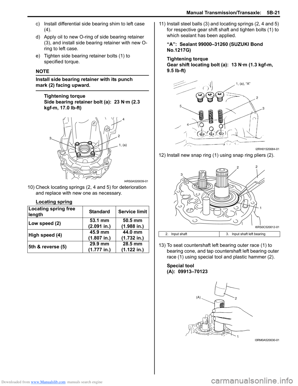
10) Check locating springs (2, 4 and 5) for deterioration and replace with new one as necessary.
Locating spring
11) Install steel balls (3) and locating springs (2, 4 and 5) for respective gear shift shaft and tighten bolts (1) to
which sealant has been applied.
“A”: Sealant 99000–31260 (SUZUKI Bond
No.1217G)
Tightening torque
Gear shift locating bolt (a): 13 N·m (1.3 kgf-m,
9.5 lb-ft)
12) Install new snap ring (1) using snap ring pliers (2).
13) To seat countershaft left bearing outer race (1) to bearing cone, and tap countershaft left bearing outer
race (1) using special tool and plastic hammer (2).
Special tool
(A): 09913–70123
Locating spring free
length
Standard Service limit
Low speed (2) 53.1 mm
(2.091 in.) 50.5 mm
(1.988 in.)
High speed (4) 45.9 mm
(1.807 in.) 44.0 mm
(1.732 in.)
5th & reverse (5) 29.9 mm
(1.777 in.) 28.5 mm
(1.122 in.)
1, (a)
2
4
3
I4RS0A520039-01
2. Input shaft 3. Input shaft left bearing
I2RH01520084-01
1
2
2
3
I6RS0C520012-01
I3RM0A520030-01
Page 837 of 1496

Downloaded from www.Manualslib.com manuals search engine Manual Transmission/Transaxle: 5B-23
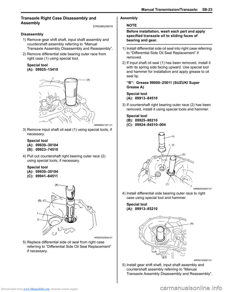
Transaxle Right Case Disassembly and
Assembly
S7RS0B5206016
Disassembly1) Remove gear shift shaft, input shaft assembly and countershaft assembly referring to “Manual
Transaxle Assembly Disassembly and Reassembly”.
2) Remove differential side bearing outer race from right case (1) using special tool.
Special tool
(A): 09925–15410
3) Remove input shaft oil seal (1) using special tools, if necessary.
Special tool
(A): 09930–30104
(B): 09923–74510
4) Pull out countershaft right bearing outer race (2) using special tools, if necessary.
Special tool
(A): 09930–30104
(C): 09941–64511
5) Replace differential side oil seal from right case referring to “Differential Side Oil Seal Replacement”
if necessary. Assembly
NOTE
Before installation, wash each part and apply
specified transaxle oil to sliding faces of
bearing and gear.
1) Install differential side oil seal into right case referring
to “Differential Side O il Seal Replacement” if
removed.
2) If input shaft oil seal (1) has been removed, install it with its spring side facing upward. Use special tool
and hammer for installation and apply grease to oil
seal lip.
“B”: Grease 99000–25011 (SUZUKI Super
Grease A)
Special tool
(A): 09913–84510
3) If countershaft right bearing outer race (2) has been removed, install it using special tools and hammer.
Special tool
(B): 09925–98210
(C): 09924–84510–004
4) Install differential side bearing outer race to right case using special tool and hammer.
Special tool
(A): 09913–85210
5) Install gear shift shaft, input shaft assembly and countershaft assembly referring to “Manual
Transaxle Assembly Disassembly and Reassembly”.
(A)1
I3RM0B521021-01
I4RS0A520040-01
I3RM0A520047-01
(A)
I4RH01520027-01