2006 SUBARU IMPREZA WRX clock setting
[x] Cancel search: clock settingPage 119 of 365

3-6 Instruments and controls
Hazard warning flasher
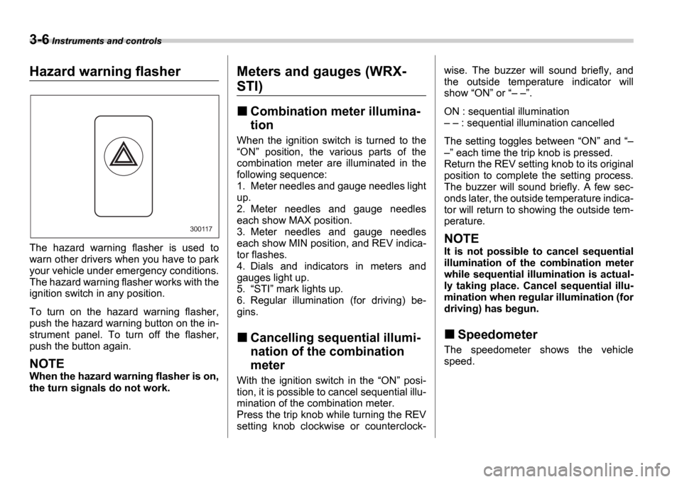
The hazard warning flasher is used to
warn other drivers when you have to park
your vehicle under emergency conditions.
The hazard warning flasher works with the
ignition switch in any position.
To turn on the hazard warning flasher,
push the hazard warning button on the in-
strument panel. To turn off the flasher,
push the button again.
NOTE
When the hazard warning flasher is on,
the turn signals do not work.
Meters and gauges (WRX-
STI)
Combination meter illumina-
tion
When the ignition switch is turned to the ON position, the various parts of the
combination meter are illuminated in the
following sequence:
1. Meter needles and gauge needles light
up.
2. Meter needles and gauge needles
each show MAX position.
3. Meter needles and gauge needles
each show MIN position, and REV indica-
tor flashes.
4. Dials and indicators in meters and
gauges light up.
5. STI mark lights up.
6. Regular illumination (for driving) be-
gins.
Cancelling sequential illumi-
nation of the combination
meter
With the ignition switch in the ON posi-
tion, it is possible to cancel sequential illu-
mination of the combination meter.
Press the trip knob while turning the REV
setting knob clockwise or counterclock- wise. The buzzer will sound briefly, and
the outside temperature indicator will
show
ON or .
ON : sequential illumination : sequential illumination cancelled
The setting toggles between ON and
each time the trip knob is pressed.
Return the REV setting knob to its original
position to complete the setting process.
The buzzer will sound briefly. A few sec-
onds later, the outside temperature indica-
tor will return to showing the outside tem-
perature.
NOTE
It is not possible to cancel sequential
illumination of the combination meter
while sequential illumination is actual-
ly taking place. Cancel sequential illu-
mination when regular illumination (for
driving) has begun.
Speedometer
The speedometer shows the vehicle
speed.
300117
Page 123 of 365

3-10 Instruments and controls
Setting the alarm-level en-
gine speed
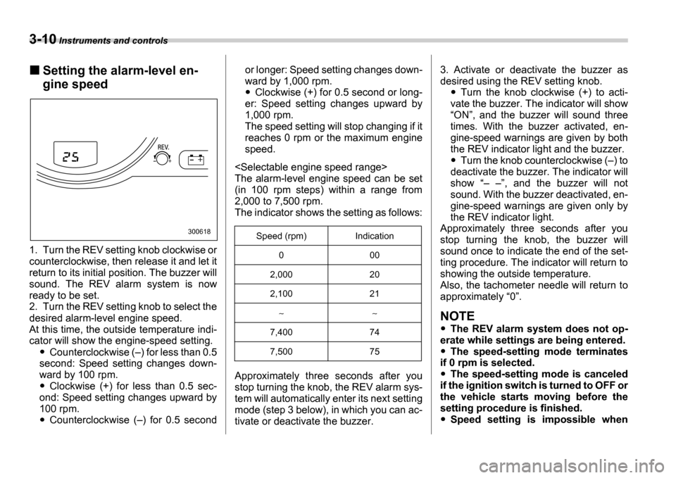
1. Turn the REV setting knob clockwise or
counterclockwise, then release it and let it
return to its initial position. The buzzer will
sound. The REV alarm system is now
ready to be set.
2. Turn the REV setting knob to select the
desired alarm-level engine speed.
At this time, the outside temperature indi-
cator will show the engine-speed setting.
Counterclockwise ( ) for less than 0.5
second: Speed setting changes down-
ward by 100 rpm.
Clockwise (+) for less than 0.5 sec-
ond: Speed setting changes upward by
100 rpm.
Counterclockwise ( ) for 0.5 second or longer: Speed setting changes down-
ward by 1,000 rpm.
Clockwise (+) for 0.5 second or long-
er: Speed setting changes upward by
1,000 rpm.
The speed setting will stop changing if it
reaches 0 rpm or the maximum engine
speed.
The alarm-level engine speed can be set
(in 100 rpm steps) within a range from
2,000 to 7,500 rpm.
The indicator shows the setting as follows:
Approximately three seconds after you
stop turning the knob, the REV alarm sys-
tem will automatically enter its next setting
mode (step 3 below), in which you can ac-
tivate or deactivate the buzzer. 3. Activate or deactivate the buzzer as
desired using the REV setting knob.Turn the knob clockwise (+) to acti-
vate the buzzer. The indicator will show ON , and the buzzer will sound three
times. With the buzzer activated, en-
gine-speed warnings are given by both
the REV indicator light and the buzzer.
Turn the knob counterclockwise ( ) to
deactivate the buzzer. The indicator will
show , and the buzzer will not
sound. With the buzzer deactivated, en-
gine-speed warnings are given only by
the REV indicator light.
Approximately three seconds after you
stop turning the knob, the buzzer will
sound once to indicate the end of the set-
ting procedure. The indicator will return to
showing the outside temperature.
Also, the tachometer needle will return to
approximately 0 .
NOTE
The REV alarm system does not op-
erate while settings are being entered.
The speed-setting mode terminates
if 0 rpm is selected.
The speed-setting mode is canceled
if the ignition switch is turned to OFF or
the vehicle starts moving before the
setting procedure is finished.
Speed setting is impossible when
300618Speed (rpm) Indication
0 00
2,000 20
2,100 21
7,400 74
7,500 75
Page 155 of 365

4-6 Climate control
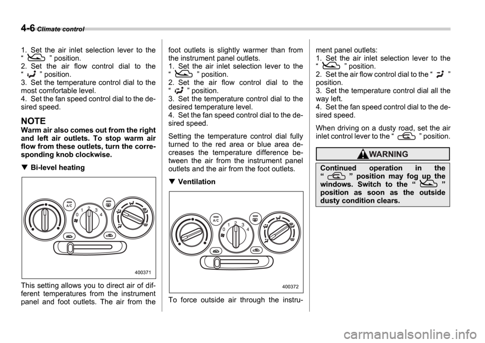
1. Set the air inlet selection lever to the
position.
2. Set the air flow control dial to the
position.
3. Set the temperature control dial to the
most comfortable level.
4. Set the fan speed control dial to the de-
sired speed.
NOTE
Warm air also comes out from the right
and left air outlets. To stop warm air
flow from these outlets, turn the corre-
sponding knob clockwise.
Bi-level heating
This setting allows you to direct air of dif-
ferent temperatures from the instrument
panel and foot outlets. The air from the foot outlets is slightly warmer than from
the instrument panel outlets.
1. Set the air inlet selection lever to the
position.
2. Set the air flow control dial to the
position.
3. Set the temperature control dial to the
desired temperature level.
4. Set the fan speed control dial to the de-
sired speed.
Setting the temperature control dial fully
turned to the red area or blue area de-
creases the temperature difference be-
tween the air from the instrument panel
outlets and the air from the foot outlets.
Ventilation
To force outside air through the instru- ment panel outlets:
1. Set the air inlet selection lever to the
position.
2. Set the air flow control dial to the
position.
3. Set the temperature control dial all the
way left.
4. Set the fan speed control dial to the de-
sired speed.
When driving on a dusty road, set the air
inlet control lever to the position.
400371
400372
Continued operation in the
position may fog up the
windows. Switch to the
position as soon as the outside
dusty condition clears.
Page 176 of 365

Audio 5-13
CONTINUED
starting from bass control mode. (When
the radio is first turned on, the control
mode is in the volume control.)
Fader and balance control
The volume control dial (8) normally func-
tion as volume control. The dial become
the controls for Fader or Balance when
you select the appropriate fader and bal-
ance control mode.
Choose desired setting for each mode by
turning the volume control dial. The con-
trol function returns to volume control
mode after approximately 5 seconds.
To change control modes: Each brief
press of the BAL button (4) changes
control modes in the following sequence
starting from fader control mode. (When
the radio is turned on, the control mode is
in the volume control.)
Display illumination dimness can-
cellation (BRIGHT)
The brightness of the radio display dims
when the light switch is in the or
positions. If this makes the display
difficult to read, press the volume dial for
more than 1.5 seconds to return the dis-
play to original brightness.
Subsequently pressing the volume dial
again for more than 1.5 seconds or if you
can safely do so, turning the light switch to
the OFF position and back to the
or position makes the radio display
dim again.
FM/AM selection button
Push the FM (1) or AM (2) button when
the radio is off to turn on the radio.
Push the FM or AM button when the ra-
dio is on to select FM1, FM2 or AM recep-
tion.
Stereo indicator
The stereo indicator ST will come on
when an FM stereo broadcast is received.
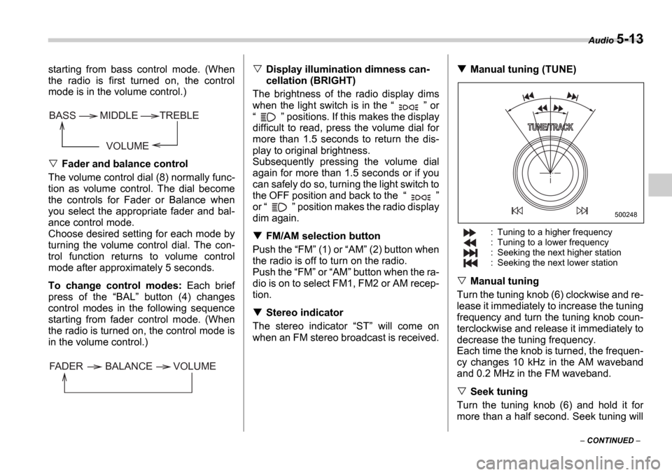
Manual tuning (TUNE)
: Tuning to a higher frequency
: Tuning to a lower frequency
: Seeking the next higher station
: Seeking the next lower station
Manual tuning
Turn the tuning knob (6) clockwise and re-
lease it immediately to increase the tuning
frequency and turn the tuning knob coun-
terclockwise and release it immediately to
decrease the tuning frequency.
Each time the knob is turned, the frequen-
cy changes 10 kHz in the AM waveband
and 0.2 MHz in the FM waveband.
Seek tuning
Turn the tuning knob (6) and hold it for
more than a half second. Seek tuning will
VOLUME
BASS TREBLE
MIDDLE
FADER BALANCE VOLUME
500248