Page 174 of 444
0-12
RODIUS 2007.07
0000-00
ELECTRIC GENERAL
5. WIRING HARNESS ARRANGEMENT
Page 222 of 444
0-10
RODIUS 2007.07
8010-10
CLUSTER
3) Fuel Level Gauge
The fuel level gauge displays the resistance value of the float on the fuel sender in the fuel tank
through a pointer. Note that this vehicle doesn’t have a service hole for checking the fuel
sender connector in the fuel tank.
The fuel sender and its connector can be checked and replaced only when the fuel tank is
removed. The power supply and resistance value should be measured at the connector in front
of the fuel sender (refer to wiring diagram).
When the power supply and output resistance are normal, the float operation by fuel level may
be defective; if so, replace the fuel sender.
Tolerance and resistance value by indicating angle
This table shows the tolerance and resistance value changes by fuel level in normal conditions.
Therefore, the differences that can be occurred by the road conditions and fuel fluctuations are
ignored.
Page 223 of 444
0-11
CLUSTER
RODIUS 2007.07
8010-10
4) Coolant Temperature Gauge
The coolant temperature gauge displays the coolant temperature with a pointer. The angle of
pointer that changes by coolant temperature is as shown below.
Measurement of coolant temperature sensor resistance
Measure the resistance between the terminal and the ground with an ohmmeter and replace i
f
the resistance is out of specified range.
Resistance value by coolant temperature:
20°C : 2449 Ω ±5 %
50°C : 826 Ω ±5 %
80°C : 321 Ω ±5 %
100°C : 112 Ω ±5 %
When the resistance value by coolant temperature is within the specified range, check
thermostat, water pump, radiator related coolant circuit for normal operation. Also, check the
wiring harnesses and connectors for proper connection.
-40 040° °°
Page 329 of 444
0-11
ABS SYSTEM
RODIUS 2007.07
4892-01
Use only DOT-3 equivalent hydraulic brake fluid. The use of DOT-5 (silicone) brake fluid is
not recommended. Reduced brake performance or durability may result.
Avoid spilling brake fluid on any the vehicle’s painted surfaces, wiring, cables or
electrical connectors. Brake fluid will damage paint and electrical connections. If any fluid is
spilled on the vehicle, flush the area with water to lessen the damage.
Page 334 of 444

0-16
RODIUS 2007.07
4892-01
ABS SYSTEM
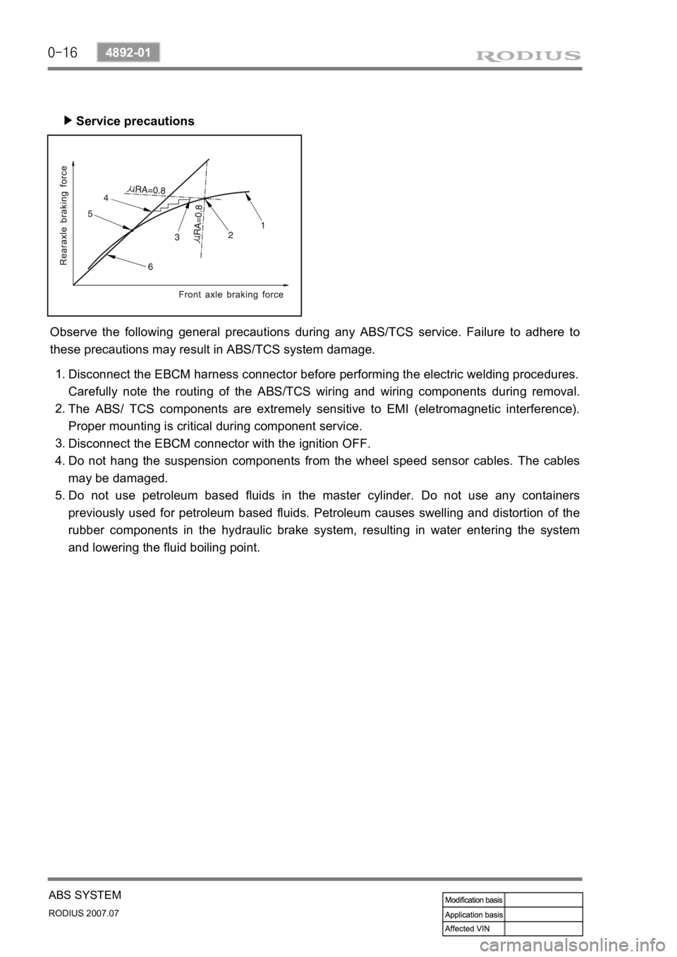
Service precautions ▶
Observe the following general precautions during any ABS/TCS service. Failure to adhere to
these precautions may result in ABS/TCS system damage.
Disconnect the EBCM harness connector before performing the electric welding procedures.
Carefully note the routing of the ABS/TCS wiring and wiring components during removal.
The ABS/ TCS components are extremely sensitive to EMI (eletromagnetic interference).
Proper mounting is critical during component service.
Disconnect the EBCM connector with the ignition OFF.
Do not hang the suspension components from the wheel speed sensor cables. The cables
may be damaged.
Do not use petroleum based fluids in the master cylinder. Do not use any containers
previously used for petroleum based fluids. Petroleum causes swelling and distortion of the
rubber components in the hydraulic brake system, resulting in water entering the system
and lowering the fluid boiling point. 1.
2.
3.
4.
5.
Page 361 of 444
0-10
RODIUS 2007.07
6810-20
AIR CONDITIONING SYSTEM
2. AIR CONDITIONER MODULE WIRING AND LAYOUT
1) Front Air Conditioner Module
Wiring layout
Components
Air source selection
door actuatorAir conditioner filterEvaporator
Blower
motor
Blower high
speed relay
Heater core
Page 362 of 444
0-11
AIR CONDITIONING SYSTEM
RODIUS 2007.07
6810-20
2) Rear Air Conditioner Module
Wiring layout
Components
Roof air conditioner duct
Blower motor
EvaporatorAir mixer door actuator
Rear floor heater duct
Mixer door
Heater coreHeater &
air conditioner pipes
Page 366 of 444
0-15
AIR CONDITIONING SYSTEM
RODIUS 2007.07
6810-20
(3) Inspection
If the active incar sensor defect code (DTC 1) and the humidity sensor defect code (DTC 10)
are set, check as below:
Air conditioner controller
Air conditioner controller connector (based on wiring) AIH sensor (based on sensor)
Active incar sensor
▶
Remove the integrated AIH sensor and measure the resistance between terminal No. 5 and
6 on the sensor connector. (standard: approx. 25°C, 2.2 kΩ)
If the measured value is out of the specified range, replace the AIH sensor. If the measured
values are within the specified range, check as below.
Turn the ignition switch to ON position and measure the voltage to active incar sensor from
the FATC controller connector. (standard: approx. 2 V at 25°C)
If the voltage value cannot be measured, check the circuit for open. If the measured value is
within the specified range, replace the FATC controller.
1.
2.
3.
4.