Page 216 of 444
0-4
RODIUS 2007.07
8010-10
CLUSTER
2. DESCRIPTIONS OF INDICATOR DISPLAY
1. Immobilizer indicator
2. Glow indicator
3. Winter mode indicator
4. Left turn signal indicator
5. Auto shift indicator (for automatic transmission)
6. Right turn signal indicator
7. Harzard indicator*
8. Engine check warning light
9. Cruise control indicator*
10. 4WD CHECK warning light
11. 4WD HIGH indicator
12. 4WD LOW indicator
13. Brake warning light14. Battery charge warning light
15. Seat belt reminder
16. Low fuel level warning light
17. Heated glass indicator
18. Door open warning light
19. High beam indicator
20. Engine oil pressure warning light
21. Air bag warning light
22. Water separator warning light
23. ABS warning light
24. EBD warning light
25. ESP warning light
Page 221 of 444

0-9
CLUSTER
RODIUS 2007.07
8010-10
2) Speedometer
The speedometer indicates the vehicle speed by calculating the signals from the rear right
wheel speed sensor through ABS or ESP unit.
If the speedometer pointer vibrates, stands at a certain range or sounds abnormal noise, there
could be defectives in speedometer. However, these symptoms also could be appeared when
the tire has uneven wear, different tire inflation pressures or different tire specifications.
Perform the speedometer test regarding the tolerance as described. However, it is not simila
r
simple work in field due to lack of measuring conditions such as test equipment and
preciseness.
Check the allowable tolerance of the speedometer and operations of the trip odometer by
using a tester.
Check if the speedometer pointer is shaking and the abnormal noise sounds.
Eliminate the hysteresis by tapping the speedometer. 1.
2.
3.
The allowable tolerance increases when the tires are worn or the tire pressure is out of
specified range. -
Page 224 of 444
0-12
RODIUS 2007.07
8010-10
CLUSTER
5) TRIP ODOmeter (TRIP A, TRIP B) and ODOmeter
Reset button
Press and hold (over 1 sec.)
Trip odometer “TRIP A” and “TRIP B” will be reset to 0. (However, only the
corresponding driving range will be set to 0.) *
Press shortly (between 0.1 ~ 1 sec.)
The mode changes in order as shown in the figure. *
Page 301 of 444
0-8
RODIUS 2007.07
4830-01
BRAKS SYSTEM
6) Master Cylider & Booster
ABS system is basically equipped to STAVIC.
Vehicle which adapted ESP system in option has two pressure sensors under master cylinder
and these two sensor are used for BAS (Brake Assist System) system.
Do not disassemble the brake oil pressure sensors These can not be reinstalled of
disassembled.
After reinstall the reserver tank perform a air bleeding of brake system
-
-
Vehicle with ESP Vehicle with ABS
Brake fluid reservoir tank Master cylinder
Page 302 of 444
0-3
ESP SYSTEM
RODIUS 2007.07
4892-01
8510-56ABS/ESP System
1. SPECCIFICATIONS OF ESP SYSTEM
1) Specifications Of Pressure Sensor
2) Specifications Of Sensor Cluster
(sensor cluster: yaw rate sensor + lateral acceleration sensor + Longitudinal acceleration sensor)
3) Specifications Of Wheel Speed Sensor
4) Specifications Of Steering Wheel Angle sensor
Page 303 of 444
0-4
RODIUS 2007.07
4892-01
ESP SYSTEM
1. COMPONENTS AND LOCATIONS
2WD vehicle has the longitudinal sensor in the HECU.
1. HECU: (Hydraulic &
Engine conrol unit) 2. Pressure sensor 3. Wheel speed sensor
4. Sensor cluster:
(Yaw rate + lateral sensor + longitudinal sensor) 5. Steering wheel angle
sensor 6. ESP off switch (Electronic
Stability Program Switch) ESP Warning lamp
Page 304 of 444
0-5
ESP SYSTEM
RODIUS 2007.07
4892-01
2. INPUT AND OUTPUT DIAGRAM
Page 305 of 444

0-6
RODIUS 2007.07
4892-01
ESP SYSTEM
3. ESP SYSTEM DESCRIPTION
1) Principle of ESP
ESP (Electronic Stability Program) recognizes critical driving conditions, such as panic
reactions in dangerous situations, and stabilizes the vehicle by wheel-individual braking and
engine control intervention with no need for actuating the brake. This system is developed to
help the driver avoid the danger of losing the control of the vehicle stability due to under-
steering or over-steering during cornering.
The yaw rate sensor, lateral sensor and longitudinal sensor in the sensor cluster and the
steering wheel angle sensor under the steering column detect the spin present at any wheels
during over-steering, under-steering or cornering. The ESP ECU controls against over-steering
or under-steering during cornering by controlling the vehicle stability using the input values from
the sensors and applying the brakes independently to the corresponding wheels.
The system also controls during cornering by detecting the moment right before the spin and
automatically limiting the engine output (coupled with the ASR system).
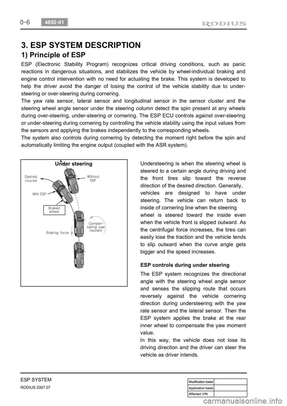
Understeering is when the steering wheel is
steered to a certain angle during driving and
the front tires slip toward the reverse
direction of the desired direction. Generally,
vehicles are designed to have unde
r
steering. The vehicle can return back to
inside of cornering line when the steering
wheel is steered toward the inside even
when the vehicle front is slipped outward.
As
the centrifugal force increases, the tires can
easily lose the traction and the vehicle tends
to slip outward when the curve angle gets
bigger and the speed increases. Under steering
ESP controls during under steering
The ESP system recognizes the directional
angle with the steering wheel angle senso
r
and senses the slipping route that occurs
reversely against the vehicle cornering
direction during understeering with the yaw
rate sensor and the lateral sensor. Then the
ESP system applies the brake at the rea
r
inner wheel to compensate the yaw moment
value.
In this way, the vehicle does not lose its
driving direction and the driver can steer the
vehicle as driver intends.