2006 SKODA ROOMSTER ESP
[x] Cancel search: ESPPage 59 of 274

Lights and Visibility
58
– Pull the light switch out to the second detent . The fog
lights* light up at the same time.
If the vehicle is not fitted with fog lights*, the rear fog light is switched on
by turning the light switch to the position and is pulled out directly to
the position . This switch does not have two positions, but only one
position.
The rear fog light warning light
⇒ page 27 lights up in the instrument
cluster when the fog light is switched off.
Only the rear fog light of the trailer lights up if the vehicle is fitted with a
towing device from Škoda original accessories and when you are
towing a trailer which is fitted with the rear fog light.
Caution
The rear fog light should only be switched on if visibility is particularly poor
(conform with any varying legal provisions) to avoid dazzling vehicles
behind your vehicle.
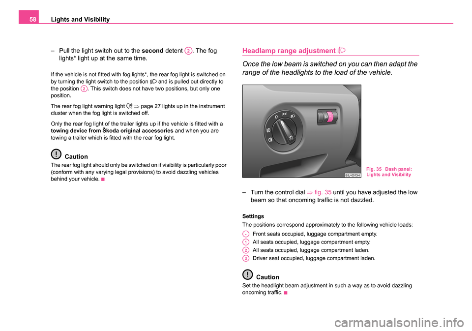
Headlamp range adjustment
Once the low beam is switched on you can then adapt the
range of the headlights to the load of the vehicle.
– Turn the control dial ⇒fig. 35 until you have adjusted the low
beam so that oncoming traffic is not dazzled.
Settings
The positions correspond approximately to the following vehicle loads:
Front seats occupied, luggage compartment empty.
All seats occupied, luggage compartment empty.
All seats occupied, luggage compartment laden.
Driver seat occupied, luggage compartment laden.
Caution
Set the headlight beam adjustment in such a way as to avoid dazzling
oncoming traffic.
A2
A2
Fig. 35 Dash panel:
Lights and Visibility
A-
A1
A2
A3
NKO 20 A05.book Page 58 Wednesday, June 21, 2006 1:42 PM
Page 61 of 274

Lights and Visibility
60
Main beam
– Switch on the low beam.
– Push the lever forwards - the main beam and warning light in the instrument cluster come on.
– Pull the lever back into the initial position in order to switch the main beam off again.
Headlight flasher
– Pull on the lever of the steering wheel (sprung position) - the main beam and warning light in the instrument cluster come
on.
Parking light
– Switch off the ignition.
– Push the lever up or down - the right-hand or left-hand parking light is switched on.
Information concerning the function of the lights.
•The turn signal system only operates when the ignition is switched
on. The corresponding indicator light or in the instrument cluster also
flashes.
•The turn signal is automatically cancelled after negotiating a curve.
•The side light and rear light on the appropriate side of the vehicle are
switched on when the parking light is selected. The parking light function
only operates if the ignition is switched off.
•An acoustic warning signal will sound when the driver's door is opened
if the lever is not in the middle position after removing the ignition key. The
acoustic warning signal will stop just as soon as the driver's door is closed.
Caution
Use main beam or the headlight flasher only if this does not risk dazzling
other road users.
Note
Use only in accordance with the legal requirements the described lighting
and signal systems.
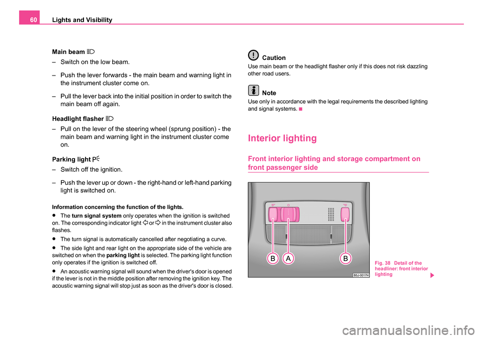
Interior lighting
Front interior lighting and storage compartment on
front passenger side
Fig. 38 Detail of the
headliner: front interior
lighting
NKO 20 A05.book Page 60 Wednesday, June 21, 2006 1:42 PM
Page 74 of 274

Seats and Stowage73
Using the systemSafetyDriving TipsGeneral MaintenanceBreakdown assistanceTechnical Data
Adjust the angle of the seat backrest
– Pull the lever ⇒page 72, fig. 52 and adjust the desired angle
of the seat backrest.
Folding seats forwards
Fold seats fully forwards and secure
– Open the guide loop for the seat belt on the side of the outer seats and put the belt tongue into the opening of the respec-
tive side trim panel - safety holder.
– Move the seat as far as possible to the rear ⇒page 72.
– Pull the lever ⇒page 72, fig. 52 and fold the seat backrest
fully fowards.
– Pull the lever ⇒fig. 53 up and then fold the seat fully forwards.
– Secure the folded forward seat with the aid of the fixing belt to a guide rod of the head restraint for the front seat ⇒fig. 54 .
Fig. 53 Folding seat
fully forwards
Fig. 54 Secure folded
forward seats
NKO 20 A05.book Page 73 Wednesday, June 21, 2006 1:42 PM
Page 102 of 274

Heating and air conditioning system 101
Using the systemSafetyDriving TipsGeneral MaintenanceBreakdown assistanceTechnical Data
The controls and can be set to any desired intermediate position.
The blower should aways be on to prevent the windows from misting up.
Note
•The whole heat output will be needed to unfrost the windscreen and
side windows. No warm air will be fed to the footwell. This can lead to
restriction of the heating comfort.
•The used air streams out through the air removal openings in the
luggage compartment.
•If the cooling system has not been switched on for a lengthy period,
odours may be produced at the evaporator because of deposits. Switch
the air conditioning system on at least once a month for approximately 5
minutes at the highest blower stage - also during the cold season of the
year - in order to remove such odours. Also open a window for a short
time.
•Please refer to the information regarding recirculated air mode
⇒ page 102.
•Have the air conditioning system cleaned by a specialist workshop.
Set Climatic
Recommended settings of Climatic controls for the respective operating
modes:
Defrosting the windscreen and side windows
•Put the control dial ⇒page 100, fig. 94 to the temperature selected
as usual by you (we recommend 22 °C)
•Blower switch in position 3 or 4
•Turn the air distribution control into the position
•Open air outlet vents 4 ⇒ page 103, fig. 95 and point towards the side
window.
Keeping windscreen and side windows demisted
We recommend that you use the following setting in cases where the
windows are misted up more than usual (e.g. when it is raining):
•Blower switch in position 2
•Turn the air distribution control into the position between and
•Open air outlet vents 4 ⇒ page 103, fig. 95 and point towards the side
window.
•Switch on the cooling system by pressing button .
Warming up the inside of the vehicle as rapidly as possible
•Control dial at the desired heat temperature
•Blower switch in position 3
•Turn the air distribution control into the position
•Open the air outlet vents 4
•We recommend that you briefly switch on the recirculated air mode
with the pushbutton . The windows can steam up in this position
however.
Heating the vehicle to a comfortable temperature
We recommend the following setting once the windows are no longer
misted up and the desired temperature has been reached:
•Control dial at the desired heat temperature
•Blower switch in position 2
•Turn the air distribution control into the position between and
•Open the air outlet vents 4
•Set the air distribution regulator as required between positions
and , if the windscreen gets misted up again.
AAAC
AA
AB
AC
AB
AC
AC
AA
AB
AC
AA
AB
AC
AC
NKO 20 A05.book Page 101 Wednesday, June 21, 2006 1:42 PM
Page 108 of 274

Heating and air conditioning system 107
Using the systemSafetyDriving TipsGeneral MaintenanceBreakdown assistanceTechnical Data
Defrosting windscreen - switching off
– Once again press the button or the button .
The temperature control is controlled automatically. More air flows out of
the air outlet vents 1 and 2.
Recirculated air mode
In recirculated air mode air is sucked out of the interior of
the vehicle and then fed back into the interior.
Recirculated air mode prevents polluted air outside the vehicle
from getting into the vehicle, for example when driving through a
tunnel or when standing in a traffic jam.
Switching recirculated air mode on
– Press button , the symbol
appears on the display.
Switching recirculated air mode off
– Once again press the button or the button , the symbol or the logo is no longer shown on the display.
WARNING
You should not leave recirculated air mode on over a longer period
of time, as “stale” air may result in fatigue in the driver and occu-
pants, divert your attention and also cause the windows to mist up.
The risk of having an accident increases. Switch recirculated air
mode off as soon as the windows begin misting up.
Note
If the windscreen mists up, press the button . After the windscreen has
been demisted, press the button .
Setting temperature
– You can set the desired interior temperature after switching on the ignition with the control dial .
You can set the interior temperature between +18°C and +29°C. The inte-
rior temperature is regulated automatically within this range. If you select
a temperature of less than +18 °C, “LO” is shown on the display. If you
select a temperature above +29 °C, “HI” is shown on the display. In both
limit positions the Climatronic operates at maximum cooling or heating
capacity, respectively. The temperature is not controlled in this case.
Lengthy and uneven distribution of the air flow out of the vents (in partic-
ular at the leg area) and large differences in temperature, for example
when getting out of the vehicle, can result in chills in sensitive persons.
Controlling blower
There are a total of seven blower stages available.
The Climatronic system controls the blower stages automatically
in line with the interior temperature. You can also, however, adapt
the blower stages manually to suit your particular needs.
– Turn the control dial ⇒page 105, fig. 96 to the left (reduce
blower speed) or right (increase blower speed).
AUTO
AUTO
AUTO
A11
A1
NKO 20 A05.book Page 107 Wednesday, June 21, 2006 1:42 PM
Page 109 of 274

Heating and air conditioning system
108
Switch off the blowers, the Climatronic is switched off and in the display
shows OFF.
The set blower speed is displayed next to the control dial when the
respective number of warning lights come on.
WARNING
•“Stale air” may result in fatigue in the driver and occupants,
reduce attention levels and also cause the windows to mist up. The
risk of having an accident increases.
•Do not switch the Climatronic system off for longer than neces-
sary.
•Switch the Climatronic system on as soon as the windows mist
up.
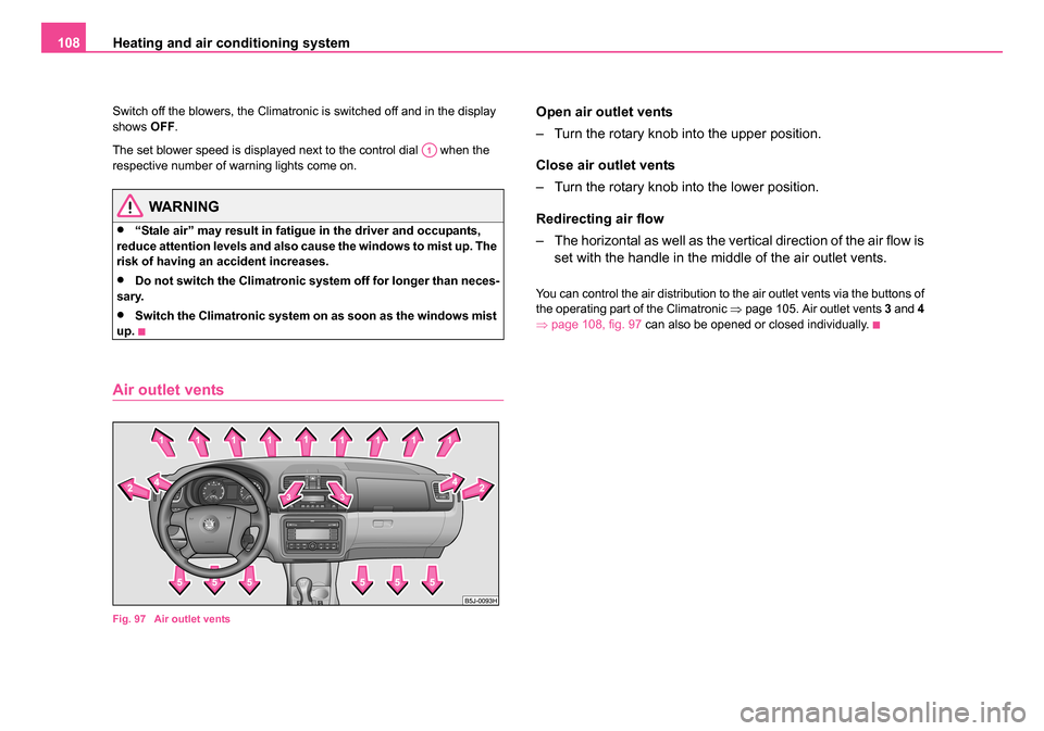
Air outlet vents
Fig. 97 Air outlet vents
Open air outlet vents
– Turn the rotary knob into the upper position.
Close air outlet vents
– Turn the rotary knob into the lower position.
Redirecting air flow
– The horizontal as well as the vertical direction of the air flow is set with the handle in the middle of the air outlet vents.
You can control the air distribution to the air outlet vents via the buttons of
the operating part of the Climatronic ⇒page 105. Air outlet vents 3 and 4
⇒ page 108, fig. 97 can also be opened or closed individually.
A1
NKO 20 A05.book Page 108 Wednesday, June 21, 2006 1:42 PM
Page 116 of 274

Starting-off and Driving115
Using the systemSafetyDriving TipsGeneral MaintenanceBreakdown assistanceTechnical Data
Parking aid*
The parking aid provides a warning of obstacles behind
the vehicle.
The audible parking aid determines the distance between the rear bumper
and an obstacle located behind the vehicle with the aid of ultrasound
sensors. The sensors are integrated in the rear bumper.
Range of sensors
The clearance warning begins at a distance of about 160 cm from the
obstacle (area ⇒fig. 103 ). The interval between the warning signals
becomes shorter as the clearance is reduced.
A continuous tone sounds from a clearance of just 30 cm (Bereich ) -
danger area. You should not reverse any further after this signal
sounds! Activating
The parking aid is activated automatically when
reverse gear is engaged
and the ignition is turned on. This is confirmed by a brief acknowledge-
ment signal.
Deactivating
The parking aid is deactivated by removing the reverse gear.
WARNING
•The parking aid is not a substitute for the driver paying proper
attention and it is always the driver's responsibility to take care
when parking the vehicle or carrying out similar manoeuvres.
•You should therefore satisfy yourself, before reversing, that
there is no small obstacle, such as a rock, thin post, trailer drawbar
etc., behind your vehicle. Such an obstacle might not be within the
range detected by the sensors.
Note
•The parking aid does not operate if you are towing a trailer (applies to
models which feature a factory-fitted towing device*).
•A system fault is indicated if a warning signal sounds for about 5
seconds after switching the ignition on and engaging reverse gear and
there is no obstacle close to your vehicle. Have the fault rectified by a
specialist workshop.
•The sensors must be kept clean and free of ice to enable the parking
aid to operate properly.
•If the parking aid is activated and the selector lever of the automatic
gearbox is in the position , warning signal indicates interruption (vehicle
can no longer move).
Fig. 103 Parking aid:
Range of sensors
AA
AB
AP
NKO 20 A05.book Page 115 Wednesday, June 21, 2006 1:42 PM
Page 121 of 274

Automatic gearbox
120
WARNING
•Do not depress the accelerator when changing the position of
the selector lever if the car is stationary and the engine is running
- risk of accident!
•Never move the selector lever into position R or P when driving
- risk of an accident!
•When the engine is running and the vehicle is stationary, it is
necessary to hold the car with the brake pedal in all the positions
of the selector lever (except P and N) since the power transmission
is never completely interrupted, also not when the engine is idling
- the vehicle "creeps".
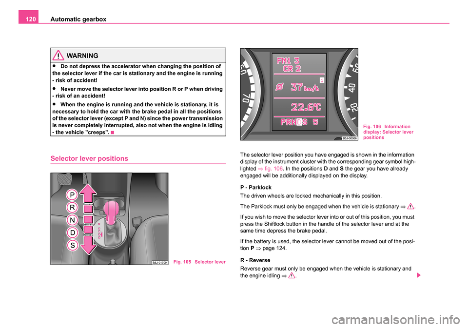
Selector lever positionsThe selector lever position you have engaged is shown in the information
display of the instrument cluster with the corresponding gear symbol high-
lighted ⇒fig. 106 . In the positions D and S the gear you have already
engaged will be additionally displayed on the display.
P - Parklock
The driven wheels are locked mechanically in this position.
The Parklock must only be engaged when the vehicle is stationary ⇒.
If you wish to move the selector lever into or out of this position, you must
press the Shiftlock button in the handle of the selector lever and at the
same time depress the brake pedal.
If the battery is used, the selector lever cannot be moved out of the posi-
tion P ⇒ page 124.
R - Reverse
Reverse gear must only be engaged when the vehicle is stationary and
the engine idling ⇒.
Fig. 105 Selector lever
Fig. 106 Information
display: Selector lever
positions
NKO 20 A05.book Page 120 Wednesday, June 21, 2006 1:42 PM