Page 241 of 298

If and when239
Safety First
Operating instructions
Tips and Maintenance
Te c h n i c a l D a t a
Removing and fitting the wheel
For removal and fitting the wheel, the following tasks must be
completed.Change the wheel as described below after loosening the wheel
bolts and raising the vehicle with the jack.
Removing a wheel
– Unscrew the bolts using the hexagonal tool in the handle of the
screwdriver (vehicle tool) and place them on a clean surface
⇒ fig. 176 .
Fitting a wheel
– Screw in the wheel bolts and tighten them lightly using the hexagonal socket in the screwdriver handle.
The wheel bolts should be clean and turn easily. Before fitting the spare
wheel, inspect the condition of the wheel and hub mounting surfaces. These
surfaces must be clean before fitting the wheel.
The hexagonal socket in the screwdriver handle makes it easier to turn the
wheel bolts when they are loose. The reversible screwdriver blade should be
removed when the tool is used for this purpose.
If tyres with a specific direction of ro tation are fitted, note the direction of
rotation.
Note
Do not use the hexagonal socket in the screwdriver handle to loosen or
tighten the wheel bolts.Anti-theft wheel bolts
A special adapter is required to turn the anti-theft wheel
bolts.
Fig. 176 Wheel change:
Hexagon socket in screw-
driver handle to turn the
wheel bolts after they
have been loosened
Fig. 177 Anti-theft wheel
bolt
toledo_angles_0706 Seite 239 Dienstag, 5. September 2006 10:32 10
Page 242 of 298

If and when
240
– Insert the adapter onto the wheel bolt and push it on as far as it will go ⇒page 239, fig. 177 .
– Fit the box spanner as far as it will go over the adapter.
– Loosen or tighten the wheel bolt as appropriate.Code number
The code number of the anti-theft wheel bolt is stamped on the front of the
adapter.
The code number should be noted and kept in a safe place, as it is only by
using the code number that a duplicate adapter can be obtained from an
Authorised Service Centre.Tyres with directional tread pattern
Tyres with directional tread pattern must be fitted so that they
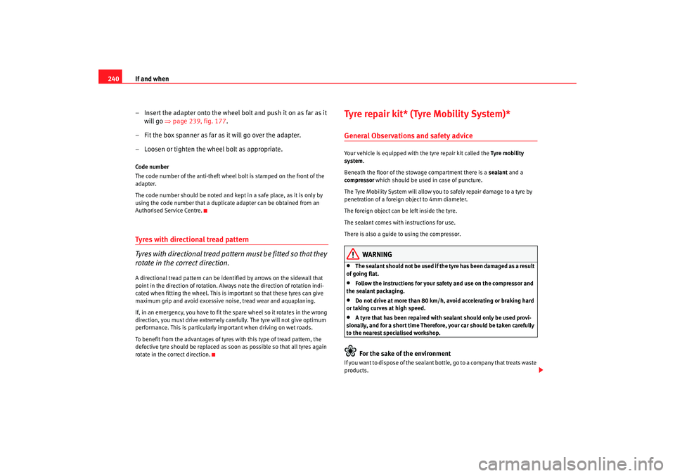
rotate in the correct direction.A directional tread pattern can be identified by arrows on the sidewall that
point in the direction of rotation. Always note the direction of rotation indi-
cated when fitting the wheel. This is important so that these tyres can give
maximum grip and avoid excessive noise, tread wear and aquaplaning.
If, in an emergency, you have to fit the spare wheel so it rotates in the wrong
direction, you must drive extremely ca refully. The tyre will not give optimum
performance. This is particularly important when driving on wet roads.
To benefit from the advantages of tyres with this type of tread pattern, the
defective tyre should be replaced as soon as possible so that all tyres again
rotate in the correct direction.
Tyre repair kit* (Tyre Mobility System)*General Observations and safety adviceYour vehicle is equipped with the tyre repair kit called the Tyre mobility
system.
Beneath the floor of the stowage compartment there is a sealant and a
compressor which should be used in case of puncture.
The Tyre Mobility System will allow you to safely repair damage to a tyre by
penetration of a foreign object to 4mm diameter.
The foreign object can be left inside the tyre.
The sealant comes with instructions for use.
There is also a guide to using the compressor.
WARNING
•
The sealant should not be used if th e tyre has been damaged as a result
of going flat.
•
Follow the instructions for your safety and use on the compressor and
the sealant packaging.
•
Do not drive at more than 80 km/h, avo id accelerating or braking hard
or taking curves at high speed.
•
A tyre that has been repaired with sealant should only be used provi-
sionally, and for a short time Therefore, your car should be taken carefully
to the nearest spec ialised workshop.For the sake of the environment
If you want to dispose of the sealant bottle, go to a company that treats waste
products.
toledo_angles_0706 Seite 240 Dienstag, 5. September 2006 10:32 10
Page 243 of 298

If and when241
Safety First
Operating instructions
Tips and Maintenance
Te c h n i c a l D a t a
Note
Seek professional assistance if the repair of a tyre puncture is not possible
with the sealing compound.Preparation work
What you must do before changing a wheel.– If you have a flat tyre or puncture, park the vehicle as far away
from the flow of traffic as possible.
–Apply the handbrake firmly.
–Engage the first gear, or put the selector lever to position P for
those vehicles with an automatic gearbox.
– All passengers must leave the vehicle. They should wait in a safe
area (for instance behind the roadside crash barrier).
– Check whether the puncture can be mended using the Tyre Mobility System “General observations and safety advice”.
– Unscrew cap from the valve of the affected wheel.
–Take the tyre repair kit from the luggage compartment.
WARNING
Put the hazard warning lights on and place the warning triangle in position.
This is for your own safety and also warns other road users.
Caution
Take the utmost caution when repairing a flat tyre on a gradient.
Note
Please observe legal requirements when doing so.Repairing the puncture
To repair the puncture, once the preliminary tasks are done,
follow these steps.Apply the sealant
– The instructions for using the sealant correctly are on the pack-
aging.
Inflate the tyres.
– Remove the compressor and hose.
– Tighten the fastening nut onto the tyre valve.
– Connect the compressor power supply to the 12 Volt socket.
– Connect the compressor and chec k the tyre pressure with the
pressure gauge.
Finish the repair
– Remove the compressor hose from the valve.
– Check the cap on the tyre valve.
– Disconnect the compressor from the vehicle mains.
toledo_angles_0706 Seite 241 Dienstag, 5. September 2006 10:32 10
Page 244 of 298
If and when
242
– Put the tools back in the luggage compartment.NoteThe compressor should not operate more than 6 minutesFusesChanging a fuse
If a fuse has blown it must be replaced
Fuse cover underneath the steering wheel
– Switch off the ignition and the component concerned.
– Identify the fuse for the failed component ⇒page 244.
– Take the plastic clip from inside the fuse cover, fit it onto the blown fuse and pull the fuse out.
– Replace the blown fuse (which will have a melted metal strip) with a new fuse of the same ampere rating.
Fuse cover in engine compartment
– Switch off the ignition and the component concerned.
– Prise off the fuse cover in the engine compartment by pressing the tabs towards the centre of the cover ⇒fig. 179 .
– Identify the fuse for the failed component ⇒page 244.
Fig. 178 Left side of dash
panel: Fuse box cover
Fig. 179 Fuse box cover
in engine compartment
toledo_angles_0706 Seite 242 Dienstag, 5. September 2006 10:32 10
Page 245 of 298

If and when243
Safety First
Operating instructions
Tips and Maintenance
Te c h n i c a l D a t a
– Take the plastic clip from inside the fuse cover (at left-hand end
of the dash panel), fit it onto the blown fuse and pull the fuse out.
– Replace the blown fuse (which will have a melted metal strip) with a new fuse of the same ampere rating.
– Carefully fit the fuse cover back on to ensure no water can enter the fuse box.The individual electrical circuits are pr otected by fuses. The fuses are located
behind a cover at the left-hand end of the dash panel and on the left-hand
side of the engine compartment.
The electric windows are protected by circuit breakers. These reset automat-
ically after a few seconds when the overload (caused for example by frozen
windows) has been corrected.
Colour coding of fuses
WARNING
Never “repair” damaged fuses and never replace them with fuses with a
higher rating. Failure to comply could re sult in fire. This could also cause
damage to other parts of the electrical system.
Note
•
If a newly replaced fuse blows again after a short time, the electrical
system must be checked by a qualified workshop as soon as possible.
•
If you replace a fuse with a stronger fuse, you could cause damage to
another location in the electrical system.
•
Always keep some spare fuses in the vehicle. These are available from
SEAT dealers.
Colour
Amperes
light brown 5
red 10
blue 15
yellow 20
natural (white) 25
green 30
orange 40
red 50
white 80
blue100
grey 150
violet 200
Colour
Amperes
toledo_angles_0706 Seite 243 Dienstag, 5. September 2006 10:32 10
Page 246 of 298
If and when
244Fuses on left side of dash panelFuses
Number Electrical equipment Amperes
1V aca n t
2V aca n t
3V aca n t
4V aca n t
5V aca n t
6V aca n t
7V aca n t
8V aca n t
9 Airbag 5
10 Vacant
11 Vacant
11 After-sales kit 5
12 Left hand side xenon headlight 10
13 Heating controls/ESP, ASR switch/Reverse gear/Telephone pre-installation 5
14 ABS/ESP control unit/ Engine/ Headlights/ Trailer control unit/ light switch/ Instrument panel 10
15 Headlight control unit/ Heated windscreens/ Instrument lighting/ Diagnosis control unit 10
16 Right hand side xenon headlight 10
17 D2L Engine (2.0 litre 147 kW 4 speed TFSI) 10
18 Vacant
19 Vacant
20 Park Pilot (Parking aid) / Gear selector lever/ ESP control unit 10
toledo_angles_0706 Seite 244 Dienstag, 5. September 2006 10:32 10
Page 247 of 298
If and when245
Safety First
Operating instructions
Tips and Maintenance
Te c h n i c a l D a t a
21
Cable control unit 7,5
22 Volumetric alarm sensor/alarm siren 5
23 Diagnosis/Rain sensor/Light switch 10
24 Vacant
25 Automatic gearbox control unit connection 20
26 Vacuum pump 20
27 Vacant
28 Windscreen wiper motor/Cable control unit 20
29 Vacant
30 Cigarette lighter / socket 20
31 Vacant
32 Vacant
33 Heater 40
34 Vacant
35 Vacant
36 2.0 litre 147 kW engine 10
37 2.0 litre 147 kW engine 10
38 2.0 litre 147 kW engine 10
39 Trailer control unit (coupling) 15
40 Trailer control unit (indicators, brakes and left side) 20
41 Trailer control unit (fog light, reversing light and right side) 20
42 Towing kit 15
43 Vacant
44 Rear window heater 25
Number
Electrical equipment Amperes
toledo_angles_0706 Seite 245 Dienstag, 5. September 2006 10:32 10
Page 248 of 298
If and when
246Some of the electrical items listed in the table are only fitted on certain
models or are optional extras.
Please note that the above list, while corr ect at the time of printing, is subject
to alterations. If discrepancies should occur, please refer to the sticker on the
inside of the fuse cover for the correct information for your model. 45
Front electric windows 30
46 Rear electric windows 30
47 Engine (gauge, fuel relay) 15
48 Convenience controls 20
49 Heating controls 40
50 Heated seats 30
51 Sunroof 20
52 Headlight washer system 20
53 Towing kit 20
54 Taxi (taxi metre power supply) 5
55 Towing kit 20
56 Taxi (transmitter power supply) 15
57 Vacant
58 Central locking control unit 30
Number
Electrical equipment Amperes
toledo_angles_0706 Seite 246 Dienstag, 5. September 2006 10:32 10