2006 PORSCHE BOXSTER ESP
[x] Cancel search: ESPPage 134 of 296

134
Controls, Instruments
Setting temperaturefPress button H upwards or downwards
respectively.
To suit personal comfort, the interior temperature
can be adjusted between 61°F and 85°F/16°C
and 29.5°C.
Recommendation: 72°F/22 °C.
If “LO” or “HI” appears on the display, the system
is operating at maximum cooling or heating
power.
Automatic control is no longer active.
Note
If the preselected temperature is changed, the
blower speed can increase automatically in
automatic mode.
The desired temperature is reached more quickly
this way.
Sensors
To avoid affecting the performance of the air-
conditioning system:
fDo not cover the sun sensor on the instrument
panel or the temperature sensor D.
Defrost windshieldfPress button B (switch on or off).
The windshield is demisted or defrosted as
quickly as possible.
Air flows to the windshield only.
The light-emitting diode in the button lights up.ECO – switching the air-conditioning
compressor on and offThe air conditioning compressor switches off
automatically at temperatures below approx.
37°F/3°C and cannot be switched on, even
manually.
Whenever outside temperatures exceed approx.
37°F/3°C, the air-conditioning compressor is
always switched on in automatic mode.
The compressor can be switched off manually to
save fuel, but control comfort is then limited:
fPress ECO button E.
The compressor is switched off.
The light-emitting diode in the button lights up.
fIf the interior temperature is too high, switch
compressor back on or press AUTO button.
To dry incoming air in damp weather, do not
switch off the air-conditioning compressor.
This prevents misting of windows.
Adjusting blower speedfPress button M upwards or downwards
respectively.
The preset blower speed is increased or
decreased.
The speeds are indicated by a bar display.
The compressor is switched off at low blower
speeds.
If the button is pressed downwards at the lowest
blower stage, the blower and automatic control
are switched off. “OFF” will appear on the display
field.
Pressing the button upwards or pressing the
AUTO button switches the blower and automatic
control back on again.Circulating-air mode
Warning!
Risk of accident due to hampered vision.
In circulating-air mode, the windows may
mist up.
fOnly select circulating-air mode for short
periods.
fIf the windows mist up, switch air-circulation
mode by pressing the air-circulation button
again and selecting the “Defrost windshield” function.
Page 144 of 296

144
Controls, Instruments
Cupholder(holder for drinks cans and cups)
fKeep the cupholder closed while driving.
Warning!
Risk of scalding or damage due to spilling
drinks.
fOnly use containers which fit.
fNever put overfull containers in the cupholder.
fNever use hot drinks.
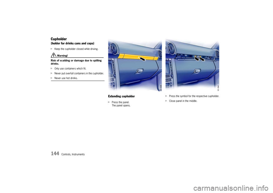
Extending cupholderfPress the panel.
The panel opens.fPress the symbol for the respective cupholder.
fClose panel in the middle.
Page 150 of 296

150
Controls, Instruments
A - Opening front luggage compartment lid
B - Opening rear luggage compartment lid Luggage compartment lidsUnlocking fOperate the appropriate pull-button next to the
driver’s seat.
The luggage compartment is illuminated when
the respective lid is open.
fPlease observe the chapter “LOAD SWITCH-
OFF AFTER 2 HOURS OR 7 DAYS” on Page
246.The luggage compartment lid can also be un-
locked with the radio remote control.
fPlease observe the chapter “KEYS” on Page
17.
Important Note
If the vehicle battery is discharged, the front lug-
gage compartment lid can be opened only by con-
necting an external electrical power source.
fPlease observe the chapter “ELECTRICAL SYS-
TEM” on Page 246.
or the description inside the fuse box lid.
A warning message in the on-board computer
comes on if the lids are not completely closed.
fFully close the lid.
Warning message
Page 155 of 296

Controls, Instruments
155
Car Audio Operation/Tips For radio operation see your radio manual
which is included with your on-board
literature.
fPlease observe the chapter “LOAD SWITCH-
OFF AFTER 2 HOURS OR 7 DAYS” on Page
246. FM reception A vehicle is not an ideal place to listen to a radio.
Because the vehicle moves, reception conditions
are constantly changing.
Buildings, terrain, signal distance and noise from
other vehicles are all working against good recep-
tion.
Some conditions affecting FM may appear to be
problems when they are not.
The following characteristics are completely nor-
mal for a given reception area, and they do not in-
dicate any problem with the radio itself.
Note
Electronic accessories should only be installed by
your authorized Porsche dealer.
Equipment which has not been tested and appro-
ved by Porsche may impair radio reception. Fading and drifting
FM range is limited to about 25 miles (40 km), ex-
cept for some high power stations.
If a vehicle is moving away from the desired stati-
on’s transmitter, the signal will tend to fade and/or
drift. This condition is more prevalent with FM than
AM, and is often accompanied by distortion.
Fading and drifting can be minimized to a certain
degree by careful attention to fine tuning or selec-
tion of a stronger signal.
Static and fluttering
When the line-of-sight link between a transmitter
and vehicle is blocked by large buildings or moun-
tains, the radio sound may be accompanied with
static or fluttering because of the characteristic of
FM.
In a similar effect, a fluttering noise is sometimes
heard when driving along a tree-lined road.
This static and fluttering can be reduced by adjus-
ting the tone control for greater bass response un-
til the disturbance has passed. Multipath
Because of the reflecting characteristics of FM, di-
rect and reflected signals may reach the antenna
at the same time (multipath) and cancel each other
out.
As a vehicle moves through these electronic dead
spots, the listener may hear a momentary flutter
or loss of reception.
Station swapping
When two FM stations are close to each other, and
an electronic dead spot, such as static or multi-
path area, interrupts the original signal, someti-
mes the stronger second signal will be selected
automatically until the original one returns.
This swapping can also occur as you drive away
from the selected station and approach another
station of a stronger signal.
Page 158 of 296

158
Controls, Instruments
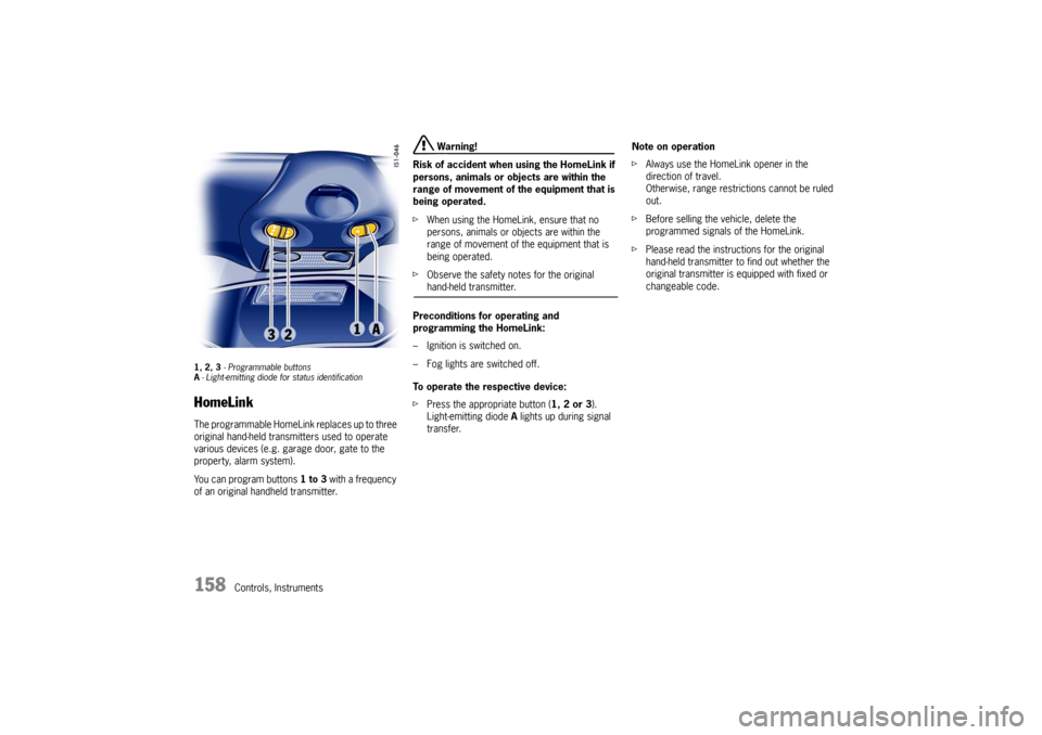
1, 2, 3 - Programmable buttons
A- Light-emitting diode for status identificationHomeLinkThe programmable HomeLink replaces up to three
original hand-held transmitters used to operate
various devices (e.g. garage door, gate to the
property, alarm system).
You can program buttons 1 to 3 with a frequency
of an original handheld transmitter.
Warning!
Risk of accident when using the HomeLink if
persons, animals or objects are within the
range of movement of the equipment that is
being operated.
fWhen using the HomeLink, ensure that no
persons, animals or objects are within the
range of movement of the equipment that is
being operated.
fObserve the safety notes for the original hand-held transmitter.
Preconditions for operating and
programming the HomeLink:
– Ignition is switched on.
– Fog lights are switched off.
To operate the respective device:
fPress the appropriate button (1, 2 or 3).
Light-emitting diode A lights up during signal
transfer.Note on operation
fAlways use the HomeLink opener in the
direction of travel.
Otherwise, range restrictions cannot be ruled
out.
fBefore selling the vehicle, delete the
programmed signals of the HomeLink.
fPlease read the instructions for the original
hand-held transmitter to find out whether the
original transmitter is equipped with fixed or
changeable code.
Page 164 of 296

164
Shifting Gear
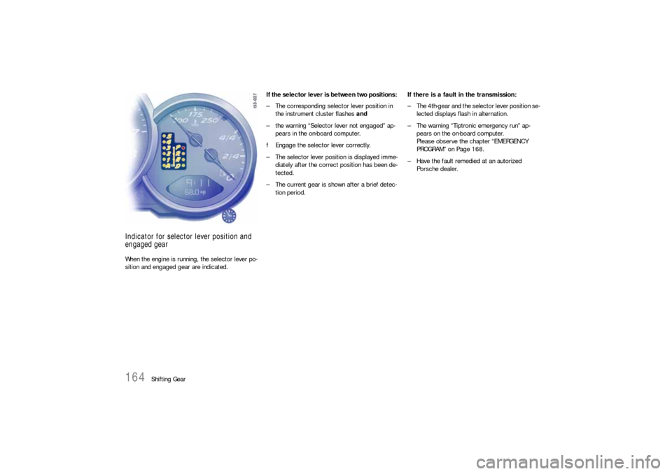
Indicator for selector lever position and
engaged gear When the engine is running, the selector lever po-
sition and engaged gear are indicated. If the selector lever is between two positions:
– The corresponding selector lever position in
the instrument cluster flashes and
– the warning “Selector lever not engaged” ap-
pears in the on-board computer.
fEngage the selector lever correctly.
– The selector lever position is displayed imme-
diately after the correct position has been de-
tected.
– The current gear is shown after a brief detec-
tion period.If there is a fault in the transmission:
– The 4th-gear and the selector lever position se-
lected displays flash in alternation.
– The warning “Tiptronic emergency run” ap-
pears on the on-board computer.
Please observe the chapter “EMERGENCY
PROGRAM” on Page 168.
– Have the fault remedied at an autorized
Porsche dealer.
Page 166 of 296

166
Shifting Gear Shifting gear on the steering wheel
With the toggle switches on the steering wheel,
you can change temporarily from automatic
selection mode D to manual mode M.
Advantages:
– Shifting down before bends and on entering bu-
ilt-up areas.
– Shifting down on downward slopes (engine bra-
king).
– Shifting down for brief spurts of acceleration.
– Selecting 1st gear for moving off.
The manual selection mode remains engaged:
– for cornering (depending on the lateral
acceleration) and overrunning,
– when the vehicle is stationary
(e.g. at a junction).
The system leaves manual selection mode:
– automatically after approx. 8 seconds
(unless cornering or overrunning),
– if you depress the accelerator to kickdown,
– after moving off. Temporary change-down
Conditions:
Speed is higher than approx. 33 mph (54 km/h).
fDepress accelerator quickly.
The Tiptronic changes temporarily to the spor-
tiest gear-changing map, i.e. to the highest
possible gear-changing points. Correspondin-
gly, the transmission shifts down immediately
by one or two gears.
Ending the function:
fRelease the accelerator markedly. Kickdown
The kickdown function is active in selector lever
position D, even if you temporarily change to ma-
nual mode M using the toggle switches on the
steering wheel.
fFor optimum acceleration, e.g. when overta-
king, depress the accelerator pedal beyond
the full-throttle point (kickdown).
The transmission shifts down depending on the
speed of travel and engine speed.
Upward shifts occur at the highest possible engine
speeds.
These gear-changing speeds remain active until
the accelerator is released to approx. 80% of the
wide open throttle position.
Page 175 of 296

Mobile Roofs
175
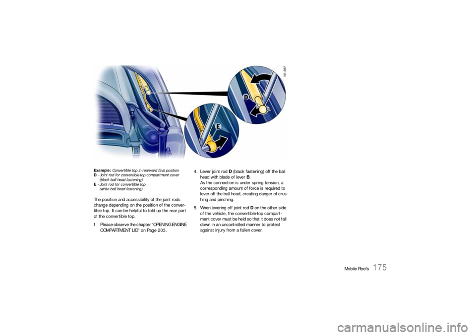
Example: Convertible top in rearward final position
D - Joint rod for convertible-top compartment cover
(black ball head fastening)
E - Joint rod for convertible top
(white ball head fastening) The position and accessibility of the joint rods
change depending on the position of the conver-
tible top. It can be helpful to fold up the rear part
of the convertible top.
fPlease observe the chapter “OPENING ENGINE
COMPARTMENT LID” on Page 203.4. Lever joint rod D (black fastening) off the ball
head with blade of lever B.
As the connection is under spring tension, a
corresponding amount of force is required to
lever off the ball head, creating danger of crus-
hing and pinching.
5. When levering off joint rod D on the other side
of the vehicle, the convertible-top compart-
ment cover must be held so that it does not fall
down in an uncontrolled manner to protect
against injury from a fallen cover.