Page 238 of 281
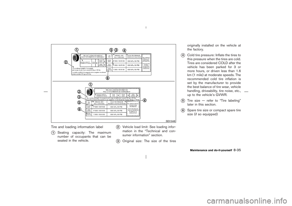
Tire and loading information label�1
Seating capacity: The maximum
number of occupants that can be
seated in the vehicle.
�2
Vehicle load limit: See loading infor-
mation in the “Technical and con-
sumer information” section.
�3
Original size: The size of the tiresoriginally installed on the vehicle at
the factory.
�4
Cold tire pressure: Inflate the tires to
this pressure when the tires are cold.
Tires are considered COLD after the
vehicle has been parked for 3 or
more hours, or driven less than 1.6
km (1 mile) at moderate speeds. The
recommended cold tire inflation is
set by the manufacturer to provide
the best balance of tire wear, vehicle
handling, driveability, tire noise, etc.,
up to the vehicle’s GVWR.
�5
Tire size — refer to “Tire labeling”
later in this section.
�6
Spare tire size or compact spare tire
size (if so equipped)
SDI1948
Maintenance and do-it-yourself
8-35
�
06.4.14/T30-J/V5.0
�
Page 239 of 281

Checking the tire pressure1. Remove the valve stem cap from the
tire.
2. Press the pressure gauge squarely
onto the valve stem. Do not press too
hard or force the valve stem sideways,
or air will escape. If the hissing sound
of air escaping from the tire is heard
while checking the pressure, reposi-
tion the gauge to eliminate this leak-
age.3. Remove the gauge.
4. Read the tire pressure on the gauge
stem and compare it to the specifica-
tion shown on the Tire and Loading
Information label.
5. Add air to the tire as needed. If too
much air is added, press the core of
the valve stem briefly with the tip of the
gauge stem to release pressure. Re-
check the pressure and add or release
air as needed.
6. Install the valve stem cap.
7. Check the pressure of all other tires,
including the spare.
SizeCold Tire
Inflation
Pressure
Front
Original
TireP215/65/R16
P215/60/R17220 kPa,
32 PSI
200 kPa,
29 PSI
Rear
Original
TireP215/65/R16
P215/60/R17240 kPa,
35 PSI
200 kPa,
29 PSI
Spare
TireP215/65/R16
P215/60/R17240 kPa,
35 PSI
200 kPa,
29 PSI
SDI1949
8-36
Maintenance and do-it-yourself
�
06.4.14/T30-J/V5.0
�
Page 241 of 281
 for a
new tire (example: DOT XX XX XXX
XXXX)
1. DOT: Abbreviation for the “Depart-
ment Of Transportation”. The
symbol can be placed above,
below or to the left")
�2
TIN (Tire Identification Number) for a
new tire (example: DOT XX XX XXX
XXXX)
1. DOT: Abbreviation for the “Depart-
ment Of Transportation”. The
symbol can be placed above,
below or to the left or right of the
Tire Identification Number.
2. Two-digit code: Manufacturer’s identi-
fication mark
3. Two-digit code: Tire size4. Three-digit code: Tire type code (Op-
tional)
5. Three-digit code: Date of Manufacture
6. Four numbers represent the week and
year the tire was built. For example, the
numbers 3103 means the 31st week
of 2003. If these numbers are missing,
then look on the other sidewall of the
tire.
�3
Tire ply composition and material
The number of layers or plies of
rubber-coated fabric in the tire. Tire
manufacturers also must indicate the
materials in the tire, which include
steel, nylon, polyester, and others.
�4
Maximum permissible inflation pres-
sure
This number is the greatest amount
of air pressure that should be put in
the tire. Do not exceed the maximum
permissible inflation pressure.
�5
Maximum load rating
This number indicates the maximumload in kilograms and pounds that
can be carried by the tire. When
replacing the tires on the vehicle,
always use a tire that has the same
load rating as the factory installed
tire.
�6
Term of “tubeless” or “tube type”
Indicates whether the tire requires an
inner tube (“tube type”) or not
(“tubeless”).
�7
The word “radial”
The word “radial” is shown if the tire
has radial structure.
�8
Manufacturer or brand name
Manufacturer or brand name is
shown.
Other tire-related terminology:
In addition to the many terms that are
defined throughout this section, Intended
Outboard Sidewall is (1) the sidewall that
contains a whitewall, bears white letter-
ing or bears manufacturer, brand and/or
model name molding that is higher or
deeper than the same molding on the
SDI1607
EXAMPLE
8-38
Maintenance and do-it-yourself
�
06.4.14/T30-J/V5.0
�
Page 243 of 281

between tires on the front and rear
axles which will cause excessive tire
wear and may damage the transmis-
sion, transfer case and differential
gears.
�ONLY use spare tires specified for
each 4-wheel drive model.
If excessive tire wear is found, it is recommended
that all four tires be replaced with tires of the
same size, brand, construction and tread pat-
tern. The tire pressure and wheel alignment
should also be checked and corrected as nec-
essary. Contact a NISSAN dealer.
Tire chains must be installed only on the
front wheels and not on the rear wheels.
Do not drive with tire chains on paved roads
which are clear of snow. Driving with chains in
such conditions can cause damage to the vari-
ous mechanisms of the vehicle due to some
overstress.
TIRE CHAINSUse of tire chains may be prohibited according
to location. Check the local laws before installing
tire chains. When installing tire chains, make
sure they are of proper size for the tires on yourvehicle and are installed according to the chain
manufacturer’s suggestions.Use only SAE
class S chains.Class “S” chains are used on
vehicles with restricted tire to vehicle clearance.
Vehicles that can use Class “S” chains are
designed to meet the SAE standard minimum
clearances between the tire and the closest
vehicle suspension or body component required
to accommodate the use of a winter traction
device (tire chains or cables). The minimum
clearances are determined using the factory
equipped tire size. Other types may damage
your vehicle. Use chain tensioners when recom-
mended by the tire chain manufacturer to ensure
a tight fit. Loose end links of the tire chain must
be secured or removed to prevent the possibility
of whipping action damage to the fenders or
undercarriage. If possible, avoid fully loading
your vehicle when using tire chains. In addition,
drive at a reduced speed. Otherwise, your ve-
hicle may be damaged and/or vehicle handling
and performance may be adversely affected.
�Do not use the chains on dry roads.
Tire chains must be installed only on the
front wheels and not on the rear wheels.
Do not drive with tire chains on paved roads
which are clear of snow. Driving with chains in
such conditions can cause damage to the vari-
ous mechanisms of the vehicle due to someoverstress.8-40
Maintenance and do-it-yourself
�
06.4.14/T30-J/V5.0
�
Page 244 of 281
.
See “Flat tire” in the “6. In case of
emergency” section of this manual for tire
repl")
CHANGING WHEELS AND TIRES
Tire rotationNISSAN recommends rotating the tires
every 12,000 km (7,500 miles).
See “Flat tire” in the “6. In case of
emergency” section of this manual for tire
replacing procedures.
As soon as possible, tighten the
wheel nuts to the specified torque
with a torque wrench.Wheel nut tightening torque:
108 N⋅m (11 kg-m, 80 ft-lb)
The wheel nuts must be kept tight-
ened to specifications at all times. It
is recommended that wheel nuts be
tightened to the specification at
each tire rotation interval.
WARNING
�After rotating the tires, check
and adjust the tire pressure.
�Retighten the wheel nuts when
the vehicle has been driven for
1,000 km (600 miles) (also in
cases of a flat tire, etc.).
�Do not include the spare tire in
the tire rotation.
�For additional information re-
garding tires, refer to “Tire
Safety Information” in the War-
ranty Information Booklet.1. Wear indicator
2. Location mark
Tire wear and damage
WARNING
�Tires should be periodically in-
spected for wear, cracking,
bulging or objects caught in the
tread. If excessive wear, cracks,
bulging or deep cuts are found,
SDI1662
MDI0004A
Maintenance and do-it-yourself
8-41
�
06.4.14/T30-J/V5.0
�
Page 246 of 281
get out of balance. Therefore, they should be
balanced as required.
Wheel balance service should be per-
formed with the wheels off the vehicle.
Spin balancing the wheels on the vehicle
could lead to mechanical damage.
For additional information regarding tires, refer to
“Tire Safety Information” in the Warranty Infor-
mation Booklet.Care of wheels�Wash the wheels when washing the vehicle
to maintain their appearance.
�Clean the inner side of the wheels when the
wheel is changed or the underside of the
vehicle is washed.
�Do not use abrasive cleaners when washing
the wheels.
�Inspect wheel rims regularly for dents or
corrosion. Such damage may cause loss of
pressure or poor seal at the tire bead.
�NISSAN recommends waxing the road wheel
sidewalls to protect against road salt in areas
where it is used during winter.
Maintenance and do-it-yourself
8-43
�
06.4.14/T30-J/V5.0
�
Page 255 of 281
WHEELS AND TIRES
Road wheelType Size Offset mm (in)
Steel 16 x 6-1/2JJ 40 (1.57)
Aluminum16 x 6-1/2JJ 40 (1.57)
17 x 6-1/2JJ 40 (1.57)TireType Size Pressure (COLD)
ConventionalP215/65R16 220 kPa (32 psi)
P215/60R17 200 kPa (29 psi)
Spare Conventional —
DIMENSIONS AND WEIGHTSOverall length mm (in) 4,455 (175.4)
Overall width mm (in) 1,765 (69.5)
Overall heightmm (in) 1,675 (65.9)
mm (in) 1,750 (68.9)*
Front tread mm (in) 1,530 (60.2)
Rear tread mm (in) 1,530 (60.2)
Wheelbase mm (in) 2,625 (103.3)
Gross vehicle weight rating kg (lb)
See the C.M.V.S.S. certifica-
tion label on the driver’s side
lock pillar. Gross axle weight rating
Front kg (lb)
Rear kg (lb)
*: Rear air spoiler or roof rail with driving lights equipped model
9-8
Technical and consumer information
�
06.4.14/T30-J/V5.0
�
Page 258 of 281
TIRE AND LOADING INFORMATION
LABELThe cold tire pressure are shown on the Tire and
Loading Information label affixed to the driver’s
door center pillar.
AIR CONDITIONER SPECIFICATION
LABELThe air conditioner specification label is affixed
inside of the hood as shown.
WARNING
�It is extremely dangerous to
ride in a cargo area inside of a
vehicle. In a collision, people
riding in these areas are more
likely to be seriously injured or
killed
�Do not allow people to ride in
any area of your vehicle that is
not equipped with seats and
seat belts.
�Be sure everyone in your ve-
hicle is in a seat and using a
seat belt properly.TERMSIt is important to familiarize yourself with
the following terms before loading your
vehicle:
�CurbWeight (actual weight of your
vehicle) - vehicle weight including:
standard and optional equipment, flu-
STI0394
STI0395
VEHICLE LOADING
INFORMATIONTechnical and consumer information
9-11
�
06.4.14/T30-J/V5.0
�


Steel 16 x 6-1/2JJ 40 (1.57)
Aluminum16 x 6-1/2JJ 40 (1.57)
17 x 6-1/2JJ 40 (1.57)TireType Size Pressure (COLD)
ConventionalP215/65R16 220 kPa (32 p")
