Page 1712 of 2896

DTC P2A00 A/F SENSOR 1
EC-543
C
D
E
F
G
H
I
J
K
L
MA
EC
Revision: June 20062007 Versa
Specification data are reference values and are measured between each terminal and ground.
Pulse signal is measured by CONSULT-II.
CAUTION:
Do not use ECM ground terminals when measuring input/output voltage. Doing so may result in dam-
age to the ECM's transistor. Use a ground other than ECM terminals, such as the ground.
: Average voltage for pulse signal (Actual pulse signal can be confirmed by oscilloscope.)
Diagnostic ProcedureUBS00QNU
1. CHECK GROUND CONNECTIONS
1. Turn ignition switch OFF.
2. Loosen and retighten ground screws on the body.
Refer to EC-150, "
Ground Inspection" .
OK or NG
OK >> GO TO 2.
NG >> Repair or replace ground connections.
TERMI-
NAL
NO.WIRE
COLORITEM CONDITION DATA (DC Voltage)
3 G A/F sensor 1 heater[Engine is running]
�Warm-up condition
�Idle speed
(More than 140 seconds after starting
engine)Approximately 2.9 - 8.8V
49 W A/F sensor 1[Engine is running]
�Warm-up condition
�Engine speed: 2,000 rpmApproximately 1.8V
Output voltage varies with air fuel
ratio.
53 B A/F sensor 1[Ignition switch: ON]Approximately 2.2V
PBIA8148J
:Vehicle front
1. Body ground E24 2. Engine ground F9 3. Engine ground F16
4. Body ground E15
BBIA0698E
Page 1713 of 2896
EC-544Revision: June 2006
DTC P2A00 A/F SENSOR 1
2007 Versa
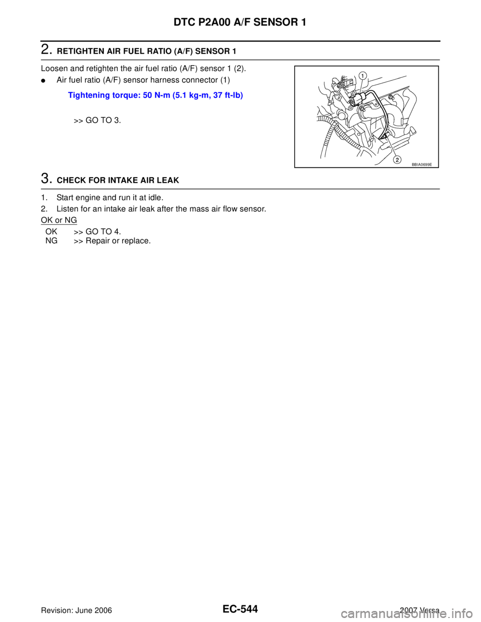
2. RETIGHTEN AIR FUEL RATIO (A/F) SENSOR 1
Loosen and retighten the air fuel ratio (A/F) sensor 1 (2).
�Air fuel ratio (A/F) sensor harness connector (1)
>> GO TO 3.
3. CHECK FOR INTAKE AIR LEAK
1. Start engine and run it at idle.
2. Listen for an intake air leak after the mass air flow sensor.
OK or NG
OK >> GO TO 4.
NG >> Repair or replace.Tightening torque: 50 N-m (5.1 kg-m, 37 ft-lb)
BBIA0699E
Page 1714 of 2896

DTC P2A00 A/F SENSOR 1
EC-545
C
D
E
F
G
H
I
J
K
L
MA
EC
Revision: June 20062007 Versa
4. CLEAR THE SELF-LEARNING DATA.
With CONSULT-II
1. Start engine and warm it up to normal operating temperature.
2. Select “SELF-LEARNING CONT” in “WORK SUPPORT” mode with CONSULT-II.
3. Clear the self-learning control coefficient by touching “CLEAR”.
4. Run engine for at least 10 minutes at idle speed.
Is the 1st trip DTC P0171 and P0172 detected?
Is it difficult to start engine?
Without CONSULT-II
1. Start engine and warm it up to normal operating temperature.
2. Turn ignition switch OFF.
3. Disconnect mass air flow sensor (1) harness connector.
4. Restart engine and let it idle for at least 5 seconds.
5. Stop engine and reconnect mass air flow sensor harness con-
nector.
6. Make sure DTC P0102 is displayed.
7. Erase the DTC memory. Refer to EC-60, "
HOW TO ERASE
EMISSION-RELATED DIAGNOSTIC INFORMATION" .
8. Make sure DTC P0000 is displayed.
9. Run engine for at least 10 minutes at idle speed.
Is the 1st trip DTC P0171 and P0172 detected?
Is it difficult to start engine?
Ye s o r N o
Yes >> Perform trouble diagnosis for DTC P0171 or P0172. Refer to EC-276, "DTC P0171 FUEL INJEC-
TION SYSTEM FUNCTION" or EC-284, "DTC P0172 FUEL INJECTION SYSTEM FUNCTION" .
No >> GO TO 5.
5. CHECK HARNESS CONNECTOR
1. Turn ignition switch OFF.
2. Disconnect A/F sensor 1 harness connector (1).
–Air fuel ratio (A/F) sensor (2)
3. Check harness connector for water.
OK or NG
OK >> GO TO 6.
NG >> Repair or replace harness connector.
PBIB2035E
BBIA0701E
Water should no exist.
BBIA0699E
Page 1736 of 2896
FUEL INJECTOR
EC-567
C
D
E
F
G
H
I
J
K
L
MA
EC
Revision: June 20062007 Versa
2. CHECK OVERALL FUNCTION
With CONSULT-II
1. Start engine.
2. Perform “POWER BALANCE” in “ACTIVE TEST” mode with
CONSULT-II.
3. Make sure that each circuit produces a momentary engine
speed drop.
Without CONSULT-II
1. Start engine.
2. Listen to each fuel injector operating sound.
OK or NG
OK >>INSPECTION END
NG >> GO TO 3.
PBIB0133E
Clicking noise should be heard.
PBIB3332E
Page 1741 of 2896

EC-572Revision: June 2006
FUEL PUMP
2007 Versa
Specification data are reference values and are measured between each terminal and ground.
CAUTION:
Do not use ECM ground terminals when measuring input/output voltage. Doing so may result in dam-
age to the ECM's transistor. Use a ground other than ECM terminals, such as the ground.
Diagnostic ProcedureUBS00PTX
1. CHECK OVERALL FUNCTION
1. Turn ignition switch ON.
2. Pinch fuel feed hose (1) with two fingers.
–Illustration shows the view with intake air duct removed.
OK or NG
OK >>INSPECTION END
NG >> GO TO 2.
2. CHECK FUEL PUMP POWER SUPPLY CIRCUIT-I
1. Turn ignition switch OFF.
2. Disconnect ECM harness connector.
3. Turn ignition switch ON.
4. Check voltage between ECM terminal 23 and ground with CON-
SULT-II or tester.
OK or NG
OK >> GO TO 5.
NG >> GO TO 3.
TERMI-
NAL
NO.WIRE
COLORITEM CONDITION DATA (DC Voltage)
23 GR Fuel pump relay[Ignition switch: ON]
�For 1 second after turning ignition switch ON
[Engine is running]0 - 1.0V
[Ignition switch: ON]
�More than 1 second after turning ignition
switch ONBATTERY VOLTAGE
(11 - 14V)
Fuel pressure pulsation should be felt on the fuel
feed hose for 1 second after ignition switch is turned
ON.
BBIA0712E
Voltage: Battery voltage
PBIA9573J
Page 1749 of 2896

EC-580Revision: June 2006
IGNITION SIGNAL
2007 Versa
Specification data are reference values and are measured between each terminal and ground.
Pulse signal is measured by CONSULT-II.
CAUTION:
Do not use ECM ground terminals when measuring input/output voltage. Doing so may result in dam-
age to the ECM's transistor. Use a ground other than ECM terminals, such as the ground.
: Average voltage for pulse signal (Actual pulse signal can be confirmed by oscilloscope.)
Diagnostic ProcedureUBS00PU2
1. CHECK ENGINE START
Turn ignition switch OFF, and restart engine.
Is engine running?
Ye s o r N o
Yes (With CONSULT-II)>>GO TO 2.
Yes (Without CONSULT-II)>>GO TO 3.
No >> GO TO 4.
2. CHECK OVERALL FUNCTION
With CONSULT-II
1. Perform “POWER BALANCE” in “ACTIVE TEST” mode with
CONSULT-II.
2. Make sure that each circuit produces a momentary engine
speed drop.
OK or NG
OK >>INSPECTION END
NG >> GO TO 10.
TER-
MINAL
NO.WIRE
COLORITEM CONDITION DATA (DC Voltage)
17
18
21
22R
LG
G
SBIgnition signal No. 1
Ignition signal No. 2
Ignition signal No. 4
Ignition signal No. 3[Engine is running]
�Warm-up condition
�Idle speed
NOTE:
The pulse cycle changes depending on rpm
at idle0 - 0.3V
[Engine is running]
�Warm-up condition
�Engine speed: 2,500 rpm0.2 - 0.5V
PBIA9265J
PBIA9266J
PBIB0133E
Page 1750 of 2896
IGNITION SIGNAL
EC-581
C
D
E
F
G
H
I
J
K
L
MA
EC
Revision: June 20062007 Versa
3. CHECK OVERALL FUNCTION
Without CONSULT-II
1. Let engine idle.
2. Read the voltage signal between ECM terminals 17, 18, 21, 22
and ground with an oscilloscope.
3. Verify that the oscilloscope screen shows the signal wave as
shown below.
NOTE:
The pulse cycle changes depending on rpm at idle.
OK or NG
OK >>INSPECTION END
NG >> GO TO 10.
4. CHECK IGNITION COIL POWER SUPPLY CIRCUIT-I
1. Turn ignition switch OFF, wait at least 10 seconds and then turn ON.
2. Check voltage between ECM terminal 105 and ground with
CONSULT-II or tester.
OK or NG
OK >> GO TO 5.
NG >> Go to EC-144, "
POWER SUPPLY AND GROUND CIR-
CUIT" .
PBIA9567J
PBIA9265J
Voltage: Battery voltage
PBIA9575J
Page 1754 of 2896
 in IPDM E/R (2) to release fuel pres-
sure.
NOTE:
Do not use CONSULT-II to release fuel pres")
IGNITION SIGNAL
EC-585
C
D
E
F
G
H
I
J
K
L
MA
EC
Revision: June 20062007 Versa
7. Remove fuel pump fuse (1) in IPDM E/R (2) to release fuel pres-
sure.
NOTE:
Do not use CONSULT-II to release fuel pressure, or fuel pres-
sure applies again during the following procedure.
– : Vehicle front
8. Start engine.
9. After engine stalls, crank it two or three times to release all fuel
pressure.
10. Turn ignition switch OFF.
11. Remove all ignition coil harness connectors to avoid the electri-
cal discharge from the ignition coils.
12. Remove ignition coil and spark plug of the cylinder to be checked.
13. Crank engine for 5 seconds or more to remove combustion gas in the cylinder.
14. Connect spark plug and harness connector to ignition coil.
15. Fix ignition coil using a rope etc. with gap of 13 - 17 mm
between the edge of the spark plug and grounded metal portion
as shown in the figure.
16. Crank engine for about 3 seconds, and check whether spark is
generated between the spark plug and the grounded metal por-
tion.
CAUTION:
�Do not approach to the spark plug and the ignition coil
within 50cm. Be careful not to get an electrical shock
while checking, because the electrical discharge voltage
becomes 20kV or more.
�It might cause to damage the ignition coil if the gap of more than 17 mm is taken.
NOTE:
When the gap is less than 13 mm, the spark might be generated even if the coil is malfunctioning.
17. If NG, replace ignition coil with power transistor.
CONDENSER-2
1. Turn ignition switch OFF.
2. Disconnect condenser-2 harness connector.
3. Check resistance between condenser-2 terminals 1 and 2.
4. If NG, replace condenser-2.
Removal and InstallationUBS00PU4
IGNITION COIL WITH POWER TRANSISTOR
Refer to EM-30, "IGNITION COIL, SPARK PLUG AND ROCKER COVER" . Spark should be generated.
PBIB2958E
PBIB2325E
Resistance: Above 1 MΩ [at 25°C (77°F)]
PBIB0794E