Page 638 of 2896

INTELLIGENT KEY SYSTEM
BL-149
C
D
E
F
G
H
J
K
L
MA
B
BL
Revision: June 20062007 Versa
3. CHECK STOP LAMP SWITCH OPERATION
Check continuity between stop lamp switch terminals 1 and 2.
OK or NG
OK >> GO TO 4.
NG >> Replace stop lamp switch.
4. CHECK STOP LAMP SWITCH CIRCUIT
1. Check continuity between Intelligent Key unit harness connector
(A) M52 terminal 26 and stop lamp switch harness connector (B)
E13 terminal 2.
2. Check continuity between Intelligent Key unit harness connector
M52 terminal 26 and ground.
OK or NG
OK >> Check condition of harness and connector.
NG >> Repair or replace harness.
Stop Lamp Switch Check (With M/T)EIS009D9
1. CHECK STOP LAMP SWITCH INPUT SIGNAL
1. Turn ignition switch OFF.
2. Disconnect Intelligent Key unit connector.
3. Check voltage between Intelligent Key unit harness connector
M52 terminal 26 and ground.
OK or NG
OK >> Stop lamp switch is OK.
NG >> GO TO 2.
Component Terminals Condition Continuity
Stop lam p
switch12Brake pedal depressed Yes
Brake pedal not depressed No
WIIA1256E
26 - 2 : Continuity should exist.
26 - Ground : Continuity should not exist.
WIIA1257E
ConnectorTe r m i n a l s
ConditionVoltage (V)
(Approx.)
(+) (-)
M52 26 GroundBrake pedal
depressedBattery volt-
age
Brake pedal
released0
WIIA1207E
Page 640 of 2896
 CheckEIS009DA
1. CHECK CVT DEVICE (PARK POSITION SWITCH) INPUT SIGNAL
1. T")
INTELLIGENT KEY SYSTEM
BL-151
C
D
E
F
G
H
J
K
L
MA
B
BL
Revision: June 20062007 Versa
Check CVT Device (Park Position Switch) CheckEIS009DA
1. CHECK CVT DEVICE (PARK POSITION SWITCH) INPUT SIGNAL
1. Turn ignition switch OFF.
2. While pressing the ignition knob switch, check voltage between Intelligent Key unit harness connector
M52 terminal 10 and ground.
OK or NG
OK >> Replace Intelligent Key unit. Refer to BL-160, "Removal
and Installation of Intelligent Key Unit" .
NG >> GO TO 2.
2. CHECK CVT DEVICE (PARK POSITION SWITCH)
1. Disconnect CVT device (park position switch) connector.
2. Check continuity between CVT device (park position switch) terminals 6 and 8.
OK or NG
OK >> GO TO 3.
NG >> Replace CVT device (park position switch).
3. CHECK PARK POSITION SWITCH GROUND CIRCUIT
Check continuity between CVT device (park position switch) harness
connector M38 terminal 6 and ground.
OK or NG
OK >> GO TO 4.
NG >> Repair or replace harness.
ConnectorTe r m i n a l s
ConditionVoltage (V)
(Approx.)
(+) (-)
M52 10 GroundSelector lever is in "P" position 0
Other than above Battery voltage
WIIA1258E
Component Terminals Condition Continuity
CVT device
(park position
switch)68Selector lever is in "P" position Yes
Other than above No
WIIA1259E
6 – Ground : Continuity should exist.
WIIA1260E
Page 642 of 2896
INTELLIGENT KEY SYSTEM
BL-153
C
D
E
F
G
H
J
K
L
MA
B
BL
Revision: June 20062007 Versa
“P-SHIFT” Warning Lamp (With CVT) CheckEIS009DB
1. CHECK WARNING LAMP OPERATION
With CONSULT-II
�Check “INDICATOR” in “ACTIVE TEST” mode with CONSULT-
II.
�Select “KNOB ON”.
“P-SHIFT” warning lamp should illuminate.
Without CONSULT-II
1. Turn ignition switch OFF.
2. While monitoring the combination meter warning lamps, turn
ignition switch ON. "P-SHIFT" warning lamp should illuminate
for 1 second to perform a bulb check.
OK or NG
OK >> INSPECTION END
NG >> Check combination meter. Refer to DI-5, "
COMBINATION METERS" .
PIIB4356E
WIIA1262E
Page 643 of 2896
BL-154
INTELLIGENT KEY SYSTEM
Revision: June 20062007 Versa
“LOCK” Warning Lamp (With M/T) CheckEIS009DC
1. CHECK WARNING LAMP OPERATION
With CONSULT-II
�Check “INDICATOR” in “ACTIVE TEST” mode with CONSULT-
II.
�Select “KNOB ON”.
“LOCK” warning lamp should illuminate.
Without CONSULT-II
1. Turn ignition switch OFF.
2. While monitoring the combination meter warning lamps, turn
ignition switch ON. "LOCK" warning lamp should illuminate for 1
second to perform a bulb check.
OK or NG
OK >> INSPECTION END
NG >> Check combination meter. Refer to DI-5, "
COMBINATION METERS" .
PIIB4356E
WIIA1263E
Page 644 of 2896
INTELLIGENT KEY SYSTEM
BL-155
C
D
E
F
G
H
J
K
L
MA
B
BL
Revision: June 20062007 Versa
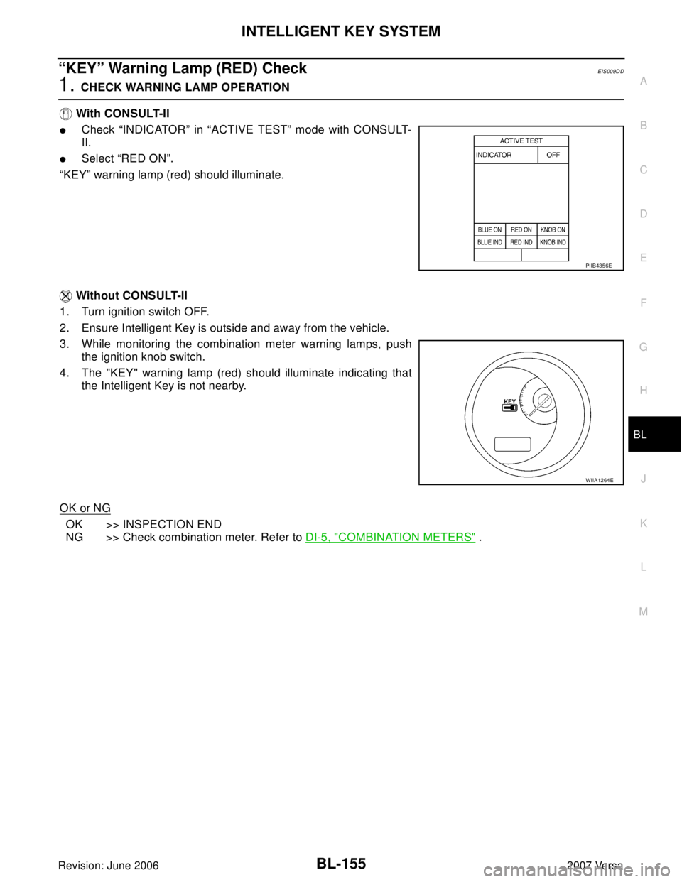
“KEY” Warning Lamp (RED) CheckEIS009DD
1. CHECK WARNING LAMP OPERATION
With CONSULT-II
�Check “INDICATOR” in “ACTIVE TEST” mode with CONSULT-
II.
�Select “RED ON”.
“KEY” warning lamp (red) should illuminate.
Without CONSULT-II
1. Turn ignition switch OFF.
2. Ensure Intelligent Key is outside and away from the vehicle.
3. While monitoring the combination meter warning lamps, push
the ignition knob switch.
4. The "KEY" warning lamp (red) should illuminate indicating that
the Intelligent Key is not nearby.
OK or NG
OK >> INSPECTION END
NG >> Check combination meter. Refer to DI-5, "
COMBINATION METERS" .
PIIB4356E
WIIA1264E
Page 645 of 2896
 CheckEIS009DE
1. CHECK WARNING LAMP OPERATION
With CONSULT-II
�Check “INDICATOR” in “ACTIVE TEST” mo")
BL-156
INTELLIGENT KEY SYSTEM
Revision: June 20062007 Versa
“KEY” Warning Lamp (GREEN) CheckEIS009DE
1. CHECK WARNING LAMP OPERATION
With CONSULT-II
�Check “INDICATOR” in “ACTIVE TEST” mode with CONSULT-
II.
�Select “BLUE ON”.
“KEY” warning lamp (green) should illuminate.
Without CONSULT-II
1. Turn ignition switch OFF.
2. Ensure Intelligent Key is in your possession inside the vehicle.
3. While monitoring the combination meter warning lamps, push
the ignition knob switch.
4. The "KEY" warning lamp (green) should illuminate indicating
that the Intelligent Key is nearby.
OK or NG
OK >> INSPECTION END
NG >> Check combination meter. Refer to DI-5, "
COMBINATION METERS" .
Check Warning Chime in Combination MeterEIS0092R
1. CHECK WARNING CHIME OPERATION
With CONSULT-II
�Check “INSIDE BUZZER” in “ACTIVE TEST” mode with CON-
SULT-II.
�Touch “TAKE OUT”, “KNOB” and “KEY” on “ACTIVE TEST”
screen.
OK or NG
OK >> INSPECTION END
NG >> GO TO 2.
PIIB4356E
WIIA1264E
Does each warning chime sound?
PIIB6619E
Page 647 of 2896
BL-158
INTELLIGENT KEY SYSTEM
Revision: June 20062007 Versa
3. CHECK HORN RERAY CIRCUIT
1. Turn ignition switch OFF.
2. Disconnect IPDM E/R and horn relay connector.
3. Check continuity between IPDM E/R harness connector and
horn relay harness connector.
4. Check continuity between IPDM E/R harness connector and
ground.
OK or NG
OK >> Check condition of harness and connector.
NG >> Repair or replace harness.
Headlamp Function CheckEIS0092U
1. CHECK HEADLAMP OPERATION
Check if headlamps operate by lighting switch.
Do headlamps come on when turning lighting switch ON?
YES >> Headlamp circuit is OK.
NO >> Check headlamp system. Refer to LT- 5 , "
HEADLAMP (FOR USA)" or LT-27, "HEADLAMP (FOR
CANADA) - DAYTIME LIGHT SYSTEM -" .
AB
Continuity
IPDM E/R
connectorTe r m i n a lHorn relay
connectorTe r m i n a l
E46 45 H-1 1 Yes
A
GroundContinuity
IPDM E/R connector Terminal
E46 45 No
WIIA1252E
Page 669 of 2896

BL-180
BACK DOOR LOCK
Revision: June 20062007 Versa
CONSULT-II APPLICATION ITEMS
Data Monitor
* : With Intelligent Key system
** : Without Intelligent Key system
Active Test
Work FlowEIS009DP
1. Check the symptom and customer's requests.
2. Understand the outline of system. Refer to BL-176, "
System Description" .
3. Repair or replace any malfunctioning parts. Refer to BL-180, "
Trouble Diagnosis Chart by Symptom" .
4. Does back door opener operate normally? If Yes, GO TO 5. If No, GO TO 3.
5. INSPECTION END
Trouble Diagnosis Chart by SymptomEIS009DQ
BCM Power Supply and Ground CircuitEIS009DR
Refer to BCS-16, "BCM Power Supply and Ground Circuit Check" .
Monitor item Content
IGN ON SW Indicates [ON/OFF] condition of ignition switch.
KEYLESS TRUNK** This is displayed even when it is not equipped.
I-KEY TRUNK* Momentarily indicates [ON/OFF] condition of back door open signal from back door opener switch.
TRNK OPNR SW** Indicates [ON/OFF] condition of back door open signal from back door opener switch.
VEHICLE SPEED This is displayed even when it is not equipped.
Test item Content
TRUNK/BACK DOORThis test is able to check back door lock assembly (actuator) unlock operation.
Actuator opens back door lock assembly when “OPEN” on CONSULT-II screen is touched.
Symptom Diagnoses/service procedureReference
page
Back door opener does not operate.
(Without Intelligent Key or power windows)1. Check BCM power supply and ground circuit.BCS-16
2. Check back door opener switch circuit.BL-181
3. Check back door lock assembly (actuator) circuit.BL-189
4. Replace BCM.BCS-25
Back door opener does not operate.
(Without Intelligent Key, with power windows)1. Check BCM power supply and ground circuit.BCS-162. Check back door opener switch circuit.BL-184
3. Check back door lock assembly (actuator) circuit.BL-189
4. Replace BCM.BCS-25
Back door opener does not operate.
(With Intelligent Key)1. Check BCM power supply and ground circuit.BCS-16
2.Check Intelligent Key power supply and ground cir-
cuit.BL-123
3. Check back door opener switch circuit.BL-187
4. Check back door lock assembly (actuator) circuit.BL-189
5. Replace BCM.BCS-25