Page 2430 of 2896

MTC-18
OIL
Revision: June 20062007 Versa
OILPFP:KLG00
Maintenance of Oil Quantity in CompressorEJS00579
The oil in the compressor circulates through the system with the refrigerant. Add oil to compressor when
replacing any component or after a large refrigerant leakage occurred. It is important to maintain the specified
amount.
If oil quantity is not maintained properly, the following malfunctions may result:
�Lack of oil: May lead to a seized compressor.
�Excessive oil: Inadequate cooling (thermal exchange interference)
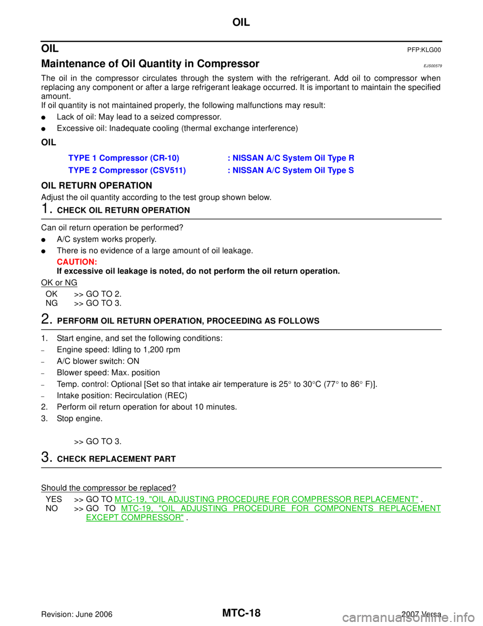
OIL
OIL RETURN OPERATION
Adjust the oil quantity according to the test group shown below.
1. CHECK OIL RETURN OPERATION
Can oil return operation be performed?
�A/C system works properly.
�There is no evidence of a large amount of oil leakage.
CAUTION:
If excessive oil leakage is noted, do not perform the oil return operation.
OK or NG
OK >> GO TO 2.
NG >> GO TO 3.
2. PERFORM OIL RETURN OPERATION, PROCEEDING AS FOLLOWS
1. Start engine, and set the following conditions:
–Engine speed: Idling to 1,200 rpm
–A/C blower switch: ON
–Blower speed: Max. position
–Temp. control: Optional [Set so that intake air temperature is 25° to 30°C (77° to 86° F)].
–Intake position: Recirculation (REC)
2. Perform oil return operation for about 10 minutes.
3. Stop engine.
>> GO TO 3.
3. CHECK REPLACEMENT PART
Should the compressor be replaced?
YES >> GO TO MTC-19, "OIL ADJUSTING PROCEDURE FOR COMPRESSOR REPLACEMENT" .
NO >> GO TO MTC-19, "
OIL ADJUSTING PROCEDURE FOR COMPONENTS REPLACEMENT
EXCEPT COMPRESSOR" . TYPE 1 Compressor (CR-10) : NISSAN A/C System Oil Type R
TYPE 2 Compressor (CSV511) : NISSAN A/C System Oil Type S
Page 2494 of 2896
MTC-82
REFRIGERANT LINES
Revision: June 20062007 Versa
ComponentsEJS0058E
Type 1 A/C System
WJIA2200E
1. Evaporator 2. Expansion valve 3. Low-pressure service valve
4. High-pressure service valve 5. Refrigerant pressure sensor 6. Shaft seal
7. Drain hose
Page 2495 of 2896
REFRIGERANT LINES
MTC-83
C
D
E
F
G
H
I
K
L
MA
B
MTC
Revision: June 20062007 Versa
Type 2 A/C System
WJIA2202E
1. Evaporator 2. Expansion valve 3. Low-pressure service valve
4. High-pressure service valve 5. Refrigerant pressure sensor 6. Shaft seal
7. Drain hose
Page 2496 of 2896
MTC-84
REFRIGERANT LINES
Revision: June 20062007 Versa
Idler Pulley - Without A/C
Refer to MTC-5, "Precautions for Refrigerant Connection" .
Removal and Installation of CompressorEJS0058F
REMOVAL
1. Use the recovery/recycling equipment to evacuate the refrigerant.
2. Remove the two engine undercovers, using power tools.
3. Remove low-pressure flexible hose nut (A) and high-pressure
flexible hose bolt (B) from compressor.
CAUTION:
Cap or wrap the joint of the pipe with suitable material such
as vinyl tape to avoid the entry of air.
NOTE:
Type 1 shown, type 2 is similar.
4. Remove A/C compressor belt. Refer to EM-13, "
DRIVE BELTS"
.
5. Disconnect compressor connector (C).
WJIA2204E
1. Idler pulley 2. Bracket 3. Shaft
SJIA0671E
Page 2497 of 2896

REFRIGERANT LINES
MTC-85
C
D
E
F
G
H
I
K
L
MA
B
MTC
Revision: June 20062007 Versa
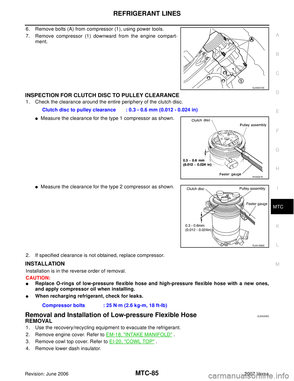
6. Remove bolts (A) from compressor (1), using power tools.
7. Remove compressor (1) downward from the engine compart-
ment.
INSPECTION FOR CLUTCH DISC TO PULLEY CLEARANCE
1. Check the clearance around the entire periphery of the clutch disc.
�Measure the clearance for the type 1 compressor as shown.
�Measure the clearance for the type 2 compressor as shown.
2. If specified clearance is not obtained, replace compressor.
INSTALLATION
Installation is in the reverse order of removal.
CAUTION:
�Replace O-rings of low-pressure flexible hose and high-pressure flexible hose with a new ones,
and apply compressor oil when installing.
�When recharging refrigerant, check for leaks.
Removal and Installation of Low-pressure Flexible HoseEJS0058G
REMOVAL
1. Use the recovery/recycling equipment to evacuate the refrigerant.
2. Remove engine cover. Refer to EM-18, "
INTAKE MANIFOLD" .
3. Remove cowl top cover. Refer to EI-20, "
COWL TOP" .
4. Remove lower dash insulator.
SJIA0672E
Clutch disc to pulley clearance : 0.3 - 0.6 mm (0.012 - 0.024 in)
RHA087E
RJIA1886E
Compressor bolts : 25 N·m (2.6 kg-m, 18 ft-lb)
Page 2508 of 2896

MTC-96
SERVICE DATA AND SPECIFICATIONS (SDS)
Revision: June 20062007 Versa
SERVICE DATA AND SPECIFICATIONS (SDS)PFP:00030
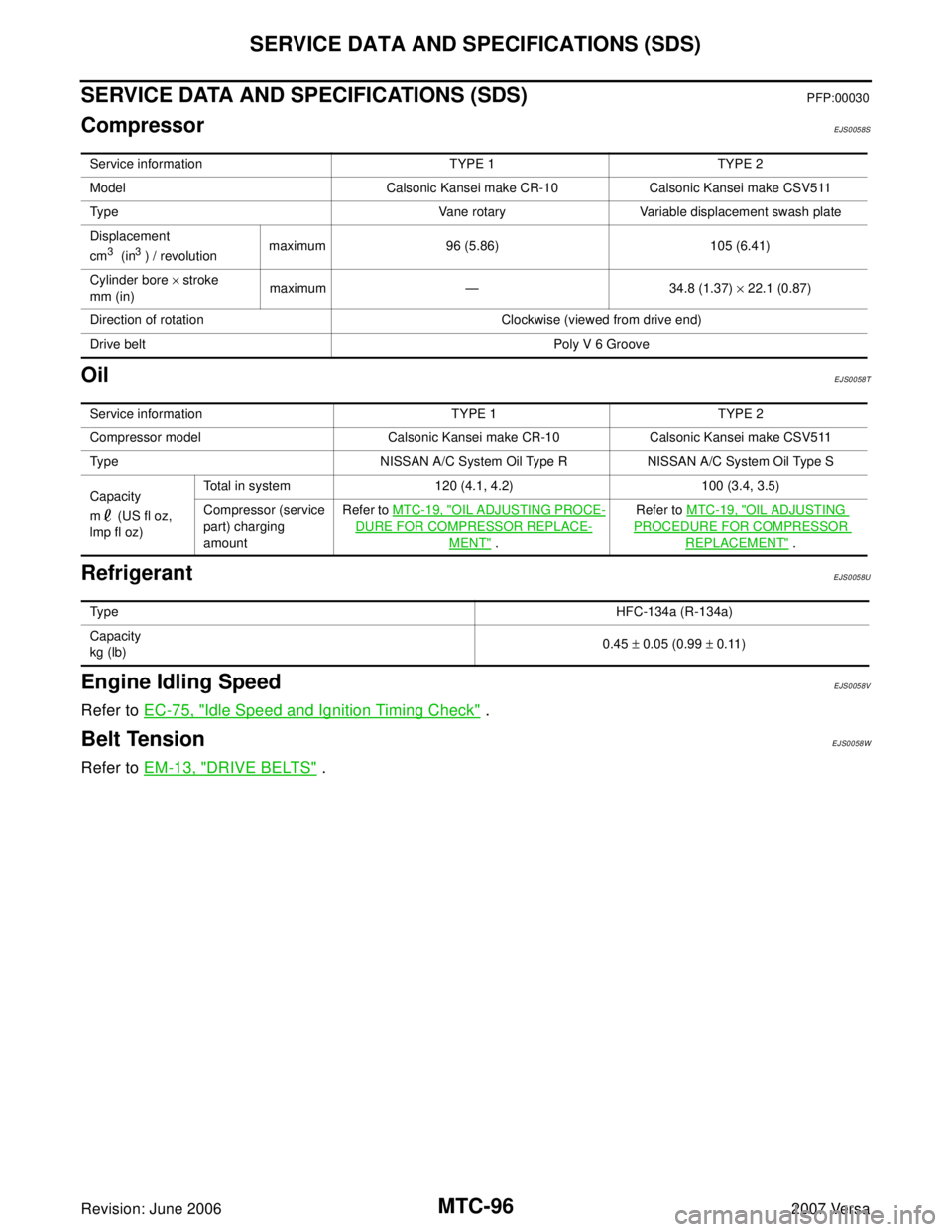
CompressorEJS0058S
OilEJS0058T
RefrigerantEJS0058U
Engine Idling SpeedEJS0058V
Refer to EC-75, "Idle Speed and Ignition Timing Check" .
Belt TensionEJS0058W
Refer to EM-13, "DRIVE BELTS" .
Service information TYPE 1 TYPE 2
Model Calsonic Kansei make CR-10 Calsonic Kansei make CSV511
Type Vane rotary Variable displacement swash plate
Displacement
cm
3 (in3 ) / revolutionmaximum 96 (5.86) 105 (6.41)
Cylinder bore × stroke
mm (in)maximum — 34.8 (1.37) × 22.1 (0.87)
Direction of rotation Clockwise (viewed from drive end)
Drive belt Poly V 6 Groove
Service information TYPE 1 TYPE 2
Compressor model Calsonic Kansei make CR-10 Calsonic Kansei make CSV511
Type NISSAN A/C System Oil Type R NISSAN A/C System Oil Type S
Capacity
m (US fl oz,
lmp fl oz)Total in system 120 (4.1, 4.2) 100 (3.4, 3.5)
Compressor (service
part) charging
amountRefer to MTC-19, "
OIL ADJUSTING PROCE-
DURE FOR COMPRESSOR REPLACE-
MENT" .Refer to MTC-19, "
OIL ADJUSTING
PROCEDURE FOR COMPRESSOR
REPLACEMENT" .
Ty p eHFC-134a (R-134a)
Capacity
kg (lb)0.45 ± 0.05 (0.99 ± 0.11)